


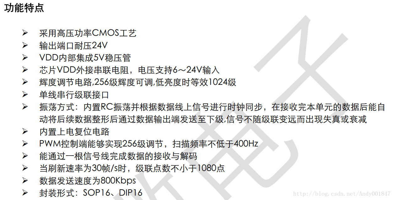
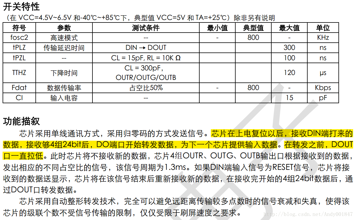
TM1812芯片的特性如下:
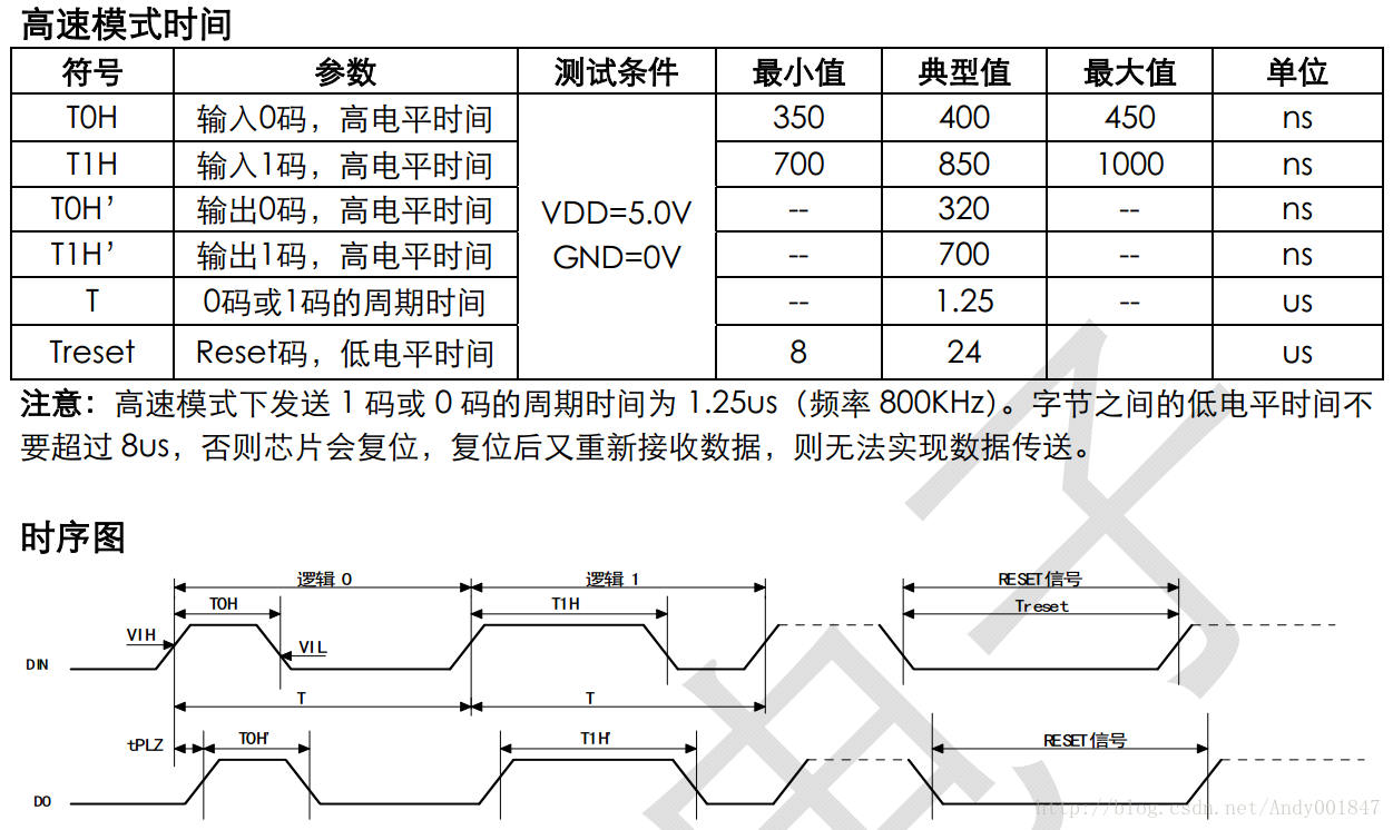
数据传输参数及时序:
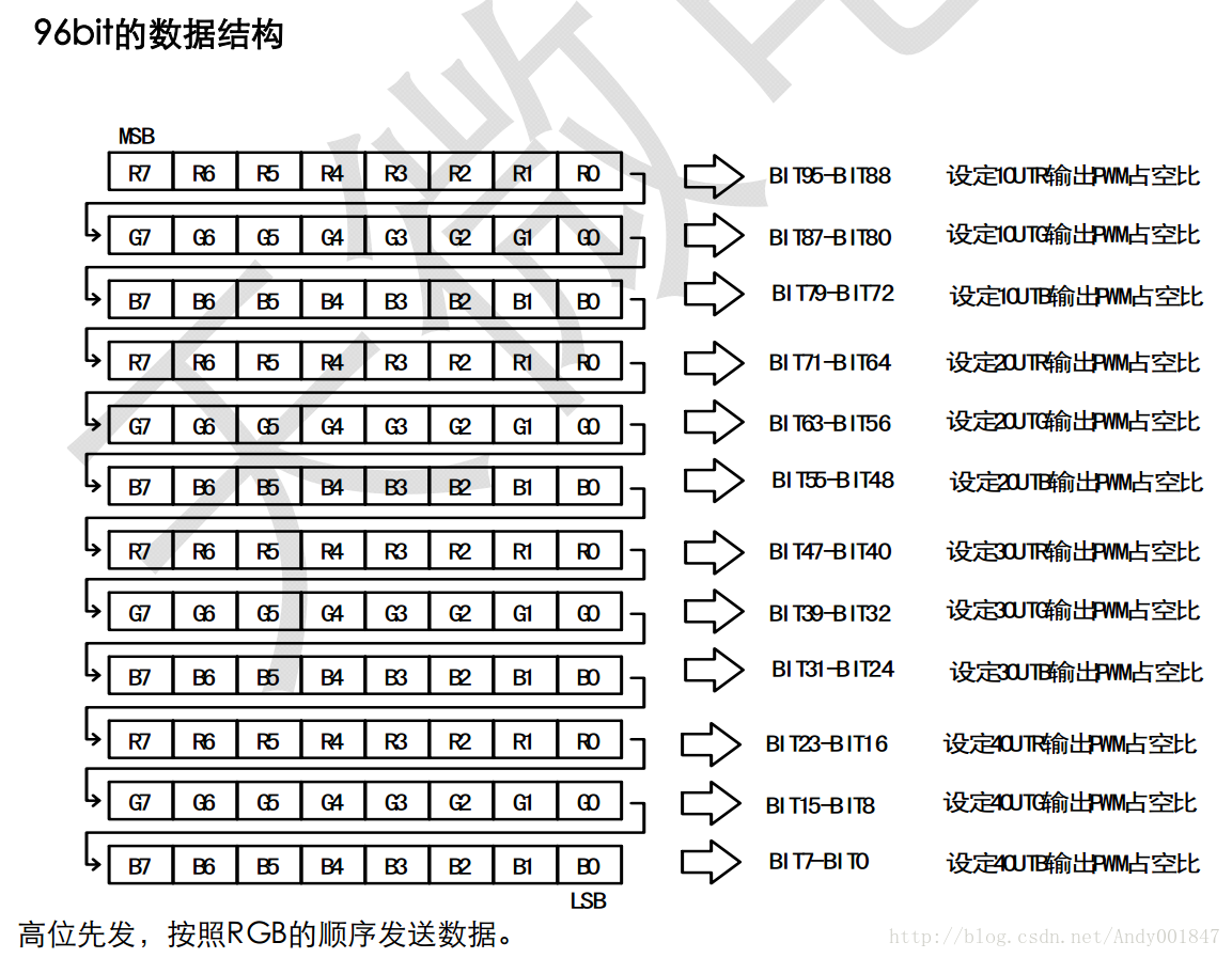
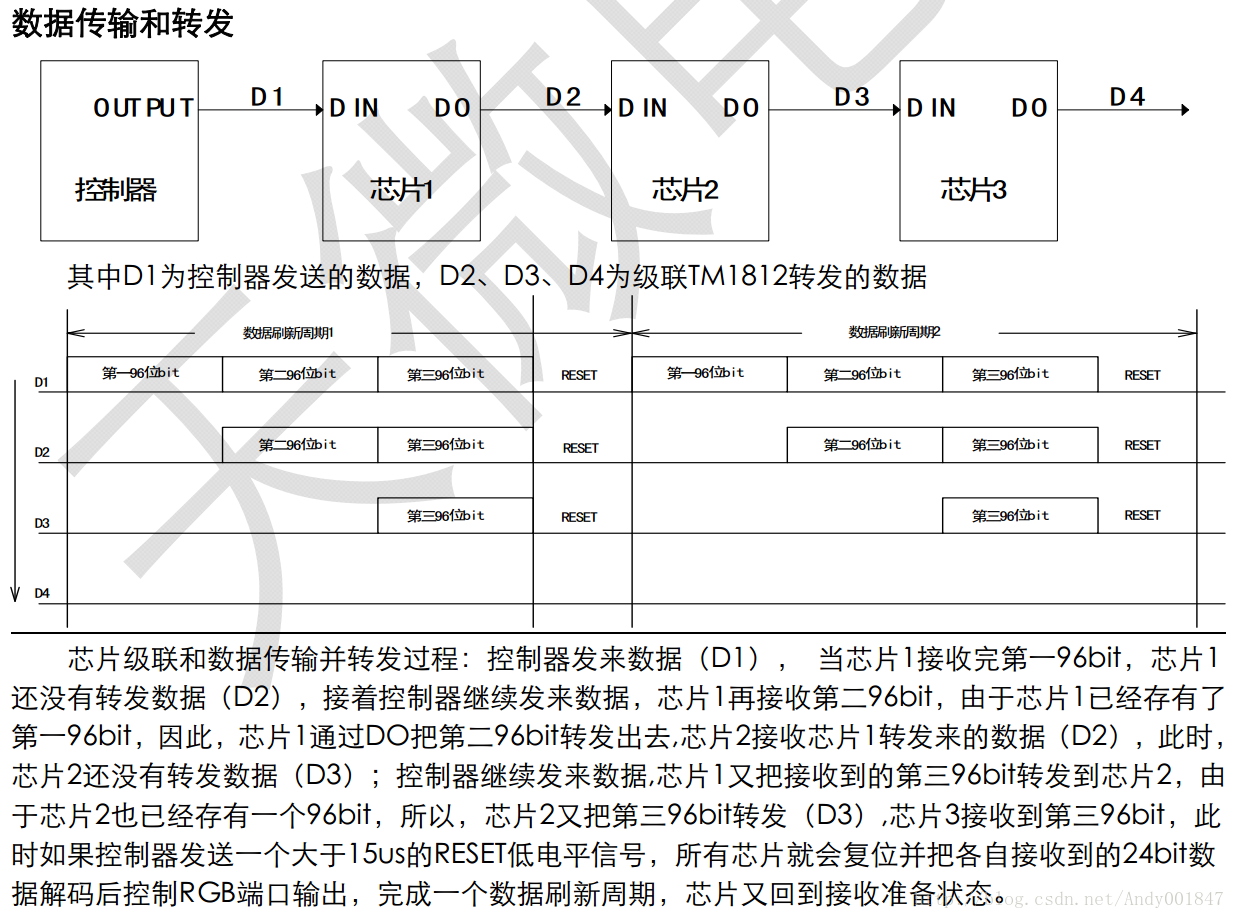
在上图中一个串联了三个TM1812芯片,每个芯片控制四盏灯,每盏灯有R,G,B三种颜色,每种颜色有256(0xFF)阶灰度可调,及每个颜色用一个字节控制。发送完全部LED灯的数据后,发送RESET信号进行LED显示以及重新接收数据。
下面是我在STM32F030C8T6中的驱动,时钟频率48MHz。
tm1812.h的代码:
#ifndef __LED_TM1812_H__
#define __LED_TM1812_H__  /* Define macro __LED_TM1812_H__ */

#ifdef __cplusplus
extern "C"{
#endif

#include <stdint.h>

#define    TM1812_CHIP_NUMBER     (8)    /* TM1812 chip number */
#define    ONE_RESOLUTION_SIZE    (TM1812_CHIP_NUMBER*4*3)  /* A row RGB LED bytes size, a TM1812 chip control 4 LEDs, a LED contain 3 bytes(R,G,B)*/

/* Data input channel */
typedef enum
{
    DIN1,
    DIN2,
    DIN3,
    DIN4,
}DIN_t;

/* Unipolar Return-to-zero code default low level, code 1, 1.25us */
#define  DIN_BIT_1(GPIO_Type, GPIO_Pin)    do                                      \
                                           {                                       \
                                               GPIO_Type->BSRR = GPIO_Pin;         \
                                               __NOP();__NOP();__NOP();__NOP();    \
                                               __NOP();__NOP();__NOP();__NOP();    \
                                               __NOP();__NOP();__NOP();__NOP();    \
                                               __NOP();__NOP();__NOP();__NOP();    \
                                               __NOP();__NOP();__NOP();__NOP();    \
                                               __NOP();__NOP();__NOP();__NOP();    \
                                               __NOP();__NOP();__NOP();__NOP();    \
                                               __NOP();__NOP();__NOP();__NOP();    \
                                               __NOP();__NOP();__NOP();__NOP();    \
                                               __NOP();__NOP();                    \
                                               GPIO_Type->BRR = GPIO_Pin;          \
                                               __NOP();__NOP();__NOP();            \
                                           }while(0)

/* Unipolar Return-to-zero code default low level, code 0, 1.25us */
#define  DIN_BIT_0(GPIO_Type, GPIO_Pin)    do                                      \
                                           {                                       \
                                               GPIO_Type->BSRR = GPIO_Pin;         \
                                               __NOP();__NOP();__NOP();__NOP();    \
                                               __NOP();__NOP();__NOP();__NOP();    \
                                               __NOP();__NOP();__NOP();__NOP();    \
                                               __NOP();__NOP();                    \
                                               GPIO_Type->BRR = GPIO_Pin;          \
                                               __NOP();__NOP();__NOP();__NOP();    \
                                               __NOP();__NOP();__NOP();__NOP();    \
                                               __NOP();__NOP();__NOP();__NOP();    \
                                               __NOP();__NOP();__NOP();__NOP();    \
                                               __NOP();__NOP();__NOP();__NOP();    \
                                               __NOP();__NOP();__NOP();__NOP();    \
                                               __NOP();__NOP();__NOP();__NOP();    \
                                               __NOP();                            \
                                           }while(0)

void TM1812_LEDInit(void);
void TM1812_DataPowerOn(void);
void TM1812_DataPoweOff(void);
int TM1812_WriteOneByte(DIN_t Din, uint8_t Data);
int TM1812_Reset(DIN_t Din);
int TM1812_TransmitData(DIN_t Din, const uint8_t* Data, uint32_t Size);
void TM1812_Test(void);

#ifdef __cplusplus
}
#endif

#endif /* End define macro __LED_TM1812_H__ */
tm1812.c代码:
#include "stm32f0xx_hal.h"
#include "led_tm1812.h"
#include "usart.h"
#include <string.h>
#include "cmsis_os.h"
#include <stdbool.h>

/*
** @Brief: execute nCount no operation, delay a short time
** @Parameters: us, delay us
** @Return: None
**/
static void DelayUs(uint32_t nUs)
{
    uint32_t Index = 0;
    uint32_t TmpIndex = 0;

    for(Index = 0; Index < nUs; Index++)
    {
        for(TmpIndex = 0; TmpIndex < 7; TmpIndex++)
        {
            __NOP();
        }
    }
}

/*
** @Brief: Init RGBLED tm1812 relative pins
** @Parameters: None
** @Return: None
**/
void TM1812_LEDInit(void)
{
    /*
     * DIN1   ---> PB4 (Output)
     * DIN2   ---> PB5 (Output)
     * DIN3   ---> PB10 (Output)
     * DIN4   ---> PB2 (Output)

     * LED_EN1 ---> PB6 (Output)
     */
    GPIO_InitTypeDef GPIO_InitStruct;

    /* GPIO Clock Enable */
    __HAL_RCC_GPIOB_CLK_ENABLE();

    /*Configure GPIO pins : PB2 PB10 PB4 PB5 */
    GPIO_InitStruct.Pin = GPIO_PIN_2 | GPIO_PIN_10 | GPIO_PIN_4 | GPIO_PIN_5;
    GPIO_InitStruct.Mode = GPIO_MODE_OUTPUT_PP;
    GPIO_InitStruct.Pull = GPIO_PULLDOWN;
    GPIO_InitStruct.Speed = GPIO_SPEED_FREQ_HIGH;
    HAL_GPIO_Init(GPIOB, &GPIO_InitStruct);

    /*Configure GPIO pins : PB6 */
    GPIO_InitStruct.Pin = GPIO_PIN_6;
    GPIO_InitStruct.Mode = GPIO_MODE_OUTPUT_PP;
    GPIO_InitStruct.Pull = GPIO_NOPULL;
    GPIO_InitStruct.Speed = GPIO_SPEED_FREQ_LOW;
    HAL_GPIO_Init(GPIOB, &GPIO_InitStruct);

    /* Configure GPIO pin default Output Level */
    /* DIN1, DIN2, DIN3, DIN4 default is low level */
    HAL_GPIO_WritePin(GPIOB, GPIO_PIN_2 | GPIO_PIN_4 | GPIO_PIN_5 | GPIO_PIN_10, GPIO_PIN_RESET);

    /* Power off TM1812 */
    HAL_GPIO_WritePin(GPIOB, GPIO_PIN_6, GPIO_PIN_RESET);
}

/*
** @Brief: Enable data input
** @Parameter: None
** @Return: None
**/
void TM1812_PowerOn(void)
{
    /*
     * LED_EN1 ---> PB6 (Output)
     */
    HAL_GPIO_WritePin(GPIOB, GPIO_PIN_6, GPIO_PIN_SET);
}

/*
** @Brief: Disable data input
** @Parameter: None
** @Return: None
**/
void TM1812_PowerOff(void)
{
    /*
     * LED_EN1 ---> PB6 (Output)
     */
    HAL_GPIO_WritePin(GPIOB, GPIO_PIN_6, GPIO_PIN_RESET);
}

/*
** @Brief: Data transmit is used unipolar return to zero code
** @Parameter: 1) Din, select data input port
               2) Data, one byte data that would be transmitted
** @Return: 1) 0, transmit successful
            2) -1, data input port error
**/
int TM1812_WriteOneByte(DIN_t Din, uint8_t Data)
{
    int BitIndex = 0;

    switch(Din)
    {
     case DIN1:
        for(BitIndex = 8*sizeof(Data)-1; BitIndex >= 0; BitIndex--)
        {
            if(Data & (0x01 << BitIndex))
            {
                DIN_BIT_1(GPIOB, GPIO_PIN_4);
            }
            else
            {
                DIN_BIT_0(GPIOB, GPIO_PIN_4);
            }
        }

        break;

     case DIN2:
        for(BitIndex = 8*sizeof(Data)-1; BitIndex >= 0; BitIndex--)
        {
            if(Data & (0x01 << BitIndex))
            {
                DIN_BIT_1(GPIOB, GPIO_PIN_5);
            }
            else
            {
                DIN_BIT_0(GPIOB, GPIO_PIN_5);
            }
        }

        break;

     case DIN3:
        for(BitIndex = 8*sizeof(Data)-1; BitIndex >= 0; BitIndex--)
        {
            if(Data & (0x01 << BitIndex))
            {
                DIN_BIT_1(GPIOB, GPIO_PIN_10);
            }
            else
            {
                DIN_BIT_0(GPIOB, GPIO_PIN_10);
            }
        }

        break;

     case DIN4:
        for(BitIndex = 8*sizeof(Data)-1; BitIndex >= 0; BitIndex--)
        {
            if(Data & (0x01 << BitIndex))
            {
                DIN_BIT_1(GPIOB, GPIO_PIN_2);
            }
            else
            {
                DIN_BIT_0(GPIOB, GPIO_PIN_2);
            }
        }

        break;

     default:
        return -1;
    }

    return 0;
}

/*
** @Brief: Send a reset signal
** @Parameter: Din, select data input port
** @Return: 1) 0, send a reset signal successful
            2) -1, data input port error
**/
int TM1812_Reset(DIN_t Din)
{
    switch(Din)
    {
     case DIN1:
         HAL_GPIO_WritePin(GPIOB, GPIO_PIN_4, GPIO_PIN_RESET);
         DelayUs(24);
         break;

     case DIN2:
         HAL_GPIO_WritePin(GPIOB, GPIO_PIN_5, GPIO_PIN_RESET);
         DelayUs(24);
         break;

     case DIN3:
         HAL_GPIO_WritePin(GPIOB, GPIO_PIN_10, GPIO_PIN_RESET);
         DelayUs(24);
         break;

     case DIN4:
         HAL_GPIO_WritePin(GPIOB, GPIO_PIN_2, GPIO_PIN_RESET);
         DelayUs(24);
         break;

     default:
         return -1;
    }

    return 0;
}

/*
** @Brief: Transmit LED data
** @Parameter: 1) Din, data input port
               2) Data, transmit data
               3) Size, data size
** @Return: 1) 0, transmit data successful
            2) -1, data is null or data size illegal
**/
int TM1812_TransmitData(DIN_t Din, const uint8_t* Data, uint32_t Size)
{
    int ByteIndex = 0;

    if((NULL == Data) || (Size != ONE_RESOLUTION_SIZE))
    {
        return -1;
    }

    /* Disable all maskable interrupts */
    taskDISABLE_INTERRUPTS();
    for(ByteIndex = 0; ByteIndex < Size; ByteIndex++)
    {
        TM1812_WriteOneByte(Din, Data[ByteIndex]);
    }
    /* Enable microcontroller interrupts */
    taskENABLE_INTERRUPTS();

    TM1812_Reset(Din);

    return 0;
}

/*
** Brief: Test Led only
**/
void TM1812_Test(void)
{
    uint8_t Data[ONE_RESOLUTION_SIZE] = {0};
    uint32_t DataSize = sizeof(Data) / sizeof(Data[0]);
    int DataIndex = 0;
    static int ColorFlag = 1;

    if(ColorFlag > 3)
    {
        ColorFlag = 1;
    }

    memset(Data, 0, DataSize);
    for(DataIndex = 0; DataIndex < DataSize; DataIndex++)
    {
        if(1 == ColorFlag)  /* Red */
        {
            if(((DataIndex+1) % 3) != 1)
            {
                Data[DataIndex] = 0x00;
            }
            else
            {
                Data[DataIndex] = 0xFF;
            }
        }
        else if(2 == ColorFlag)  /* Green */
        {
            if(((DataIndex+1) % 3) != 2)
            {
                Data[DataIndex] = 0x00;
            }
            else
            {
                Data[DataIndex] = 0xFF;
            }
        }
        else if(3 == ColorFlag)   /* Blue */
        {
            if(((DataIndex+1) % 3) != 0)
            {
                Data[DataIndex] = 0x00;
            }
            else
            {
                Data[DataIndex] = 0xFF;
            }
        }

        TM1812_TransmitData(DIN1, Data, DataSize);
        TM1812_TransmitData(DIN2, Data, DataSize);
        TM1812_TransmitData(DIN3, Data, DataSize);
        TM1812_TransmitData(DIN4, Data, DataSize);
    }

    memset(Data, 0, DataSize);
    for(DataIndex = DataSize - 1; DataIndex >= 0; DataIndex--)
    {
        if(1 == ColorFlag)  /* Red */
        {
            if(((DataIndex+1) % 3) != 1)
            {
                Data[DataIndex] = 0x00;
            }
            else
            {
                Data[DataIndex] = 0xFF;
            }
        }
        else if(2 == ColorFlag)  /* Green */
        {
            if(((DataIndex+1) % 3) != 2)
            {
                Data[DataIndex] = 0x00;
            }
            else
            {
                Data[DataIndex] = 0xFF;
            }
        }
        else if(3 == ColorFlag)   /* Blue */
        {
            if(((DataIndex+1) % 3) != 0)
            {
                Data[DataIndex] = 0x00;
            }
            else
            {
                Data[DataIndex] = 0xFF;
            }
        }

        TM1812_TransmitData(DIN1, Data, DataSize);
        TM1812_TransmitData(DIN2, Data, DataSize);
        TM1812_TransmitData(DIN3, Data, DataSize);
        TM1812_TransmitData(DIN4, Data, DataSize);
    }

    ColorFlag++;
}
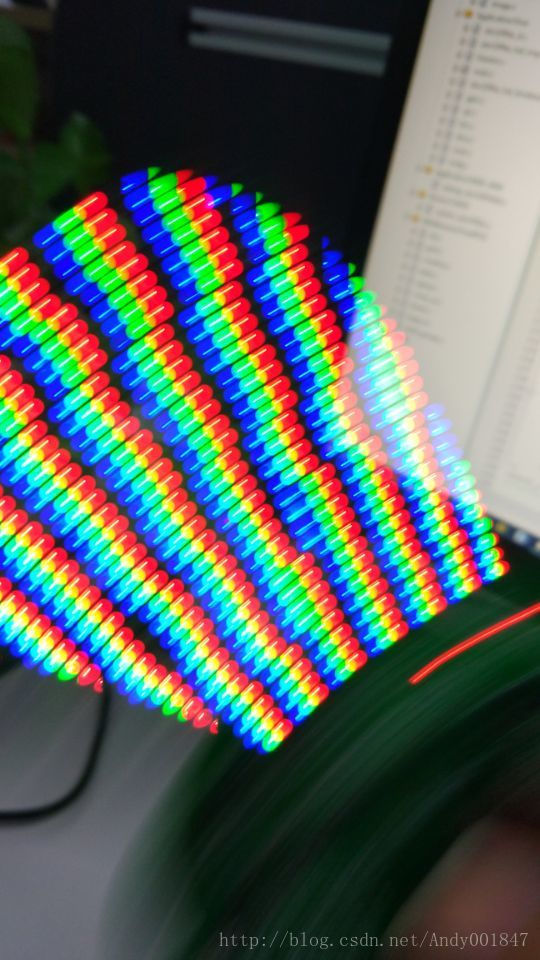
说明:该驱动程序连接了四排LED,每排串联了8个TM1812芯片,故分成了四个数据通道。
总结:TM1812适合做静态光源,不适合做动态显示,动态显示会出现不同芯片数据显示不同步(断层)现象。因为TM1812数据传输采取的是单极性归零码传输,是一种单线传输,芯片之间没有时钟线进行数据同步,数据线默认状态是低电平,而且在一定时间(大于8us)内没有传输数据就会自动复位,进入重新接收数据的状态,因此刷新频率较高并且在运动时,芯片之间数据不同步现象会非常明显。


 2339
2339


 被折叠的 条评论
为什么被折叠?
被折叠的 条评论
为什么被折叠?
 到【灌水乐园】发言


