


后面章节将分析 dma buffer 的管理,其中细节需要对音频数据相关概念有一定的了解。因此本章说明下音频数据中的几个重要概念:
- Sample:样本长度,音频数据最基本的单位,常见的有 8 位和 16 位;
- Channel:声道数,分为单声道 mono 和立体声 stereo;
- Frame:帧,构成一个完整的声音单元,Frame = Sample * channel;
- Rate:又称 sample rate,采样率,即每秒的采样次数,针对帧而言;
- Period size:周期,每次硬件中断处理音频数据的帧数,对于音频设备的数据读写,以此为单位;
- Buffer size:数据缓冲区大小,这里指 runtime 的 buffer size,而不是结构图 snd_pcm_hardware 中定义的 buffer_bytes_max;一般来说 buffer_size = period_size * period_count, period_count 相当于处理完一个 buffer 数据所需的硬件中断次数。
下面一张图直观的表示 buffer/period/frame/sample 之间的关系:
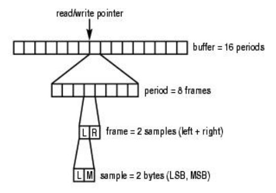
这个 buffer 中有 16 个 period,每当 DMA 搬运完一个 period 的数据就会出生一次中断,因此搬运这个 buffer中的数据将产生 16 次中断。ALSA 为什么这样做?因为数据缓存区可能很大,一次传输可能会导致不可接受的延迟;为了解决这个问题,所以将缓存区拆分成多个周期 period,以周期 period 为单元传输数据。
7.1. Frames & Periods
敏感的读者会察觉到 period 和 buffer size 在 PCM 数据搬运中扮演着非常重要角色。下面引用两段来自 alsa 官网对 Period 的详细解释:
Period
The interval between interrupts from the hardware. This defines the input latency, since the CPU will not have any idea that there is data waiting until the audio interface interrupts it.
The audio interface has a “pointer” that marks the current position for read/write in its h/w buffer. The pointer circles around the buffer as long as the interface is running.
Typically, there are an integral number of periods per traversal of the h/w buffer, but not always. There is at least one card (ymfpci) that generates interrupts at a fixed rate indepedent of the buffer size (which can be changed), resulting in some “odd” effects compared to more traditional designs.
Note: h/w generally defines the interrupt in frames, though not always.
Alsa’s period size setting will affect how much work the CPU does. if you set the period size low, there will be more interrupts and the work that is done every interrupt will be done more often. So, if you don’t care about low latency, set the period size large as possible and you’ll have more CPU cycles for other things. The defaults that ALSA provides are in the middle of the range, typically.
(from an old AlsaDevel thread[1], quoting Paul Davis)
Retrieved from “http://alsa.opensrc.org/Period”
FramesPeriods
A frame is equivalent of one sample being played, irrespective of the number of channels or the number of bits. e.g.
- 1 frame of a Stereo 48khz 16bit PCM stream is 4 bytes.
- 1 frame of a 5.1 48khz 16bit PCM stream is 12 bytes.
A period is the number of frames in between each hardware interrupt. The poll() will return once a period.
The buffer is a ring buffer. The buffer size always has to be greater than one period size. Commonly this is 2*period size, but some hardware can do 8 periods per buffer. It is also possible for the buffer size to not be an integer multiple of the period size.
Now, if the hardware has been set to 48000Hz , 2 periods, of 1024 frames each, making a buffer size of 2048 frames. The hardware will interrupt 2 times per buffer. ALSA will endeavor to keep the buffer as full as possible. Once the first period of samples has been played, the third period of samples is transfered into the space the first one occupied while the second period of samples is being played. (normal ring buffer behaviour).Additional example
Here is an alternative example for the above discussion.
Say we want to work with a stereo, 16-bit, 44.1 KHz stream, one-way (meaning, either in playback or in capture direction). Then we have:
- ‘stereo’ = number of channels: 2
- 1 analog sample is represented with 16 bits = 2 bytes
- 1 frame represents 1 analog sample from all channels; here we have 2 channels, and so: 1 frame = (num_channels) * (1 sample in bytes) = (2 channels) * (2 bytes (16 bits) per sample) = 4 bytes (32 bits)
- To sustain 2x 44.1 KHz analog rate - the system must be capable of data transfer rate, in Bytes/sec: Bps_rate = (num_channels) * (1 sample in bytes) * (analog_rate) = (1 frame) * (analog_rate) = ( 2 channels ) * (2 bytes/sample) * (44100 samples/sec) = 2*2*44100 = 176400 Bytes/secNow, if ALSA would interrupt each second, asking for bytes - we’d need to have 176400 bytes ready for it (at end of each second), in order to sustain analog 16-bit stereo @ 44.1Khz.
- If it would interrupt each half a second, correspondingly for the same stream we’d need 176400/2 = 88200 bytes ready, at each interrupt;
- if the interrupt hits each 100 ms, we’d need to have 176400*(0.1/1) = 17640 bytes ready, at each interrupt.We can control when this PCM interrupt is generated, by setting a period size, which is set in frames.
- Thus, if we set 16-bit stereo @ 44.1Khz, and the period_size to 4410 frames => (for 16-bit stereo @ 44.1Khz, 1 frame equals 4 bytes - so 4410 frames equal 4410*4 = 17640 bytes) => an interrupt will be generated each 17640 bytes - that is, each 100 ms.
- Correspondingly, buffer_size should be at least 2*period_size = 2*4410 = 8820 frames (or 8820*4 = 35280 bytes).It seems (writing-an-alsa-driver.pdf), however, that it is the ALSA runtime that decides on the actual buffer_size and period_size, depending on: the requested number of channels, and their respective properties (rate and sampling resolution) - as well as the parameters set in the snd_pcm_hardware structure (in the driver).
Also, the following quote may be relevant, from “(alsa-devel) Questions about writing a new ALSA driver for a very limitted device”:The “frame” represents the unit, 1 frame = # channels x sample_bytes.
In your case, 1 frame corresponds to 2 channels x 16 bits = 4 bytes.The periods is the number of periods in a ring-buffer. In OSS, called
as “fragments”.So,
- buffer_size = period_size * periods
- period_bytes = period_size * bytes_per_frame
- bytes_per_frame = channels * bytes_per_sampleI still don’t understand what ‘period_size’ and a ‘period’ is?
The “period” defines the frequency to update the status, usually via the invokation of interrupts. The “period_size” defines the frame sizes corresponding to the “period time”. This term corresponds to the “fragment size” on OSS. On major sound hardwares, a ring-buffer is divided to several parts and an irq is issued on each boundary. The period_size defines the size of this chunk.
On some hardwares, the irq is controlled on the basis of a timer. In this case, the period is defined as the timer frequency to invoke an irq.
这里不做翻译了,简单说下 Frame 和 Period 要点:
- Frame:帧,构成一个完整的声音单元,它的大小等于 sample_bits * channels;
- Peroid:周期大小,即每次 dma 硬件中断处理音频数据的帧数。如果周期大小设定得较大,则单次处理的数据较多,这意味着单位时间内硬件中断的次数较少,CPU 也就有更多时间处理其他任务,功耗也更低,但这样也带来一个显著的弊端——数据处理的时延会增大。
再说说 period bytes,对于 dma 处理来说,它关心的是数据大小,而不管 period size 和 period count,因此有个转换关系:
period_bytes = period_size * sample_bits * channels / 8
由于 I2S 总线采样率是稳定的,我们可以计算 I2S 传输一个周期的数据所需的时间:
transfer_time = 1 * period_size / sample_rate, in second
例如 period_size = 1024,sample_rate = 48KHz 时,那么传输时间为 1 * 1024 / 48000 = 21.3 (ms)。
7.2. hrtimer 模拟 PCM 周期中断
在 4.2.1. pcm operations 章节中,我们提到:每次 dma 传输完成一个周期的数据传输后,都要调用 snd_pcm_period_elapsed() 告知 pcm native 一个周期的数据已经传送到 FIFO 上了,然后再次调用 dma 传输音频数据…如此循环。
但有些 Platform 可能由于设计如此或设计缺陷,dma 传输完一个周期的数据不会产生硬件中断。这样系统如何知道什么时候传输完一个周期的数据了呢?在上个章节的最后,我们提到 I2S 总线传输一个周期的数据所需的时间,这其实也是 dma 搬运一个周期的数据所需的时间,这很容易理解:I2S FIFO 消耗完一个周期的数据,dma 才接着搬运一个周期的数据到 I2S FIFO。
因此我们可以用定时器来模拟这种硬件中断:
- 1). 触发dma搬运数据时,启动定时器开始计时;
- 2). 当定时到 1 * period_size / sample_rate,这时 I2S 已传输完一个周期的音频数据了,进入定时器中断处理:调用 snd_pcm_period_elapsed() 告知 pcm native 一个周期的数据已经处理完毕了,同时准备下一次的数据搬运;
- 3). 继续执行步骤 1)…
为了更好保证数据传输的实时性,建议采用高精度定时器 hrtimer。
作者见过至少两家芯片在传输音频数据时需要用定时器模拟周期中断,一是 MTK 的智能手机处理器,二是 Freescale 的 i.MX 系列处理器。后者已经合入 Linux 内核代码,具体见:sound/soc/imx/imx-pcm-fiq.c,这里简略分析:
// 定时器中断处理例程
static enum hrtimer_restart snd_hrtimer_callback(struct hrtimer *hrt)
{
    ...

    /* If we've transferred at least a period then report it and
     * reset our poll time */
    if (delta >= iprtd->period) {
        snd_pcm_period_elapsed(substream); // 告知 pcm native 一个周期的数据已经处理完毕
        iprtd->last_offset = iprtd->offset;
    }

    hrtimer_forward_now(hrt, ns_to_ktime(iprtd->poll_time_ns)); // 重新计时,poll_time_ns:I2S 传输一个周期的数据所需的时间
    return HRTIMER_RESTART;
}

// hw_params 回调,数据传输开始前,先设置 dma 传输参数
static int snd_imx_pcm_hw_params(struct snd_pcm_substream *substream,
                struct snd_pcm_hw_params *params)
{
    struct snd_pcm_runtime *runtime = substream->runtime;
    struct imx_pcm_runtime_data *iprtd = runtime->private_data;

    iprtd->size = params_buffer_bytes(params);    // dma 缓冲区大小
    iprtd->periods = params_periods(params);      // 周期数
    iprtd->period = params_period_bytes(params) ; // 周期大小
    iprtd->offset = 0;
    iprtd->last_offset = 0;
    iprtd->poll_time_ns = 1000000000 / params_rate(params) *
                params_period_size(params);       // 计算 I2S 传输一个周期的数据所需的时间
    snd_pcm_set_runtime_buffer(substream, &substream->dma_buffer); // 设置 dma 缓冲区

    return 0;
}

// trigger 回调,触发 dma 传输或停止
static int snd_imx_pcm_trigger(struct snd_pcm_substream *substream, int cmd)
{
    struct snd_pcm_runtime *runtime = substream->runtime;
    struct imx_pcm_runtime_data *iprtd = runtime->private_data;

    switch (cmd) {
    case SNDRV_PCM_TRIGGER_START:
    case SNDRV_PCM_TRIGGER_RESUME:
    case SNDRV_PCM_TRIGGER_PAUSE_RELEASE:
        atomic_set(&iprtd->running, 1);
        hrtimer_start(&iprtd->hrt, ns_to_ktime(iprtd->poll_time_ns), // 准备传输数据,启动定时器,开始计时
              HRTIMER_MODE_REL);
        if (++fiq_enable == 1)
            enable_fiq(imx_pcm_fiq); // 开始 dma 传输

        break;

    case SNDRV_PCM_TRIGGER_STOP:
    case SNDRV_PCM_TRIGGER_SUSPEND:
    case SNDRV_PCM_TRIGGER_PAUSE_PUSH:
        atomic_set(&iprtd->running, 0);

        if (--fiq_enable == 0)
            disable_fiq(imx_pcm_fiq); // 停止 dma 传输

        break;
    default:
        return -EINVAL;
    }

    return 0;
}


 1704
1704


 被折叠的 条评论
为什么被折叠?
被折叠的 条评论
为什么被折叠?
 到【灌水乐园】发言


