


TB6612FNG 电机驱动模块
该模块相对于传统的L298N效率上提高很多,体积上也大幅度减少,在额定范围内,芯片基本不发热。
TB6612FNG每通道输出最高1.2 A的连续驱动电流,启动峰值电流达2A/3.2 A(连续脉冲/单脉冲);
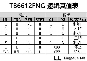
4种电机控制模式:正转/反转/制动/停止;
PWM支持频率高达100 kHz;
待机状态;
片内低压检测电路与热停机保护电路;
工作温度:-20~85℃;
SSOP24小型贴片封装。
本篇文章参考任意门
http://bildr.org/2012/04/tb6612fng-arduino/
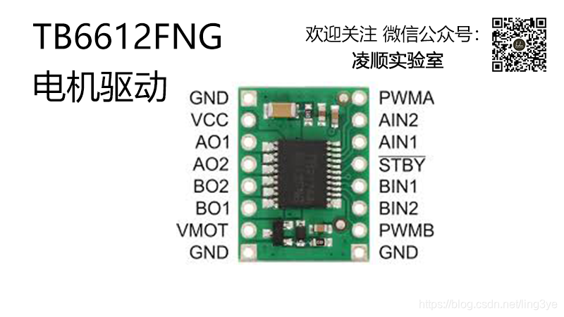
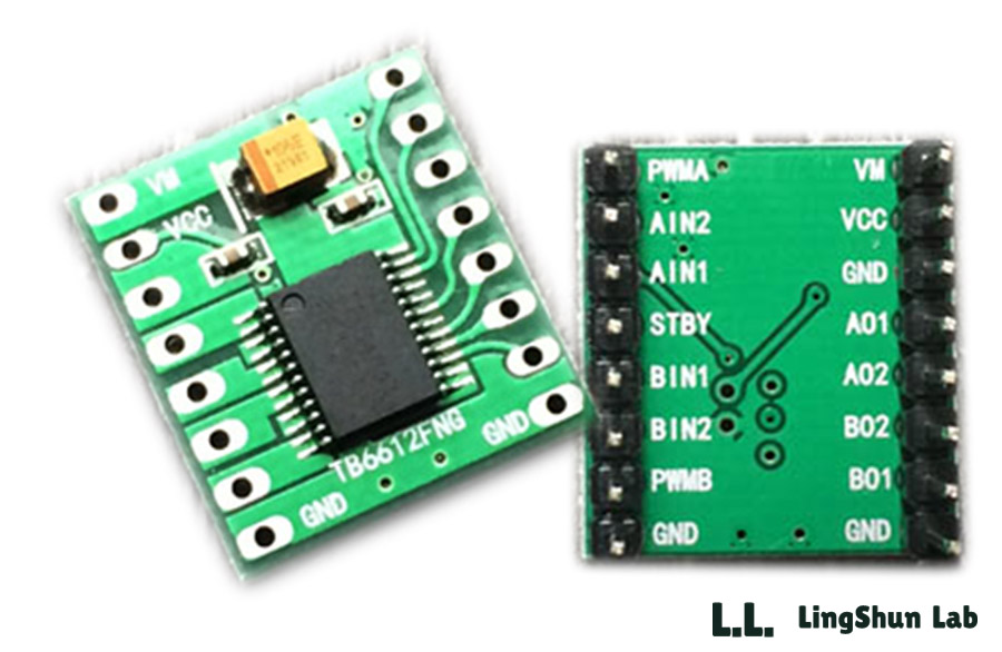
引脚说明
A控制信号输入------PWMA VM ------电机驱动电压输入端(4.5V-15V)
A电机输入端2 ------AIN2 VCC ------逻辑电平输入端(2.7V-5.5V)
A电机输入端1 ------AIN1 GND ------ 接地
正常工作/待机状态控制端------STBY AO1 ------- A电机输出端1
B电机输入端1------BIN1 AO2 ------ A电机输出端2
B电机输入端2------BIN2 BO2 ------ B电机输出端2
B控制信号输入端------PWMB BO1 ------ B电机输出端1
接地------GND GND ------- 接地
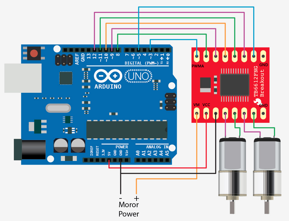
接线方式
程序实现
程序打包下载:https://u16460183.ctfile.com/fs/16460183-295784301
//motor A connected between A01 and A02
//motor B connected between B01 and B02

int STBY = 10; //standby

//Motor A
int PWMA = 3; //Speed control
int AIN1 = 9; //Direction
int AIN2 = 8; //Direction

//Motor B
int PWMB = 5; //Speed control
int BIN1 = 11; //Direction
int BIN2 = 12; //Direction

void setup(){
  pinMode(STBY, OUTPUT);

  pinMode(PWMA, OUTPUT);
  pinMode(AIN1, OUTPUT);
  pinMode(AIN2, OUTPUT);

  pinMode(PWMB, OUTPUT);
  pinMode(BIN1, OUTPUT);
  pinMode(BIN2, OUTPUT);
}

void loop(){
  move(1, 255, 1); //motor 1, full speed, left
  move(2, 255, 1); //motor 2, full speed, left

  delay(1000); //go for 1 second
  stop(); //stop
  delay(250); //hold for 250ms until move again

  move(1, 128, 0); //motor 1, half speed, right
  move(2, 128, 0); //motor 2, half speed, right

  delay(1000);
  stop();
  delay(250);
}


void move(int motor, int speed, int direction){
//Move specific motor at speed and direction
//motor: 0 for B 1 for A
//speed: 0 is off, and 255 is full speed
//direction: 0 clockwise, 1 counter-clockwise

  digitalWrite(STBY, HIGH); //disable standby

  boolean inPin1 = LOW;
  boolean inPin2 = HIGH;

  if(direction == 1){
    inPin1 = HIGH;
    inPin2 = LOW;
  }

  if(motor == 1){
    digitalWrite(AIN1, inPin1);
    digitalWrite(AIN2, inPin2);
    analogWrite(PWMA, speed);
  }else{
    digitalWrite(BIN1, inPin1);
    digitalWrite(BIN2, inPin2);
    analogWrite(PWMB, speed);
  }
}

void stop(){
//enable standby
  digitalWrite(STBY, LOW);
}
实例效果
通电,并测量马达A与B的输出电压,基本相同,电压差在正负0.03V,输出稳定。
想必能完美解决L9110S 和 L298N两路电机输出电压误差大导致的走不到直线。


 1万+
1万+


 被折叠的 条评论
为什么被折叠?
被折叠的 条评论
为什么被折叠?
 到【灌水乐园】发言


