


一、 测试DS3231芯片RTC可以正常工作
终端输入date010203042011 表示时间为:2011 01 0203:04
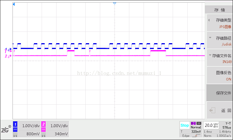
二、 在示波器上显示如下波形,示波器抓取波形

蓝色为SCL信号
红色为SDA信号
1.第一个周期起始位置时,SCL保持高电平,SDA发生负跳变是start标志。
第一个周期解析SDA信号:11010000 ,高7位表示设备号(slave address),第8位表示R/W-,1代表读,0代表写,这里为写入数据。
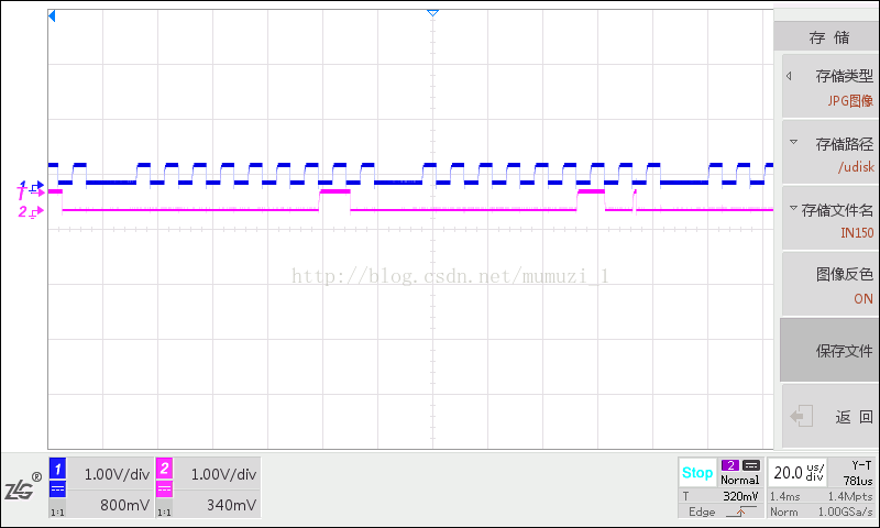
2.第二个周期为flags,在i2c-core.c中解释如下
@flags: I2C_M_RD is handled by all adapters. No other flags may be
* provided unless the adapter exported therelevant I2C_FUNC_*
* flags through i2c_check_functionality().
* Alternatively,supports I2C_FUNC_PROTOCOL_MANGLINGthen
* passingcertain @flags may have changed thosestandard protocol behaviors.
* Those flagsare only for use with broken/nonconforming slaves, and with
* adapterswhich are known to support the specific mangling options they
* need (one ormore of IGNORE_NAK, NO_RD_ACK, NOSTART, and REV_DIR_ADDR).
当支持I2C_FUNC_PROTOCOL_MANGLING时flags才会改变,这里不支持I2C_FUNC_PROTOCOL_MANGLING,所以flages为00000000。在第二个周期结束前会有一个ack应答,标志着将要发送下一个周期的数据。
.

3.第三个周期为message length,发送的数据长度。11010001=0xd1,数据长度指的是buf中的数据长度,不包括slave addr和msg_len。
4.第四个周期开始发送数据。
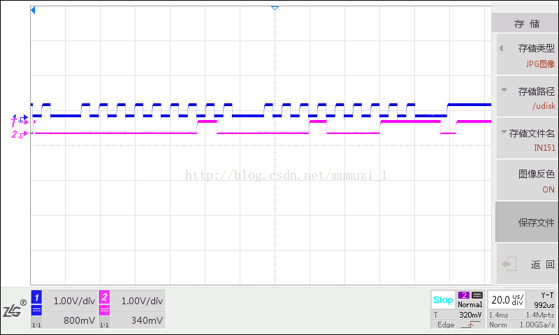

5.第10周期结束时,第9位SCL高电平是SDA对应位低电平,产生了一个NACK,且第11周期SCL保持高电平,SDA发生正跳变,产生了stop位,标志着i2c_msg数据的第一个周期发送完毕。
6.分析从第4周期是产生的SDA信号,如下。
00000110 0 00000100 0 00000011 0 00000001 0 00000010 000000001 0 00010001 1
从内核rtc-ds1307.c中可以查到时间数据写入的顺序如下:
static int ds1307_set_time(struct device *dev, struct rtc_time *t)
{
struct ds1307 *ds1307 = dev_get_drvdata(dev);
int result;
int tmp;
u8 *buf= ds1307->regs;
dev_dbg(dev,"%s secs=%d, mins=%d, "
"hours=%d,mday=%d, mon=%d, year=%d, wday=%d\n",
"write",t->tm_sec, t->tm_min,
t->tm_hour,t->tm_mday,
t->tm_mon,t->tm_year, t->tm_wday);
buf[DS1307_REG_SECS]= bin2bcd(t->tm_sec);
buf[DS1307_REG_MIN]= bin2bcd(t->tm_min);
buf[DS1307_REG_HOUR]= bin2bcd(t->tm_hour);
buf[DS1307_REG_WDAY]= bin2bcd(t->tm_wday + 1);
buf[DS1307_REG_MDAY]= bin2bcd(t->tm_mday);
buf[DS1307_REG_MONTH]= bin2bcd(t->tm_mon + 1);
/* assume20YY not 19YY */
tmp = t->tm_year - 100;
buf[DS1307_REG_YEAR]= bin2bcd(tmp);
………………
………………
}
顺序位:sec min hour day day mon year
对应第4-10周期的数据如下:
00000110 0 00000100 0 00000011 0 00000001 0 00000010 000000001 0 00010001 1
6秒 4分 3时 星期一 2日 1月 11年
可以看到写入时钟的时间和示波器抓取信号解析出来的时间数据是一致的。
三、分析数据如何通过i2c进行传输的
1.rtc-ds1307.c中找到时间的写入函数:
static int ds1307_set_time(struct device *dev,struct rtc_time *t)
{
………………
result = ds1307->write_block_data(ds1307->client,ds1307->offset,7, buf);
………………
}
2.跟踪ds1307->write_block_data,在函数:ds1307_probe中调用
static int __devinit ds1307_probe(struct i2c_client *client,const struct i2c_device_id *id)
{
if(i2c_check_functionality(adapter, I2C_FUNC_SMBUS_I2C_BLOCK)) {
ds1307->read_block_data= i2c_smbus_read_i2c_block_data;
ds1307->write_block_data= i2c_smbus_write_i2c_block_data;
} else {
ds1307->read_block_data= ds1307_read_block_data;
ds1307->write_block_data= ds1307_write_block_data;
}
}
因为rtc是挂载在i2c上的,这里通过模拟smbus总线进行数据读写,所以进入
ds1307->write_block_data = i2c_smbus_write_i2c_block_data;
3.跟踪函数:i2c_smbus_write_i2c_block_data,在i2c-core.c中实现
s32 i2c_smbus_write_i2c_block_data(const struct i2c_client*client, u8 command,u8 length, const u8 *values)
{
//i2c_smbus_xfer执行SMBus协议操作
return i2c_smbus_xfer(client->adapter,client->addr, client->flags,
I2C_SMBUS_WRITE,command,
I2C_SMBUS_I2C_BLOCK_DATA,&data);
}
到这里,可以看到时间的数据是通过i2c_smbus_xfer写入的,跟踪这个函数的具体实现
4.跳转到函数i2c_smbus_xfer,这里有smbus_xfer和i2c_smbus_xfer_emulated两种方式实现数据写入,因为i2c主控制器一般不支持smbus_xfer,所以选择i2c_smbus_xfer_emulated来实现。,进入函数:
s32 i2c_smbus_xfer(struct i2c_adapter *adapter, u16 addr,unsigned short flags,char read_write, u8 command, int protocol,unioni2c_smbus_data *data)
{
/* i2c主控制器一般不支持smbus_xfer*/
res =adapter->algo->smbus_xfer(adapter,addr, flags,read_write, command,
protocol, data);
res = i2c_smbus_xfer_emulated(adapter, addr, flags,read_write,
command, protocol,data);
}
5.跟踪i2c_smbus_xfer_emulated函数,进入switch语句中,这里主要就是针对i2c_smbus一系列函数,根据传入的size,调用不同的函数来读写数据,在rtc-ds1307.c中调用了i2c_smbus_write_i2c_block_data函数,size大小为函数: i2c_smbus_xfer(client->adapter,client->addr, client->flags,I2C_SMBUS_WRITE, command,I2C_SMBUS_I2C_BLOCK_DATA,&data); 中的I2C_SMBUS_I2C_BLOCK_DATA,进入case语句:caseI2C_SMBUS_I2C_BLOCK_DATA: ,
static s32 i2c_smbus_xfer_emulated(structi2c_adapter *adapter, u16 addr,
unsigned short flags,
char read_write, u8 command, int size,
union i2c_smbus_data *data)
{
switch (size) {
caseI2C_SMBUS_QUICK:
msg[0].len = 0;
/* Special case: The read/write field isused as data */
msg[0].flags = flags | (read_write ==I2C_SMBUS_READ ?
I2C_M_RD : 0);
num = 1;
break;
case I2C_SMBUS_BYTE:
if (read_write == I2C_SMBUS_READ) {
/* Special case: only a read! */
msg[0].flags = I2C_M_RD | flags;
num= 1;
}
break;
case I2C_SMBUS_BYTE_DATA:
if (read_write == I2C_SMBUS_READ)
msg[1].len = 1;
else {
msg[0].len = 2;
msgbuf0[1] = data->byte;
}
break;
case I2C_SMBUS_WORD_DATA:
if (read_write == I2C_SMBUS_READ)
msg[1].len = 2;
else {
msg[0].len = 3;
msgbuf0[1] = data->word &0xff;
msgbuf0[2] = data->word >>8;
}
break;
case I2C_SMBUS_PROC_CALL:
num = 2; /* Special case */
read_write = I2C_SMBUS_READ;
msg[0].len = 3;
msg[1].len = 2;
msgbuf0[1] = data->word & 0xff;
msgbuf0[2] = data->word >> 8;
break;
case I2C_SMBUS_BLOCK_DATA:
if (read_write == I2C_SMBUS_READ) {
msg[1].flags |= I2C_M_RECV_LEN;
msg[1].len = 1; /* block length willbe added by
the underlying bus driver */
} else {
msg[0].len = data->block[0] + 2;
if (msg[0].len >I2C_SMBUS_BLOCK_MAX + 2) {
dev_err(&adapter->dev,
"Invalid block writesize %d\n",
data->block[0]);
return -EINVAL;
}
for (i = 1; i < msg[0].len; i++)
msgbuf0[i] = data->block[i-1];
}
break;
case I2C_SMBUS_BLOCK_PROC_CALL:
num = 2; /* Another special case */
read_write = I2C_SMBUS_READ;
if (data->block[0] >I2C_SMBUS_BLOCK_MAX) {
dev_err(&adapter->dev,
"Invalid block write size%d\n",
data->block[0]);
return -EINVAL;
}
msg[0].len = data->block[0] + 2;
for (i = 1; i < msg[0].len; i++)
msgbuf0[i] = data->block[i-1];
msg[1].flags |= I2C_M_RECV_LEN;
msg[1].len = 1; /* block length will beadded by
the underlying bus driver */
break;
case I2C_SMBUS_I2C_BLOCK_DATA:
if (read_write == I2C_SMBUS_READ) {
msg[1].len = data->block[0];
} else {
msg[0].len = data->block[0] + 1;
if (msg[0].len >I2C_SMBUS_BLOCK_MAX + 1) {
dev_err(&adapter->dev,
"Invalid block writesize %d\n",
data->block[0]);
return -EINVAL;
}
for (i = 1; i <=data->block[0]; i++)
msgbuf0[i] = data->block[i];
}
break;
default:
dev_err(&adapter->dev,"Unsupported transaction %d\n", size);
return -EOPNOTSUPP;
}
}
status = i2c_transfer(adapter, msg, num);
if (status < 0)
return status;
}
6. 将数据写入以i2c_msg后调用函数:i2c_transfer(adapter, msg, num);这个函数才是真正传输i2c_msg数据的函数。
继续跟踪函数i2c_transfer(),最终调用了底层的adap->algo->master_xfer(adap, msgs,num)函数,在i2c.h中定义了一个结构体:
struct i2c_algorithm {
int (*master_xfer)(struct i2c_adapter *adap, struct i2c_msg*msgs,int num);
int (*smbus_xfer) (struct i2c_adapter *adap, u16 addr,unsigned short flags, char read_write, u8 command, int size, unioni2c_smbus_data *data);
u32 (*functionality)(struct i2c_adapter *);
};
i2c_algotithm实现的是i2c数据传输的算法,通过调用master_xfer,周期性的发送i2c_msg。到这里,可以将i2c_msg的数据全部发送出去,i2c_msg结构体中包含了slave addr,flags,msg_len,buf。
int i2c_transfer(struct i2c_adapter *adap, struct i2c_msg*msgs, int num)
{
ret = adap->algo->master_xfer(adap, msgs,num);
}
struct i2c_msg{
__u16 addr; /* slave address */
__u16 flags;
#define I2C_M_TEN 0x0010 /* this is a ten bit chipaddress */
#define I2C_M_RD 0x0001 /* read data, from slave tomaster */
#define I2C_M_NOSTART 0x4000 /* ifI2C_FUNC_PROTOCOL_MANGLING */
//表示把读写标志位反转,也就是读是把相应位置0
#define I2C_M_REV_DIR_ADDR 0x2000 /* ifI2C_FUNC_PROTOCOL_MANGLING */
//设置这个标志意味当前i2c_msg忽略I2C器件的ack和nack信号。
#define I2C_M_IGNORE_NAK 0x1000 /* ifI2C_FUNC_PROTOCOL_MANGLING */
//这个标识表示在正行读操作时不去ACK
#define I2C_M_NO_RD_ACK 0x0800 /* ifI2C_FUNC_PROTOCOL_MANGLING */
#define I2C_M_RECV_LEN 0x0400 /* length will be firstreceived byte */
__u16 len; /* msg length */
__u8 *buf; /* pointer to msg data */
};
总结一下,在i2c上进行数据传输,都是通过一个叫i2c_smbus_xfer的函数进行传输,这个函数被i2c_smbus函数族所调用,不同的i2c_smbus函数族的函数调用时都会传入一个i2c_smbus_xfer_emulated函数的switch中所需要的size,在case分支中将不同的数据写入i2c_msg结构体成员,然后执行i2c_smbus_xfer_emulated中的i2c_transfer,i2c_transfer最终调用了i2c_algorithm算法实现中的master_xfer周期性的发送i2c_msg结构体中的数据。
注:
i2c_smbus函数族是自己起的名字,包含以下函数:
/* Now follow the 'nice' access routines. These alsodocument the calling
conventionsof i2c_smbus_xfer. */
extern s32 i2c_smbus_read_byte(const struct i2c_client*client);
extern s32 i2c_smbus_write_byte(const struct i2c_client*client, u8 value);
extern s32 i2c_smbus_read_byte_data(const structi2c_client *client,
u8 command);
extern s32 i2c_smbus_write_byte_data(const structi2c_client *client,
u8 command, u8 value);
extern s32 i2c_smbus_read_word_data(const structi2c_client *client,
u8 command);
extern s32 i2c_smbus_write_word_data(const structi2c_client *client,
u8 command, u16 value);
/* Returns the number of read bytes */
extern s32 i2c_smbus_read_block_data(const structi2c_client *client,
u8 command, u8 *values);
extern s32 i2c_smbus_write_block_data(const structi2c_client *client,
u8 command, u8 length, const u8 *values);
/* Returns the number of read bytes */
extern s32 i2c_smbus_read_i2c_block_data(const structi2c_client *client,
u8 command, u8 length, u8 *values);
extern s32 i2c_smbus_write_i2c_block_data(const structi2c_client *client,
u8 command, u8 length,
const u8 *values);


 212
212


 被折叠的 条评论
为什么被折叠?
被折叠的 条评论
为什么被折叠?
 到【灌水乐园】发言


