win32两种填充模式ALTERNATE和WINDING的区别

刚学到windows程序设计的填充模式时,对于ALTERNATE和WINDING这两种模式还是
有点晕乎乎的,看了下msdn

When the fill mode is ALTERNATE, GDI fills the area between odd-numbered and even-numbered polygon sides on each scan line. That is, GDI fills the area between the first and second side, between the third and fourth side, and so on. 

When the fill mode is WINDING, GDI fills any region that has a nonzero winding value. This value is defined as the number of times a pen used to draw the polygon would go around the region. The direction of each edge of the polygon is important. 

这是msdn原话,翻译过来大概就是:
当填充模式为ALTERNATE时,GDI填充每条扫描线的从多边形的奇数边到偶数边的区域,也就是说,GDI填充第一条边到第二条边到区域,第三条到第四条边的区域,等等……..
当填充模式为WINDING时,GDI填充任何非零绕组值的区域,这个值被定义为笔的次数用来画多边形会在该地区。多边形的每条边的方向是很重要的(这里说的有点模糊)
我搜了搜,网上有很多判别的方法,
这里写图片描述
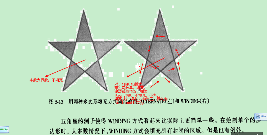
左边是ALTERNATE模式,这里介绍两种方法吧,
一:判断多边形某个区域是否填充,那么从该区域内一点向外做一射线,如果经过的边数为奇数,填充,偶数不填充,这个例子由于穿过两条,所以填充,
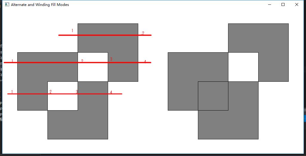
二:这是msdn说的方法,就是做一水平直线,依次记下穿过的边数,奇数到偶数之间的区域则填充(比如1到2),偶数到奇数则不填充(比如2到3)
这里写图片描述
现在讨论WINDING模式是怎么填充的,先画出箭头,如图,一步一步画
这里写图片描述
这里写图片描述
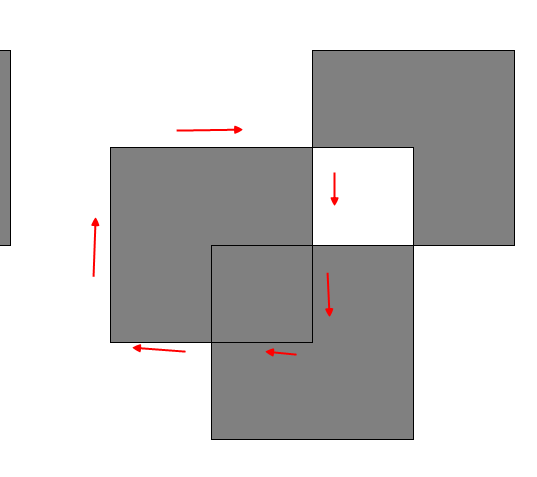
标出方向后,判断某个区域是否被填充,就在该区域内一点向外做射线,如图
这里写图片描述
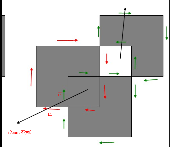
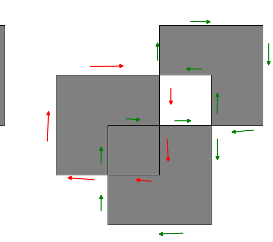
以顺时针或逆时针为+,反向为-,iCount初始为0,图中两次方向相同,iCount不为0,填充,另一区域很容易判断不填充,是不是很简单,
方法二总结:如果穿过奇数条边的话,肯定不会为0,肯定会填充,如果是偶数,再用这种方式判断一下就行了

  • 2
    点赞
  • 6
    收藏
    觉得还不错? 一键收藏
  • 2
    评论
STM32的GPIO共有8种工作模式,分别是输入模式、输出模式、复用功能模式、模拟模式、开漏输出模式、推挽输出模式、复用功能开漏输出模式和复用功能推挽输出模式。 以下是每种模式的写法: 1. 输入模式 ```c GPIO_InitStruct.Pin = GPIO_PIN_0; GPIO_InitStruct.Mode = GPIO_MODE_INPUT; GPIO_InitStruct.Pull = GPIO_NOPULL; HAL_GPIO_Init(GPIOA, &GPIO_InitStruct); ``` 2. 输出模式 ```c GPIO_InitStruct.Pin = GPIO_PIN_0; GPIO_InitStruct.Mode = GPIO_MODE_OUTPUT_PP; GPIO_InitStruct.Pull = GPIO_NOPULL; GPIO_InitStruct.Speed = GPIO_SPEED_FREQ_LOW; HAL_GPIO_Init(GPIOA, &GPIO_InitStruct); ``` 3. 复用功能模式 ```c GPIO_InitStruct.Pin = GPIO_PIN_0; GPIO_InitStruct.Mode = GPIO_MODE_AF_PP; GPIO_InitStruct.Pull = GPIO_NOPULL; GPIO_InitStruct.Speed = GPIO_SPEED_FREQ_LOW; GPIO_InitStruct.Alternate = GPIO_AF1_TIM2; HAL_GPIO_Init(GPIOA, &GPIO_InitStruct); ``` 4. 模拟模式 ```c GPIO_InitStruct.Pin = GPIO_PIN_0; GPIO_InitStruct.Mode = GPIO_MODE_ANALOG; GPIO_InitStruct.Pull = GPIO_NOPULL; HAL_GPIO_Init(GPIOA, &GPIO_InitStruct); ``` 5. 开漏输出模式 ```c GPIO_InitStruct.Pin = GPIO_PIN_0; GPIO_InitStruct.Mode = GPIO_MODE_OUTPUT_OD; GPIO_InitStruct.Pull = GPIO_NOPULL; GPIO_InitStruct.Speed = GPIO_SPEED_FREQ_LOW; HAL_GPIO_Init(GPIOA, &GPIO_InitStruct); ``` 6. 推挽输出模式 ```c GPIO_InitStruct.Pin = GPIO_PIN_0; GPIO_InitStruct.Mode = GPIO_MODE_OUTPUT_PP; GPIO_InitStruct.Pull = GPIO_NOPULL; GPIO_InitStruct.Speed = GPIO_SPEED_FREQ_LOW; HAL_GPIO_Init(GPIOA, &GPIO_InitStruct); ``` 7. 复用功能开漏输出模式 ```c GPIO_InitStruct.Pin = GPIO_PIN_0; GPIO_InitStruct.Mode = GPIO_MODE_AF_OD; GPIO_InitStruct.Pull = GPIO_NOPULL; GPIO_InitStruct.Speed = GPIO_SPEED_FREQ_LOW; GPIO_InitStruct.Alternate = GPIO_AF1_TIM2; HAL_GPIO_Init(GPIOA, &GPIO_InitStruct); ``` 8. 复用功能推挽输出模式 ```c GPIO_InitStruct.Pin = GPIO_PIN_0; GPIO_InitStruct.Mode = GPIO_MODE_AF_PP; GPIO_InitStruct.Pull = GPIO_NOPULL; GPIO_InitStruct.Speed = GPIO_SPEED_FREQ_LOW; GPIO_InitStruct.Alternate = GPIO_AF1_TIM2; HAL_GPIO_Init(GPIOA, &GPIO_InitStruct); ```

“相关推荐”对你有帮助么?

  • 非常没帮助
  • 没帮助
  • 一般
  • 有帮助
  • 非常有帮助
提交
评论 2
添加红包

请填写红包祝福语或标题

红包个数最小为10个

红包金额最低5元

当前余额3.43前往充值 >
需支付:10.00
成就一亿技术人!
领取后你会自动成为博主和红包主的粉丝 规则
hope_wisdom
发出的红包
实付
使用余额支付
点击重新获取
扫码支付
钱包余额 0

抵扣说明:

1.余额是钱包充值的虚拟货币,按照1:1的比例进行支付金额的抵扣。
2.余额无法直接购买下载,可以购买VIP、付费专栏及课程。

余额充值