


#include <inc/mmu.h>		// mmu.h 内含有需要使用的宏定义与函数

# Start the CPU: switch to 32-bit protected mode, jump into C.		// 这些代码的作用为转换到 32 位保护模式,然后跳转到 main.c
# The BIOS loads this code from the first sector of the hard disk into		// BIOS 读取硬盘第一扇区的内容到 0x7c00
# memory at physical address 0x7c00 and starts executing in real mode		// 设置 CS、IP 寄存器,执行实模式
# with %cs=0 %ip=7c00.

.set PROT_MODE_CSEG, 0x8         # kernel code segment selector		// 内核代码段 selector,用于寻找 GDT 条目
.set PROT_MODE_DSEG, 0x10        # kernel data segment selector		// 内核数据段 selector,用于寻找 GDT 条目
.set CR0_PE_ON,      0x1         # protected mode enable flag		// 用于设置 CR0 的 PE 位,目的为开启保护模式

.globl start		// 设置全局符号 start
start:
  .code16                     # Assemble for 16-bit mode		// 16位指令
  cli                         # Disable interrupts		// 屏蔽中断,Bootloader 执行过程中不响应中断
  cld                         # String operations increment		// 从低地址到高地址

  # Set up the important data segment registers (DS, ES, SS).		// 初始化段寄存器
  xorw    %ax,%ax             # Segment number zero
  movw    %ax,%ds             # -> Data Segment		// 数据段寄存器
  movw    %ax,%es             # -> Extra Segment		// 附加段寄存器
  movw    %ax,%ss             # -> Stack Segment		// 栈段寄存器
# Enable A20:
  #   For backwards compatibility with the earliest PCs, physical
  #   address line 20 is tied low, so that addresses higher than
  #   1MB wrap around to zero by default.  This code undoes this.
seta20.1:
  inb     $0x64,%al               # Wait for not busy
  testb   $0x2,%al
  jnz     seta20.1
  movb    $0xd1,%al               # 0xd1 -> port 0x64
  outb    %al,$0x64

seta20.2:
  inb     $0x64,%al               # Wait for not busy
  testb   $0x2,%al
  jnz     seta20.2
  movb    $0xdf,%al               # 0xdf -> port 0x60
  outb    %al,$0x60
在 8086 中有 20 根地址总线,通过 CS:IP 对的方式寻址,最大访问地址为 1MB
然而,FFFFH:FFFFH = 10FFEFH,也就是说从 100000H 到 10FFEFH 无法访问
当访问这段地址时,会产生 wrap-around,也就是实际访问地址会对 1MB 求模
到了 80286 中有 24 根地址总线,最大访问地址为 16MB
这个时候,不会产生 wrap-around,为了向下兼容 8086,需要使用第 21 根地址总线
所以 IBM 的工程师使用 PS/2 Controller 输出端口中多余的端口来管理 A20 gate,也就是第 21 根地址总线(从 0 开始)
在解释上面的代码之前,先看下面一些关于 PS/2 Controller 的资料(表格只列出相关内容,Bit 从 0 开始,即 Bit1 为第二位):
| IO Port | Access Type | Purpose |
|---|---|---|
| 0x60 | Read/Write | Data Port |
| 0x64 | Read | Status Register |
| 0x64 | Write | Command Register |
| Bit | Meaning |
|---|---|
| 1 |
Input buffer status (0 = empty, 1 = full)
(must be clear before attempting to write data to IO port 0x60 or IO port 0x64)
|
| Command Byte | Meaning | Response Byte |
| 0xD1 |
Write next byte to Controller Output Port
Note: Check if output buffer is empty first
| None |
| Bit | Meaning |
|---|---|
| 1 | A20 gate (output) |
第 6 行,inb 指令的意思是从 I/O 读取 1byte 的数据,存入 al 寄存器中,而读取 0x64 端口可以从上表中看出意思是读取状态寄存器的值
第 7 行,testb 指令的意思是对两个操作数执行逻辑 AND 并设置 flags 寄存器,在这里也就是读取 al 寄存器中的数据的第二位是否为 0
第 8 行,jnz 指令的意思是如果不是 0 则跳转到 seta20.1,从上表中可以看出,如果第二位为 0 代表输入缓存为空,即可以向端口 0x60 或者 0x64 写数据
第 9 、10 行,outb 指令德意思是向 I/O 写入 1byte 的数据,也就是向命令寄存器写入 0xD1,即命令 PS/2 Controller 将下一个写入 0x60 的字节写出到 Output Port
第 16 行,将 0xdf 写入 0x60,即将 Output Port 的第二位设置为 1
至此,就打开了 A20 gate
  # Switch from real to protected mode, using a bootstrap GDT
  # and segment translation that makes virtual addresses
  # identical to their physical addresses, so that the
  # effective memory map does not change during the switch.
  lgdt    gdtdesc
  movl    %cr0, %eax
  orl     $CR0_PE_ON, %eax		// 参考文件开头宏定义 CR0_PE_ON = 0x1
  movl    %eax, %cr0

# Bootstrap GDT
.p2align 2                                # force 4 byte alignment
gdt:
  SEG_NULL				# null seg
  SEG(STA_X|STA_R, 0x0, 0xffffffff)	# code seg
  SEG(STA_W, 0x0, 0xffffffff)	        # data seg

gdtdesc:
  .word   0x17                            # sizeof(gdt) - 1
  .long   gdt                             # address gdt
/*
* Macros to build GDT entries in assembly. // mmu.h 中的片段
*/
#define SEG_NULL \
.word 0, 0; \
.byte 0, 0, 0, 0
#define SEG(type,base,lim) \ // 权限状态 基地址 大小
.word (((lim) >> 12) & 0xffff), ((base) & 0xffff); \ // 2 个 word 数据,即前 32 位,详细信息看下文图片
.byte (((base) >> 16) & 0xff), (0x90 | (type)), \ // 4 个 byte 数据,即后 32 位
(0xC0 | (((lim) >> 28) & 0xf)), (((base) >> 24) & 0xff)
// Application segment type bits
#define STA_X 0x8 // Executable segment
#define STA_E 0x4 // Expand down (non-executable segments)
#define STA_C 0x4 // Conforming code segment (executable only)
#define STA_W 0x2 // Writeable (non-executable segments)
#define STA_R 0x2 // Readable (executable segments)
#define STA_A 0x1 // AccessedGDTR 是存放 GDT 地址与大小的寄存器,下图为结构,16 位 Size 代表大小,32 位 Offset 代表线性地址
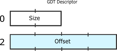
The offset is the linear address of the table itself, which means that paging applies. The size is the size of the table subtracted by 1.
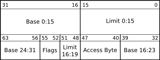
GDT Entry 是 GDT 中存放的条目,大小为 8 个字节,下图为结构,Base 代表段基地址,Limit 代表段大小,其他为一些状态权限相关的信息
第 5 行,lgdt 的作用为设置 GDTR,可以看到 gdtdesc 的信息从第 17 行开始
第 18 行,.word 的作用可以理解为设置一个大小为 word 的数据,由于 0x17 = 23,所以 GDTR 中的 Size 为 24,即存在 3 个 GDT Entry
第 19 行,.long 的作用与 .word 同理,可以看到 gdt 的信息从第 12 行开始
第 13、14、15 行,分别设置了NULL段,代码段,数据段,这里调用了 SEG 函数,相关定义可以从 mmu.h 中找到
上面几行执行的结果大概可以视作如下:
GDT[0] = { base = 0x0, limit = 0x0, type = 0x0 }
GDT[1] = { base = 0x0, limit = 0xffffffff, type = 0xA }
GDT[2] = { base = 0x0, limit = 0xffffffff, type = 0x2 }
回到第 6、7、8 行,通过设置 cr0 寄存器的 PE 位,将 CPU 从 real mode 转换到 protected mode,有关这两个模式的信息请自行上网搜索
.set PROT_MODE_CSEG, 0x8         # kernel code segment selector		// 文件开头的宏定义,代码段的 selector
.set PROT_MODE_DSEG, 0x10        # kernel data segment selector		// 文件开头的宏定义,数据段的 selector

  # Jump to next instruction, but in 32-bit code segment.
  # Switches processor into 32-bit mode.
  ljmp    $PROT_MODE_CSEG, $protcseg

  .code32                     # Assemble for 32-bit mode
protcseg:
  # Set up the protected-mode data segment registers
  movw    $PROT_MODE_DSEG, %ax    # Our data segment selector
  movw    %ax, %ds                # -> DS: Data Segment
  movw    %ax, %es                # -> ES: Extra Segment
  movw    %ax, %fs                # -> FS
  movw    %ax, %gs                # -> GS
  movw    %ax, %ss                # -> SS: Stack Segment
索引,即 GDT 表上的索引,用来获取 GDT 中的条目
TI,若为 1 则代表该条目为 LDT,这里没有用到 LDT,相关信息有兴趣可以到网上搜索
RPL,权限等级
接下来看代码:
第 6 行,ljmp 的作用为跳转到指定地址,可以看到 PROT_MODE_CSEG = 0x8 = 0000000000001000,即索引 = 1,TI = 0,RPL = 0
由于在保护模式下,根据上文得出的条目得知 GDT[1] = { base = 0x0, limit = 0xffffffff, type = 0xA }
所以线性地址为 0H + protcseg 的地址 = protcseg 的地址,即跳转到 protcseg 的地址(第 9 行)
第 8 行,代表下面的指令为 32 位指令
第 11 行,与第 6 行同理,得到 GDT[2] = { base = 0x0, limit = 0xffffffff, type = 0x2 } ,然后接下来的几行分别设置各个段寄存器
  # Set up the stack pointer and call into C.
  movl    $start, %esp		// 设置栈指针
  call bootmain		// 调用 bootmain 函数,位于 main.c

  # If bootmain returns (it shouldn't), loop.
spin:
jmp spin参考资料:
http://wiki.osdev.org/%228042%22_PS/2_Controller
http://www.win.tue.nl/~aeb/linux/kbd/A20.html
http://wiki.osdev.org/GDT
http://www.csie.ntu.edu.tw/~wcchen/asm98/asm/proj/b85506061/chap2/segment.html


 被折叠的 条评论
为什么被折叠?
被折叠的 条评论
为什么被折叠?
 到【灌水乐园】发言


