


FPGA电路逻辑的Verilog HDL编程方式设计与验证
上一篇是讲述了原理图的设计方式,这次使用Verilog HDL编程的方式进行设计和验证, 在EDA工具中重新应用一次。
- 实验1:拼接 4-16译码器
- 实验2A : 设计M=12的计数器
- 实验2B : 设计M=20的计数器
- 0-9往复的计数器
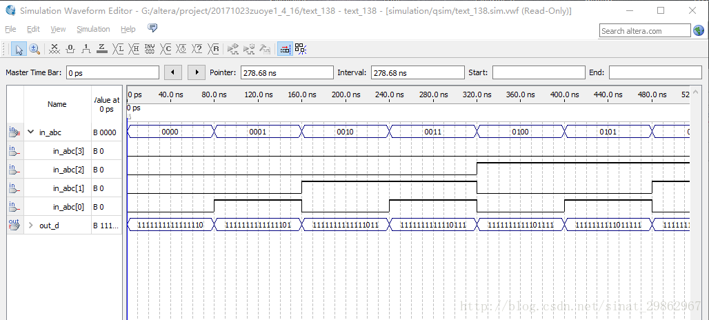
实验1:拼接 4-16译码器
Verilog HDL设计4-16译码器:
module text_416(in_abc, out_d);
    input [3:0] in_abc;
    output  out_d;
    reg[15:0] out_d;

    always@(in_abc)
        begin
            case(in_abc)
                4'b0000 : out_d = 16'hfffe;
                4'b0001 : out_d = 16'hfffd;
                4'b0010 : out_d = 16'hfffb;
                4'b0011 : out_d = 16'hfff7;
                4'b0100 : out_d = 16'hffef;
                4'b0101 : out_d = 16'hffdf;
                4'b0110 : out_d = 16'hffbf;
                4'b0111 : out_d = 16'hff7f;
                4'b1000 : out_d = 16'hfeff;
                4'b1001 : out_d = 16'hfdff;
                4'b1010 : out_d = 16'hfbff;
                4'b1011 : out_d = 16'hf7ff;
                4'b1100 : out_d = 16'hefff;
                4'b1101 : out_d = 16'hdfff;
                4'b1110 : out_d = 16'hbfff;
                4'b1111 : out_d = 16'h7fff;

            endcase
        end

endmodule
仿真结果如下图:
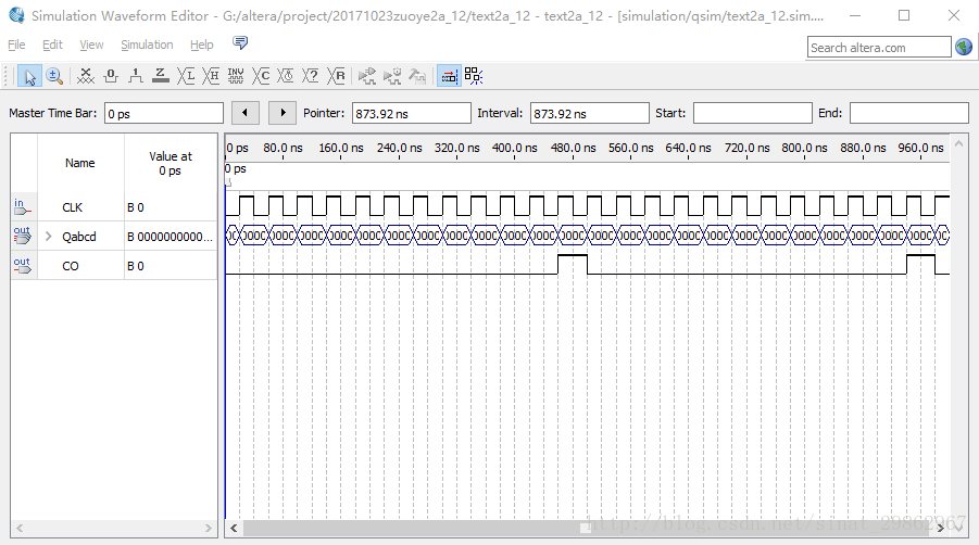
实验2A : 设计M=12的计数器
Verilog HDL设计M=12计数器:
module text2a_12(CLK, Qabcd, CO);
    input CLK;
    output Qabcd,CO;
    reg[3:0] Qabcd,count;
    reg CO;

    always@(posedge CLK )
        begin
            if(count==11)
                    count <= 0;
            else
                    count <= count + 1 ;
        end
    always@(count )
        begin
            Qabcd = count;
            if(count == 11)
                CO = 1;
            else  CO= 0;
        end


endmodule
仿真结果如下图:
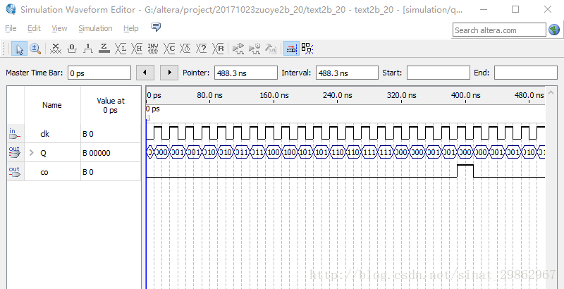
实验2B : 设计M=20的计数器
Verilog HDL设计M=20计数器:
module text2b_20(clk,Q,co);
    input clk;
    output Q,co;
    reg[4:0] Q,count;
    reg co;

    always@(posedge clk )
        begin
            if(count == 19)
                    count <= 0;
            else
                    count <= count + 1;
        end
    always@(count)
        begin
            Q = count;
            if(count==19)
                CO = 1;
            else  CO = 0;
        end

endmodule
仿真结果如下图:
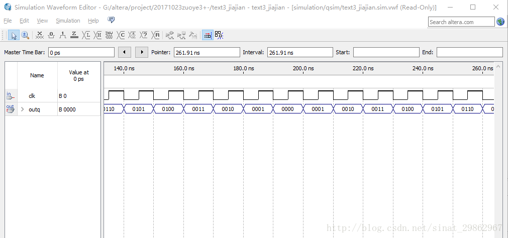
附加实验 : 设计0-9往复计数器
Verilog HDL设计0-9往复计数器:
module text3_jiajian(clk,outq);
    input clk;
    output outq;

    reg[3:0] outq;
    reg[3:0] count;
    reg[3:0] count1;

    always @ ( negedge clk )
        begin
            if(count1 == 0)
                begin
                    count <= count + 1;
                    if(count == 10)
                        begin
                            count1 <= count;
                            count <= count - 1;
                        end
                end
            if(count1 == 10)
                begin
                    count <= count - 1;
                    if(count == 0)
                        begin
                            count1 <= count;
                        end
                end

            outq <= count;
        end
endmodule
仿真结果如下图:
通过以上实验,可以看到,使用FPGA芯片,可以用Verilog HDL语言进行编程实现,能够直接对电路功能进行设计, 更直接明了。


 4212
4212


 被折叠的 条评论
为什么被折叠?
被折叠的 条评论
为什么被折叠?
 到【灌水乐园】发言


