


This article originally appeared in Circuit Celler.
COM ports have long provided a convenient way for PCs and embedded systems to exchange information. The traditional COM port on a PC is an RS-232 serial port on a motherboard or expansion card. Recent PCs often skip RS-232 in favor of USB. But with the right firmware, a USB device can appear as a virtual COM port that applications can access using .NET's SerialPort class or other COM-port APIs or libraries.
This article will show how to design and program a USB virtual COM-port device using a general-purpose microcontroller with an embedded or external USB controller. The device uses standard USB class drivers included with Windows and other OSes.
Options for Devices
The COM-port software interface provides a way for PCs to exchange data with devices for any purpose. A classic example is a modem that enables a PC to send and receive data over phone lines and responds to AT (Hayes modem) commands from the PC. Other COM-port devices support vendor-specific command sets for data acquisition, motor control, or other uses.
To communicate with a COM port, an application first reserves the resource by opening the port. For many devices, an application can also get and set port parameters such as bit rate, number of data bits per word, and flow-control method. The application reads and writes to the port as needed and when finished communicating, closes the port to allow other applications access to it.
A USB virtual COM port is a software interface that enables applications to access a USB device as if it were a built-in serial port. Many USB virtual COM-port devices function as bridges that convert between USB and RS-232 or other asynchronous serial interfaces.
But a virtual COM port doesn’t have to have a serial interface at all. Some virtual COM-port devices convert between USB and a parallel interface. Or a device might just read and store sensor data from an on-chip analog port and send the data to a PC via USB.
One way to create a virtual COM-port device is to use a dedicated chip such as FTDI’s FT232R USB UART. The chip handles all USB-specific communications in hardware and has an asynchronous serial port that can interface to a port on a microcontroller. FTDI provides drivers for Windows and other OSes. A similar chip is FTDI’s FT245R USB FIFO, which has a parallel interface instead of the serial port.
These chips are a quick way to add a USB port to a design. Many existing devices with asynchronous serial ports can use a USB UART to convert to USB with no firmware changes. Other companies with UART bridge chips include MosChip Semiconductor Technology Ltd., Prolific Technology, and Silicon Laboratories.
The device I’ll describe takes a different approach. The design doesn’t require a specific vendor’s USB controller or driver. The device can use a general-purpose microcontroller with an embedded USB controller or a CPU that interfaces to an external USB controller. The USB port can be full or high speed. Device firmware manages USB communications and whatever other tasks the device is responsible for.
Instead of a vendor-specific driver, the PC uses the USB communication devices class (CDC) driver included with Windows and other OSes. For Windows, an INF file matches the driver to the device.
Several microcontroller vendors provide example firmware for USB virtual COM ports. The chips include Atmel Corporation’s AT89C5131, Microchip Technology’s PIC18F4550, and NXP Semiconductors’ LPX214x. These examples are good starting points for projects.
If you don’t have CDC example code for your CPU, you can base your firmware on other example code that transfers data using bulk or interrupt transfers. Any complete example firmware includes code for returning descriptors and responding to other control transfers and events on the bus. At the device, bulk and interrupt transfers are identical. The only difference is in how the host schedules the transfers.
Duties of Firmware
For a quick review of USB basics, see the sidebar, “1-minute USB Crash Course.” USB CDC firmware for a generic COM-port device performs several tasks.
During enumeration, the firmware responds to requests for descriptors that identify the device’s CDC function.
The device receives COM-port data following OUT token packets addressed to the bulk OUT endpoint and sends COM-port data or NAK in response to IN token packets addressed to the bulk IN endpoint.
To send status information, the device returns notification data in response to IN token packets on the interrupt IN endpoint. A device with no information to send returns NAK. Most devices also respond to class-specific control requests that set and get serial-port parameters.
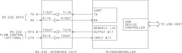
Figure 1. A microcontroller with a UART and an embedded USB device controller can function as a USB/RS-232 bridge. The RS-232 port in this example includes two data lines and two lines for flow control.
Figure 1 shows a CDC device that functions as a USB to RS-232 bridge. The microcontroller’s asynchronous serial port interfaces to a Maxim MAX232 or similar RS-232 converter. Microcontrollers generally don’t have dedicated port bits for RS-232’s status and control signals, but a device can use any spare port bits for needed signals. Typical RS-232 signals used for flow control are RTS and CTS.
The bridge performs the function of an RS-232 port on the host PC. The TX and RTS signals are outputs, and RX and CTS are inputs. In RS-232 lingo, the port is configured as a DTE.
The RS-232 interface can connect to a serial port on a microcontroller, another component with a serial interface, or a (via a null-modem cable). For cables of up to 4000 ft, use a full-duplex RS-422 interface chip such as a Maxim MAX3087. For a serial network, use an RS-485 transceiver in place of the MAX232.
If unneeded for modem control, the RS-232 signals DTR, DSR, RI, and CD can serve as general-purpose I/O bits or remain unused.
Customizing the Descriptors
The USB 2.0 specification defines the content and format of standard USB descriptors. The CDC specification defines additional class-specific descriptors.
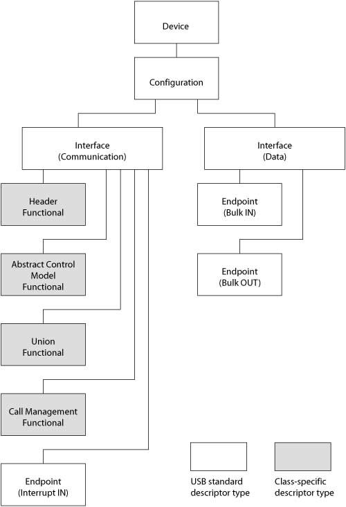
Figure 2. A USB virtual COM-port device can use the USB CDC class drivers provided by Windows and other OSes. A device that exchanges vendor-defined data can use these descriptors.
Figure 2 shows the descriptors in a typical CDC device that functions as a generic virtual COM port. I’ll focus on device-specific items you may need to change from values in example firmware.
Every USB device has a device descriptor (Listing 1).
// Device descriptor
rom USB_DEV_DSC device_dsc=
 {
 0x12,            // Descriptor size in bytes
 0x01,            // DEVICE descriptor type
 0x0200,          // USB version, BCD (2.0)
 0x02             // Class: CDC
 0x00,            // Subclass: none
 0x00,            // Protocol: none
 0x08,            // Max. packet size, Endpoint 0
 0x0925,          // USB Vendor ID
 0x9060,          // USB Product ID
 0x0100,          // Device release, BCD (1.0)
 0x00,            // Manufacturer string index
 0x00,            // Product string index
 0x01,            // Serial number string index
 0x01             // Number of configurations
 };
Listing 1. The device descriptor names the communication devices class (CDC).
The class code specifies CDC as the device’s class. The Vendor ID and Product ID values identify the specific device. Every device with the same Vendor ID/Product ID pair should use the same driver on the host.
The serial-number string index identifies a descriptor that contains a serial number. A serial number prevents unwanted “COM-port proliferation.” A device with a serial number retains its COM-port number if moved to a different USB port on a Windows PC. A device that doesn’t contain a serial number gets a new port number on each attachment to a different port on a PC.
Besides a device descriptor, a typical CDC virtual COM-port device has one configuration descriptor and two interface descriptors. Each interface descriptor has subordinate descriptors.
The configuration descriptor specifies power requirements and the number of interfaces in the configuration. The interface descriptors tell the host how the device implements its communication functions.
The communication interface descriptor names a CDC subclass and protocol (Listing 2).
// Communication interface descriptor
0x09,            // Descriptor size in bytes
 0x04,            // INTERFACE descriptor type
 0x00,            // Interface number
 0x00,            // Alternate setting number
 0x01,            // Number of endpoints
 0x02,            // Class: CDC communication
 0x02,            // Subclass: abstract control model
 0x02,            // Protocol: V.25ter (AT commands)
 0x00,            // Interface string index
Listing 2. The communication interface provides an interrupt endpoint for sending notifications to the USB host.
Generic COM-port devices and some modems belong to the abstract control model subclass. The protocol is V.25ter, which documents common AT commands. For compatibility with standard host drivers, a generic virtual COM-port device should specify the V.25ter protocol even if the device doesn’t use AT commands.
The communication interface has four class-specific descriptors and an endpoint descriptor. The header functional descriptor names the version of the CDC specification the interface complies with. The abstract control model descriptor specifies what class-specific requests and notifications the device supports. (More on those below.) The union functional descriptor identifies the interfaces that belong to the CDC function, which are typically the communication interface plus a data interface. The call management functional descriptor tells how the device manages calls. Because a generic COM-port device has no calls to handle, the descriptor says the device doesn’t handle call management.
An interrupt endpoint sends status notifications to the host. The endpoint descriptor provides the endpoint’s number, direction, and wMaxPacketSize.
The data interface is responsible for sending and receiving the COM-port data. The interface descriptor (Listing 3) tells the host the interface has two bulk endpoints, one for each direction. Each endpoint has an endpoint descriptor.
// Data interface descriptor
0x09,            // Descriptor size in bytes
 0x04,            // INTERFACE descriptor type
 0x01,            // Interface number
 0x00,            // Alternate setting number
 0x02,            // Number of endpoints
 0x0a,            // Class: CDC data
 0x00,            // Subclass: none
 0x00,            // Protocol: none
 0x00,            // Interface string index
Listing 3. The data interface provides two endpoints for sending and receiving COM-port data.
After retrieving the descriptors from the device and assigning the CDC driver, the host polls the bulk IN endpoint for COM-port data and polls the interrupt IN endpoint for notification data. An endpoint with no data to send returns NAK in response to received IN token packets.
When sending COM-port data to the host, a device indicates the end of a transfer by sending a short packet, which is a data packet containing less than wMaxPacketSize bytes. If the entire transfer is less than wMaxPacketSize, the transfer’s only data packet is a short packet. If the transfer consists of more than wMaxPacketSize bytes, only the transfer’s final data packet is a short packet.
When a transfer has an exact multiple of wMaxPacketSize bytes, the endpoint returns wMaxPacketSize bytes in one or more transactions until all of the data has been sent. The endpoint then indicates the end of the transfer by responding to an IN token packet with a zero-length packet (ZLP), which is a data packet with no data bytes.
On a Windows host, every CDC virtual COM-port device must have an INF file that contains the Vendor ID and Product ID values and names the software driver for the device. Windows doesn’t provide a generic INF file for USB virtual COM-port devices as it does for other device types, such as mass storage and human interface devices (HIDs).
You can modify an INF file provided with CDC example code. Listing 4 is an INF-file excerpt that specifies a Vendor ID and Product ID for a device.
[Manufacturer]
 %MFGNAME%=Lakeview
[Lakeview]
 %DESCRIPTION%=DriverInstall, USB\VID_0925&PID_9060
Listing 4. The INF file for a CDC device must include the device’s USB Vendor ID (VID) and Product ID (PID). In this excerpt, VID = 0925h and PID = 9060h.
Setting Port Parameters
Besides COM-port data, devices with asynchronous serial ports often exchange information relating to port parameters, status and control signals, and error states. The host uses class-specific requests and notifications to send and receive the information. Devices that don’t have asynchronous serial ports don’t need to support these requests and notifications.
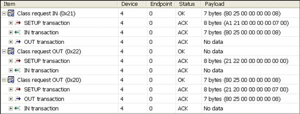
Figure 3. The USB communication devices class defines requests that set and get port parameters and control-line states. (Ellisys USB Explorer USB analyzer display)
The SET_LINE_CODING and GET_LINE_CODING requests set and request the bit rate, number of Stop bits, parity, and number of data bits. Figure 3 shows host and device data for these requests. The second byte in the Setup transaction is the request number.
When an application changes a port’s parameters, the host issues a SET_LINE_CODING request (20h) to the device.
The OUT transaction contains the line-coding data. The values 80 25 in the first two bytes indicate a requested bit rate of 2580h, or 9600 bps. The value 08 in the final bytes is the number of data bits per transmitted word on the serial port. On receiving the parameters, the device implements any requested changes. The IN transaction of the transfer is the Status stage. The device indicates success by returning a ZLP (no data).
Request 21h is GET_LINE_CODING. The device sends its current parameters in the IN transaction. The OUT transaction is the Status stage, where the host indicates success by sending a ZLP.
In the SET_CONTROL_LINE_STATE request (22h), the host tells the device how to set the RS-232 control signals RTS and DTR. The host sends the control-line states in the third byte of the Setup transaction. Bit 0 is the state of DTR, and bit 1 is the state of RTS. Device firmware detects the request, accepts the data, and implements any changes to the bits. The IN transaction is the Status stage. The device indicates success by returning a ZLP.
The SEND_BREAK request (23h) requests the device to send an RS-232 break signal (a positive RS-232 voltage on the TX line) for a specified number of milliseconds. If the requested value is FFFFh, the device should maintain the break signal until receiving another SEND_BREAK request with a value of 0000h. In .NET’s SerialPort class, setting the BreakState property causes the host to send this request with a value of FFFFh or 0000h.
The SERIAL_STATE notification provides a way for a device to send the states of the RS-232 status signals RI, DSR, and CD, the Break state, and error states for buffer overrun, parity error, and framing error. The notification consists of an 8-byte header and two notification bytes. The interrupt IN endpoint returns a notification or NAK in response to received IN token packets.
The notification doesn’t include the state of RS-232’s CTS status signal. Device firmware can still read CTS on a local asynchronous port and take action as needed. For example, if a virtual COM-port device has data to send to a remote device that hasn’t asserted CTS, the virtual COM-port device can store the data in a buffer and wait to transmit.
If the buffer is full, the virtual COM-port device can NAK attempts by the USB host to send more data. When the remote device asserts CTS, the virtual COM-port device can send the buffered data and accept new data from the host. To use CTS in this way, the USB host doesn’t need to know the state of CTS.
If you want to use CTS in an unconventional way, such as having a host application read a switch state on a device, you’re out of luck with the CDC driver unless you can define a vendor-specific command that travels on the same bulk pipes that carry application data.
Two CDC requests (SEND_ENCAPSULATED_COMMAND and GET_ENCAPSULATED_RESPONSE) and one notification (RESPONSE_AVAILABLE) relate to AT commands. The CDC specification requires abstract control model devices to support the requests and notification. A typical generic COM-port device doesn’t connect to a modem that supports AT commands. For these devices, the host will never send the requests or require the notification data, so device firmware doesn’t need to implement them.
Maximizing Performance
These guidelines can improve performance of device firmware:
For full-speed devices, set wMaxPacketSize in the bulk endpoint descriptors to 64 to enable transferring the most data possible in each USB transaction. With a UHCI host controller, if a full-speed bulk endpoint’s wMaxPacketSize is less than 64, the host controller schedules no more than one transaction per millisecond for the endpoint. (Full-speed host controllers comply with either the OHCI or the UHCI standard. Many PC motherboards contain UHCI controllers.) High-speed bulk endpoints must set wMaxPacketSize = 512.
To transfer large amounts of data to the host as quickly as possible, use wMaxPacketSize data packets. Larger packets mean fewer transactions are needed to transfer the data.
When sending data to the host in multiple transactions, avoid returning NAK. Immediately after sending a packet of data, refill the endpoint buffer and arm the endpoint for the next transaction. For the fastest response, configure the endpoint to trigger an interrupt after sending data.
When receiving data from the host, avoid returning NAK. Immediately after receiving a packet of data, retrieve the data from the endpoint buffer and arm the endpoint for the next transaction. For the fastest response, configure the endpoint to trigger an interrupt on receiving data.
On the host, be aware that setting RS-232 control lines or changing the parity type or other parameters can be slow compared to performing the same operations on an internal serial port. To perform these actions on a USB virtual COM-port device, the host must send a request in a control transfer.


 4458
4458


 被折叠的 条评论
为什么被折叠?
被折叠的 条评论
为什么被折叠?
 到【灌水乐园】发言


