


3. Lighting Model
In the previous section we considered the simplest (but at the same time correct) way of imposing cube texture on the object. Now I propose to deal with the object lighting.
As I said earlier in the window light, we need to forget about Lambert lighting model. In one of the best models BSSRDF (subsurface dissipation), but only if the simulated matt (opaque glass) can be used to model the diffuse light. This we will not do, and better analyze specular (specular) component of light. I suggest using one of the simple but high-quality specular lighting models - Cook-Torrance model [3].
It will be convenient to make a code for calculating the specular component in a separate function. Let us briefly consider a model lighting the Cook-Torrance (in terms of the scalar product of vectors, instead of angles). We assume that N - is normal at the point, V - normalized view vector, L - normalized vector from the light source to the top, H - normalized vector sum of L and V.
Thus, the amount of reflected light in the Cook-Torrance model depends on three factors:
1. Fresnel coefficient (F)
2. The geometric component, taking into account the self-shadowing (G)
3. A component that takes into account the roughness of the surface (D)
The general formula for the calculation of the reflected light is as follows:
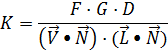
Fresnel factor we have already calculated before, so consider calculating the geometric component:
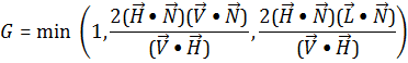
The component that takes into account the surface roughness - the distribution micrograin surface for a more accurate accounting of the reflected light from them. Generally, for the calculation of the component distribution using Beckman:
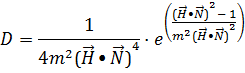
where the parameter m (0 to 1) determine the surface roughness. Than it is, the roughened surface Bole, and thus reflects light even at wide angles. Let it be written in the form of a function in the language GLSL:
  float CookTorrance (vec3 _normal, vec3 _light , vec3 _view, float _fresnel, float _roughness)
 {
   vec3 half_vec = normalize (_view + _light);  // Vector H
    // Now calculate the range of the scalar products
   float NdotL = max (dot (_normal , _light), 0.0);
   float NdotV = max (dot (_normal , _view), 0.0);
   float NdotH = max (dot (_normal , half_vec), 1.0e- 7);
   float VdotH = max (dot (_view , half_vec), 1.0e- 7);

   // Geometric component
   float geometric = 2.0 * NdotH / VdotH ;
   geometric = min (1.0, geometric * min (NdotV, NdotL));

   // roughness
   float r_sq = _roughness * _roughness;
   float NdotH_sq = NdotH * NdotH;
   float NdotH_sq_r = 1.0 / (NdotH_sq * r_sq);
   float roughness_exp = (NdotH_sq - 1.0) * (NdotH_sq_r);
   float roughness = 0.25 * exp (roughness_exp ) * NdotH_sq_r / NdotH_sq;

   // Final result
   return min (1.0, _fresnel * geometric * roughness / (NdotV + 1.0e- 7));
 }
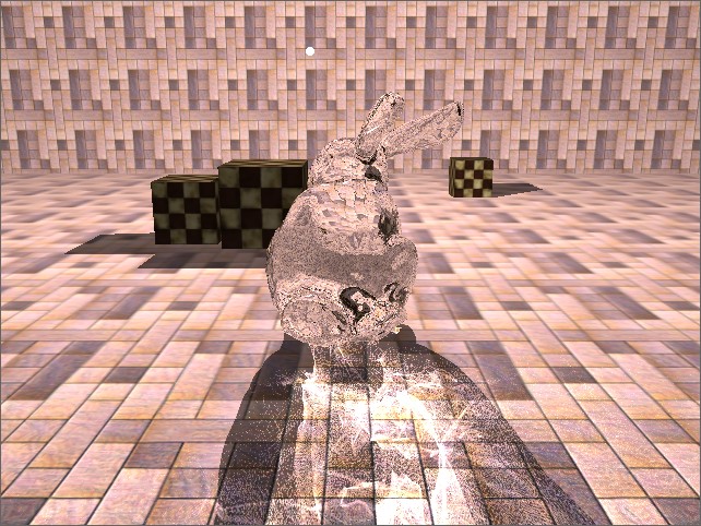
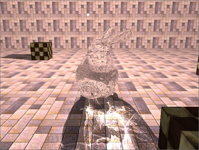
Let's take a different roughness factors and see the results below:
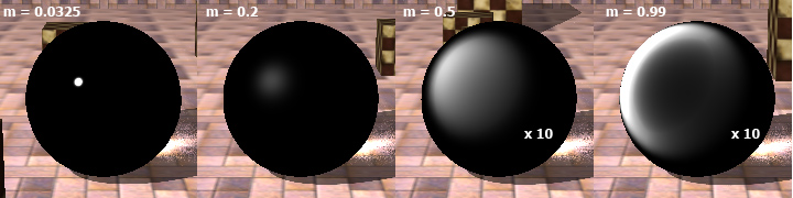
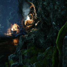
The lower the roughness - the more concentrated spot of light. Larger values of roughness suitable for metals, so our choice - a small ratio (<0.1). In this case, the material will look like polished glass, to which we aspire. Well, actually, and all the lights on the model. In the next section we will be global illumination - namely modeling the caustic.
4. Modelling of the caustic
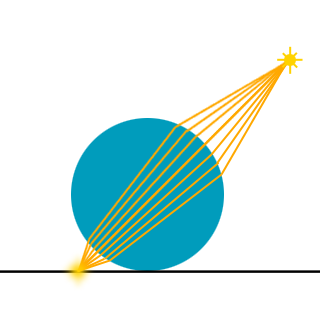
So, it remains to consider another effect, which will complement our simulation of glass - caustic. Caustic - is concentrated in a small area of light rays, thereby increases the brightness of the subjects in this area. Let's look at the process of formation of the caustic. The light rays are refracted at the interface of two materials, deviate from its initial course and due to the geometry of the object may fall after refraction in a small area (focus). Schematically it can be represented as follows:
Thus, in order to build the image of the caustic, we need:
1. find the direction of the beam after refraction at the transition from air to material
2. Since we are modeling glass objects, then we also need to find the direction of the beam at the output of the object
3. To find the point of intersection of the refracted beam to the geometry on which the beam will fall
To simulate the caustics I suggest using a photon map in space the image (Image Space Photon Mapping). I think we should give a brief explanation of the technique. When building a photon map we draw the image as it were, on points, each of which represents one photon (or a ray of light, if you will). This method allows us to calculate the position and direction of movement of photons (light rays) after refraction, as well as the intersection of photons with scene objects without information about their original geometry (that is, we do not check the intersection of rays with triangles, and all the calculations we perform, based on from pre-generated textures).
In this method, all calculations are done in the vertex shader, so we need the support of graphics technology Vertex Texture Fetch (a sample of a texture in the vertex shader). The result of the calculations is the texture that contains lighting, taking into account the photon trajectories rejected. This texture, we will continue to impose on the projective our scene.
So let's start to consider this method in order. First we need to create a vertex buffer that we will display on the drawing as a photon map. Draw the buffer we will point, with the original provisions of the vertices will play the role of texture coordinates for a sample of texture. It creates a buffer is very easy - you need to locate peaks in the range of zero to one, with a shift to half a pixel to avoid the appearance of black (empty) strips on the sides:
  // At the entrance - a buffer name and "density" (eg 1024x1024)
 Ce2Buffer * Ce2Render :: createPhotonMap (const string & name, const vec2i & size)
 {
   int numPhotons = size.x * size.y;  // Calculate the number of photons points
   vec2 texel = vec2 (1.0f / size.x, 1.0f / size.y);
   vec2 dxdy = vec2 (0.5f / size.x, 0.5f / size.y);

   vec2 * photons = new vec2 [numPhotons ];
   Index * indices = new Index [numPhotons ];

   int k = 0;
   for (int i = 0; i <size.y; ++ i)
   for (int j = 0; j <size.x; ++ j)
     {
       photons [k] = vec2 (j * texel.x, i * texel.y) + dxdy;
       indices [k] = k;
       k ++;
     }

   Ce2Buffer * photonBuffer = createVertexBuffer (name, vec2 :: getRA (), numPhotons, photons, numPhotons, indices, GL_POINTS);

   ...

   return photonBuffer;
 }
Now we have a buffer. If his lead on rendering to a texture with a simple shader type:
   in vec2 Vertex;
   ...
   gl_Position = vec4 (Vertex, 0.0, 1.0);
we obtain a uniform filling texture. If it is projective to impose on the scene, it will look like a uniform illumination.
So we need to find a distorted trajectory of photons and their intersection with the geometry of the scene. To do this we need to make three additional rendering pass. Firstly, we need information about the refractive object (glass) - its position in space and the normal. The first pass - a rendering of the light source positions in the texture of the glass object with our normal recording and depth. Depth, we need to restore the situation to further an object in space by using the inverse transform matrix. To calculate the refractive index of the second, we will need to know the position and normal rear edges of the object. The second pass is rendering the rear edges of the object (with a cut-off of the front) with the same record, and normal depth. And the third pass we write the depth of the scene, which will seek photons crossing. In this passage we do not need to write any normal or the color of the objects, but only the depth of the light source position. Therefore, recording in color buffer can be generally disabled in this case. As for the normal size textures I chose RGBA16F - 4-component floating point texture and half-precision (a precision we would be missed).
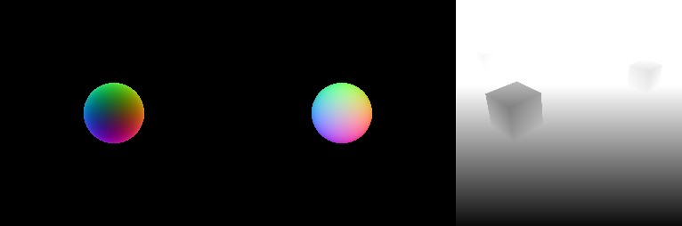
From left to right: back faces refractive object, the front face of the scene depth
Actually these five textures (2 normals and 3 deep) will be enough to get the texture of the caustic (for caustic texture I chose a one-component floating point texture and half-precision - R16F):
Since the direction of the light rays after refraction depends on the properties of the material (in particular the refractive index), it will be in the alpha-channel texture with normals refractive index record. By doing so, we can then calculate a single pass photon map for multiple objects with different refractive indices. The fragment shader to write normal and the refractive index is as follows:
  uniform float indexOfRefraction;
  in vec3 vNormalWS;
  out vec4 FragColor;
  void main ()
    {
    vec3 vNormal = normalize (vNormalWS);
    FragColor = vec4 (vec3 (0.5) + 0.5 * vNormal, indexOfRefraction);
    }
Now a little about finding the intersection of the beam to the geometry in the space of the screen. The basic idea is the numerical solution of the equation:
d - d * = 0
where d - the position of the photon, d * - the position of objects in the scene, read from the texture and depth of recovery by multiplying by the inverse matrix of the projection.
We successively (iteratively) approaching the intersection finding, the number of iterations in the applicable method is small. The essence of the method is as follows: initially, we know the position and direction (normalized vector) beam. To find the intersection of we project the end of this vector on texture, read from it the value, restoring the position of read points in world coordinates, find the distance between the read point and the source, and then move the point along the direction of this distance and repeat steps (that is, again projecting -> read -> restore -> find the distance). After several iterations, we arrive at the point of intersection. I propose to make the intersection being in the function and see it:
  // Function that at a given point, the projection matrix, inverse matrix and texture depth
  // Restores the old value from that projected on the texture coordinates of the given point
 vec3 reproject (vec3 position, mat4 projection, mat4 inverseProjection, sampler2D depthmap)
 {
   // Projecting point
   vec4 vProjected = projection * vec4 (position, 1.0);
   vec2 texCoord = vProjected.xy / vProjected.w;
   // Read the value of the texture
   float fSampledDepth = 2.0 * texture (depthmap , vec2 (0.5) + 0.5 * texCoord) .x - 1.0;
   // Restore the position in world coordinates
   vec4 vWorldSpaceVertex = inverseProjection * vec4 (texCoord, fSampledDepth, 1.0);
   return vWorldSpaceVertex.xyz / vWorldSpaceVertex.w;
 }

 // Function that finds the intersection of the beam issued from a given point in a given direction
 vec3 estimateIntersection (vec3 startPoint, vec3 ray, mat4 projection, mat4 inverseProjection, sampler2D depthmap)
 {
   // first approach
   vec3 p = reproject (startPoint + ray, projection, inverseProjection, depthmap);
   // Iterative calculation of intersection
   for (int i = 0; i <5; ++ i)
       p = reproject (startPoint + ray * distance (startPoint, p), projection, inverseProjection, depthmap);
   return p;
 }
Some notes on the number of iterations: they should not be too small (for example 2 or 3.), But do not need too many (eg 20 or more.). The difference between two and five iterations is much greater than between five and fifty. In the case of a small number of iterations - the intersection is found wrong.
So, I think it's time to come close to calculating caustics. Most understood to be bringing the code with explanations. Let's start looking at our shader. Five of textures that we have prepared:
  uniform sampler2D refractive_normals;
  uniform sampler2D refractive_depth;
  uniform sampler2D receiver_depth;
  uniform sampler2D refractive_backface_normals;
  uniform sampler2D refractive_backface_depth;
Next, we need to position the camera (since we draw from the position of the light source, the position of the camera coincides with it), the projection matrix and the inverse matrix of the projection:
  uniform vec3 vCamera;
  uniform mat4 mModelViewProjection;
  uniform mat4 mInverseModelViewProjection;
Write a function that will read the position of the object from the refracting texture depth and to restore his world coordinates:
  vec3 sampleRefractivePosition (vec2 texCoords, sampler2D depthmap)
  {
    // Read depth
    float fSampledDepth = 2.0 * texture (depthmap , texCoords) .x - 1.0;
    // Restore the world coordinates
    vec4 vWorldSpaceVertex = mInverseModelViewProjection * vec4 (2.0 * texCoords - vec2 (1.0), fSampledDepth, 1.0);
    return vWorldSpaceVertex.xyz / vWorldSpaceVertex.w;
  }
The input we receive vertex shader vertex buffer you created earlier, at the output - the color of the apex:
  in vec2 Vertex;
  out vec4 LightColor;

  // Now the main part
  void main ()
  {
    LightColor = vec4 (1.0);  // Is a constant
    ...
  }
Remember that we Vertex acts as texture coordinates? These texture coordinates, we read from the texture with depth, containing a refractive object, and if the depth is equal to one, then at this point there is no refractive object, and we do not need to carry out all the calculations - just transform the vertex position of [0..1] in the [-1 ..1], we write it and get out of the shader:
  if (texture (refractive_depth, Vertex) .x == 1.0)
  {
    gl_Position = vec4 (2.0 * Vertex - vec2 (1.0), 0.0, 1.0);
    return;
  }
Another test is to cut unnecessary calculations. We read from the normal texture and refractive index (remember, it is written in our alpha channel) refractive object and if it is equal to one - so the object does not refract light rays and can just record the position of the top and get out of the shader:
  vec4 vSampledNormal = texture (refractive_normals, Vertex);
  if (vSampledNormal.a == 1.0)
  {
    gl_Position = vec4 (2.0 * Vertex - vec2 (1.0), 0.0, 1.0);
    return;
  }
So, we finally got to the main part of the shader.
  // First point - we find the position of the refracting object in world coordinates:
  vec3 vRefractivePosition = sampleRefractivePosition (Vertex, refractive_depth);
  // Second paragraph - restore the normal of [0..1] in [-1..1]:
  vec3 vNormal = 2.0 * vSampledNormal.xyz - vec3 (1.0);
  // Third point - we find the original direction of the light beam:
  vec3 vLightVector = normalize (vRefractivePosition - vCamera);
  // Point fourth - find the refracted light beam direction vector:
  vLightVector = refract (vLightVector, vNormal, vSampledNormal.a);

  // If we do not calculate two index, then simply
   // Find the ray intersection with the geometry of the scene and record it
  vec3 vIntersectedVertex = estimateIntersection (vRefractivePosition, vLightVector,
				 mModelViewProjection, mInverseModelViewProjection, receiver_depth);
  gl_Position = mModelViewProjection * vec4 (vIntersectedVertex, 1.0);

  // In the case of two refractions we will need to find
   // The intersection of the refracted ray with the rear edges of the object:
  vec3 vFirstIntersectedVertex = estimateIntersection (vRefractivePosition, vLightVector,
				      mModelViewProjection, mInverseModelViewProjection, refractive_backface_depth);
  // Projected intersection point and find new texture coordinates for the sample:
  vec4 vProjectedIntersection = mModelViewProjection * vec4 (vFirstIntersectedVertex, 1.0);
  vec2 vProjectedIntersectionTC = vec2 (0.5) + 0.5 * vProjectedIntersection.xy / vProjectedIntersection.w;
  // Read from the normal texture of the rear face:
  vec3 vBackfaceSampledNormal = vec3 (1.0) - 2.0 * texture (refractive_backface_normals, vProjectedIntersectionTC) .xyz;
Please note that we are back to the brink, we write the normal, which "looks from the object", and to find the refracted ray we need a normal, which will be directed into the object, so we take the sign "minus" to normal. Next we need to find a ray of refracted a second time:
vLightVector = refract (vLightVector, vBackfaceSampledNormal, 1.0 / vSampledNormal.a);
Again, notice your attention - in this case, the beam emerges from the material into the air, so the refractive index is 1 / η.
It should digress and turn again to the physics. The fact that in the case when the beam goes out of a material with a high refractive index into a medium with a lower refractive index such phenomenon may occur as a total internal reflection (i.e., the light beam is totally reflected from the inside surface of the material and does not go out). This happens when the sine of the angle of incidence greater than the ratio of the smaller to the larger refractive index indicator.
Of course, we would like to take this into account, but we do not have to check the angle of incidence, as the built-in GLSL refract function in the case of total internal reflection returns vec3 value (0.0). That is, we should just check the return value:
  if (dot (vLightVector, vLightVector) <1.0e- 5)
  {
    LightColor = vec4 (0.0);
    gl_Position = vec4 (Vertex, 0.0, 1.0);
    return;
  }

  // If we successfully found the direction of the refracted ray, then we can
   // Read from the texture to make the depth position of the rear face of the object:
  vRefractivePosition = sampleRefractivePosition (vProjectedIntersectionTC, refractive_backface_depth);
  // And find the intersection of the beam to the geometry of the scene:
  vec3 vIntersectedVertex = estimateIntersection (vRefractivePosition, vLightVector,
	                  mModelViewProjection, mInverseModelViewProjection, receiver_depth);
  // Then we just found projecting point:
  gl_Position = mModelViewProjection * vec4 (vIntersectedVertex, 1.0);
The fragment shader is very simple and looks like this:
  in vec4 LightColor;
  out vec4 FragColor;
  void main ()
  {
    FragColor = LightColor;
  }
It should be noted that the calculation of the caustic is necessary to include an additive blending (glBlendFunc (GL_ONE, GL_ONE)) to the imposition of the rays of light (photons) actually increased the brightness.
Now we have ready and texture with a caustic, and impose it on the stage - a very simple task that is similar to using technology shadow maps with the only exception that we did that with nothing to compare, but just projective apply a texture to the caustic to the scene. That is, when drawing objects in the scene, we project the current node in the space of the light source and make a selection from the texture containing the previously calculated caustic. In this case the calculated texture with caustic directly replace us a map of the shadow. Still, photon mapping, no matter how how :)
5. Filtering texture with caustic
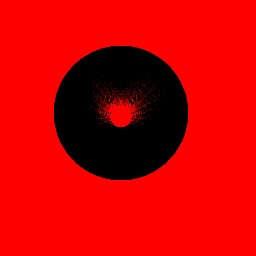
Due to the fact that our prepared buffer and texture are finite dimensions - on the calculated texture with caustic sampling error can occur, the image may appear to be a step and "is noisy" small points. It looks as follows:
To eliminate this effect, we need to filter out the texture of the caustic. For this we need an additional pass rendering to a texture. Draw in the texture, we will be one rectangle for the entire screen (fullscreen quad) with a shader, which will provide us with a small noise removal and smoothing texture. The basic idea of the filtering is to find the product of the current point and the sum of the neighboring pixels. If the points are around zero values - so that this point is the "noise" and, after multiplication by the sum of neighboring she will be filtered (as is zero). The shader is as follows:
  uniform sampler2D source_image; The At the entrance // <br> we have a caustic texture
 uniform vec2 the texel; // Size of one texel original texture

 in vec2 TexCoord;
 out vec4 FragColor;

 void main ()
  {
   vec2 dx = vec2 (texel.x, 0.0);
   vec2 dy = vec2 (0.0, texel.x);
   Make a selection // on the current texture coordinates of
   a float fCenter texture = (source_image, texCoord) .x;
   As well as // sample to the neighboring texels texture
   a float fNear texture = (source_image, texCoord - dx) .x + texture (source_image, texCoord + dx) .x +
	               texture (source_image, TexCoord - dy) .x + texture (source_image, TexCoord + dy) .x;
   // Divide by four and we square, then divide into two
   fNear = 0.03125 * fNear * fNear; // 0.5 * 0.25 * 0.25
   // Calculate the result of at least the original value and the new - for
   To this filter //, we did not raise the brightness of the image
   a float of value = min (fCenter, fNear * (fCenter + 1.0));
   FragColor = vec4 (value);
 }
The result of this shader is filtered image containing caustic:
6. Two premlomleniya with glass drawing
In the previous section, we figured out how to calculate the two refraction of light rays in the object. And let's think - is it possible to apply the same technique to improve the rendering of our object? Previously, we counted once refracted beam and did a sample of a cube map in that direction. This method is well suited for simulation of water - when the refracted beam then does not come out of their environment. But we are modeling a glass object that has a finite size. That is, to put it simply - if a ray of light fell into our facility, then sooner or later he has to get out of it. So I propose to calculate the actual point from which to make the transition glass-to-air and the direction in which it will move after the second refractive index. For this, we also need an additional pass - rendering the normal depth and rear edges of the object, but from the position of the observer.
Remember, in Section 2 we have found the direction vector view after the first refraction at the air-glass, and identified it as vRefracted?
Now we need to find the intersection of the beam at the rear edge of the object (the intersection of function we already have):
  vec3 vBackfaceIntersection = estimateIntersection (vVertexWS.xyz, vRefracted, mModelViewProjection,
                                                   mModelViewProjectionInverse, backface_depth);
 // We project it and read from the normal texture:
 vec4 vProjectedBI = mModelViewProjection * vec4 (vBackfaceIntersection, 1.0);
 vec3 vBackfaceNormal = vec3 (1.0) - 2.0 * texture (backface_texture, vec2 (0.5) +
                                                    0.5 * vProjectedBI.xy / vProjectedBI.w) .xyz;
 // Find the vector indicating the direction of the beam inside the object:
 vec3 vInnerRay = normalize (vBackfaceIntersection - vVertexWS.xyz);
... and here, too, should pause and explain something about the total internal reflection in this case.
The fact that the total internal reflection of the light beam from the object can exit at any other point (where the angle of incidence is less than the ratio of the refractive indices). But we use 2D texture with depth and normals and in general can not "see" the point at which the beam is reflected from the inner surface of the light will come from the object. So we make some assumption and assume that the reflected beam of light directly coming out of the object. Somehow the this a case with In Inappropriate to the get to do check on the vanishing of the of result of the function refract , SO <br> we'll take IT-source IT and modify a bit of fit to your Needs. Namely, in the case of total internal reflection will immediately return the reflected vector:
  vec3 computeRefractedVector (vec3 incidence, vec3 normal, a float eta)
  {
   float a etaIdotN = eta * Access dot (incidence, normal);
   float a the k = 1.0 - eta eta * + * etaIdotN etaIdotN;
   the if the (the the k <0.0)
       return statement statement The the Reflect (incidence, normal);
      else
     statement return eta incidence * - * normal (+ etaIdotN the sqrt (the k));
  }
Returning to the glass shader - and calculate the direction of the beam at the second refraction:
  vec3 vBackfaceRefracted = computeRefractedVector (vInnerRay, vBackfaceNormal.xyz
  , 1.0 / indexOfRefraction); // Now make a selection from the cubic texture in this direction:
 vec4 cBackfaceColor = texture (environment_map, vBackfaceRefracted);
 // And also mix it with the previously calculated based on the calculated reflection coefficient previously Fresnel:
 vec4 cColor = mix (cBackfaceColor, cReflection, fFresnel);
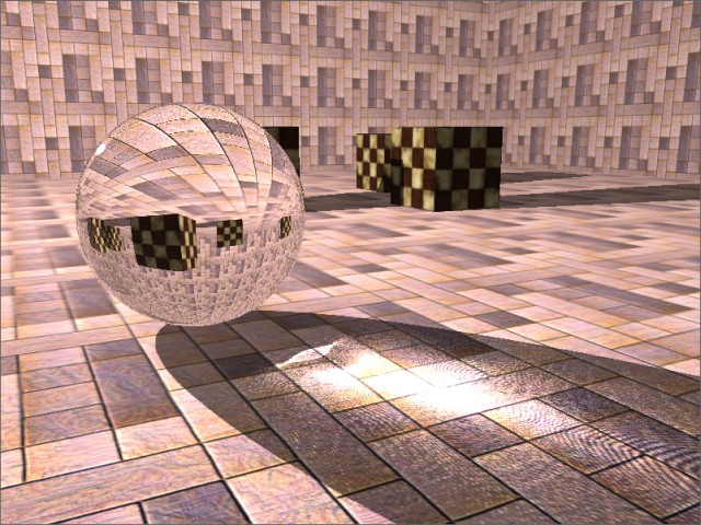
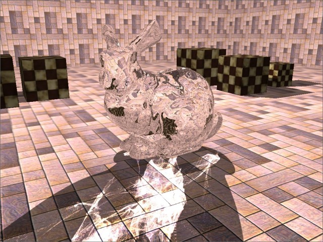
Well, that's all. Now we will have to get here is a picture:
7. Further development of the technology
As an additional "tokens" technique described can be incorporated into the calculations dispersion of light - a phenomenon in which the absolute index of refraction depends on the wavelength of light. That is, white light at the boundary of the material is split on the spectrum of each of the components which is deflected by different angles. Implementation of the method described in [2].
For the modeling of complex multiply surfaces where there is a "hole" (such as a torus), or to render caustics from several facilities located one behind the other must use the expansion stage in layers [7] as the two passes (with front and rear faces) will have enough.
8. Work program and source code
To the program Link, Showing the technique's Described: Glass_Rendering.zip
Program Management :
WASD has has - movement
of Left mouse button - the rotate the chamber
Tilda - display information (the FPS and the current settings)
The Settings :
"-" / "+" - Increase / Decrease glass refractive index (ranging from 1.01 to 2.5)
, "the the F1" - the enable / the disable the the HDR
"the the F2" - the enable / the disable the use of a geometry shaders
"the the F3 "- the enable / the disable the rendering of glass to two two refractions of rendering
" the F4 "- on / off rendering to two two refractions for caustic
Also, in the folder "config" file is named "appconfig", where you can customize the size of textures used and the model file that you want to display. The models are in the folder "data / models".
The Notes :
of The program may not work correctly with the ATI video cards. In particular geometry shaders do not work properly .
The source code is contained in the archive of the program, which is included in my engine. The project file in MS Visual Studio 2010 format.
useful links
Specification of the 1. the OpenGL
http://www.opengl.org/registry/
Of The caustic in 2. real time
http://www.gamedev.ru/code/articles/caustic
Implementation part of the Fast 3. lighting model the Cook-Torrance using the GLSL
http://www.gamedev.ru/code/articles/Cook-Torrance
The Mapping the Caustics 4 of Image of An .:-space Technique for the Real-time the the Caustics
http://graphics.cs.ucf.edu/caustics/
Fresnel Equations 5.
http://en.wikipedia.org/wiki/Fresnel_equations
Of The dispersion of 6. light
http://en.wikipedia.org/wiki/Dispersion_(optics)
Depth Peel or 7. decomposition scenes in layers
http://steps3d.narod.ru/tutorials/depth-peel-tutorial.html
源码下载地址:http://download.csdn.net/detail/u011417605/9814229
本文地址:http://blog.csdn.net/u011417605/article/details/70173928


 3972
3972


 被折叠的 条评论
为什么被折叠?
被折叠的 条评论
为什么被折叠?
 到【灌水乐园】发言


