


在ov5640芯片手册中看到这样一句话:
The OV5640 supports both a digital video parallel port and a serial MIPI port.
所以ov5640既支持数字并口视频传输,同样支持mipi接口规范。
摄像头插入到开发板上面的时候,如果有匹配的驱动程序,就会调用到probe函数,先从probe函数来分析。
(一)probe函数
1.1 获取设备ID
在probe函数中,首先通过几个of类函数来获取pwn-gpios,rst-gpios等的值。
然后就是设置sensor_data结构体ov5640_data。每个sensor_data结构体都代表一个具体的设备,来看看这个结构体:
struct sensor_data {
	const struct ov5642_platform_data *platform_data;
	struct v4l2_int_device *v4l2_int_device;
	struct i2c_client *i2c_client;
	struct v4l2_pix_format pix;
	struct v4l2_captureparm streamcap;
	bool on;  //设备是否上电

	/* control settings */
	int brightness;
	int hue;
	int contrast;
	int saturation;
	int red;
	int green;
	int blue;
	int ae_mode;

	u32 mclk;  //mclk时钟
	u8 mclk_source;  //mclk时钟源
	struct clk *sensor_clk;
	int csi;

	void (*io_init)(void);  //初始化函数
};然后就是填充这个结构体,重点是i2c_client的填充,需要根据填充的这个client来找到对应的设备。那么怎么确定找到的设备就是我们想要的呢?就是通过读设备的设备ID。可以看到在probe函数中通过:
retval= ov5640_read_reg(OV5640_CHIP_ID_HIGH_BYTE, &chip_id_high); 和
retval= ov5640_read_reg(OV5640_CHIP_ID_LOW_BYTE, &chip_id_low);
来分别读取ov5640设备ID的高字节和低字节。我们可以看到,在ov5640_mipi.c中是这样定义的:
#define OV5640_CHIP_ID_HIGH_BYTE	0x300A
#define OV5640_CHIP_ID_LOW_BYTE 0x300B我们将这两个地址去ov5640的芯片手册中搜索可以发现,

这两个地址就是ov5640设备的ID所在的地址,通过这个设备ID就能确定我们找到的设备。
1.2 ov5640_power_on函数
ov5640_power_on(dev);
ov5640_power_on(dev);
static int ov5640_power_on(struct device *dev)
{
	int ret = 0;

	io_regulator = devm_regulator_get(dev, "DOVDD");
	if (!IS_ERR(io_regulator)) {
		regulator_set_voltage(io_regulator,
				      OV5640_VOLTAGE_DIGITAL_IO,
				      OV5640_VOLTAGE_DIGITAL_IO);
		ret = regulator_enable(io_regulator);
		if (ret) {
			pr_err("%s:io set voltage error\n", __func__);
			return ret;
		} else {
			dev_dbg(dev,
				"%s:io set voltage ok\n", __func__);
		}
	} else {
		pr_err("%s: cannot get io voltage error\n", __func__);
		io_regulator = NULL;
	}

	core_regulator = devm_regulator_get(dev, "DVDD");
	if (!IS_ERR(core_regulator)) {
		regulator_set_voltage(core_regulator,
				      OV5640_VOLTAGE_DIGITAL_CORE,
				      OV5640_VOLTAGE_DIGITAL_CORE);
		ret = regulator_enable(core_regulator);
		if (ret) {
			pr_err("%s:core set voltage error\n", __func__);
			return ret;
		} else {
			dev_dbg(dev,
				"%s:core set voltage ok\n", __func__);
		}
	} else {
		core_regulator = NULL;
		pr_err("%s: cannot get core voltage error\n", __func__);
	}

	analog_regulator = devm_regulator_get(dev, "AVDD");
	if (!IS_ERR(analog_regulator)) {
		regulator_set_voltage(analog_regulator,
				      OV5640_VOLTAGE_ANALOG,
				      OV5640_VOLTAGE_ANALOG);
		ret = regulator_enable(analog_regulator);
		if (ret) {
			pr_err("%s:analog set voltage error\n",
				__func__);
			return ret;
		} else {
			dev_dbg(dev,
				"%s:analog set voltage ok\n", __func__);
		}
	} else {
		analog_regulator = NULL;
		pr_err("%s: cannot get analog voltage error\n", __func__);
	}

	return ret;
}从上面的程序中可以看出来,它设置了三个regulator,中文翻译为”稳定器“,内核中有关于这个的模块的驱动框架,关于这个驱动框架的分析可以查看:
http://www.wowotech.net/pm_subsystem/regulator_framework_overview.html
我们这里只分析与我们相关的东西。
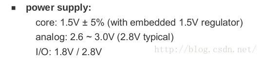
通过regulator_set_voltage函数来为这几个regulator设置电压,分别设置为OV5640_VOLTAGE_DIGITAL_IO,OV5640_VOLTAGE_DIGITAL_CORE和OV5640_VOLTAGE_ANALOG。
#define OV5640_VOLTAGE_ANALOG               2800000
#define OV5640_VOLTAGE_DIGITAL_CORE         1500000
#define OV5640_VOLTAGE_DIGITAL_IO 1800000同时,在dts文件中,定义了它的电压为多少,
	ov564x_mipi: ov564x_mipi@3c { /* i2c2 driver */
		compatible = "ovti,ov564x_mipi";
		reg = <0x3c>;
		clocks = <&clks 201>;
		clock-names = "csi_mclk";
		<span style="color:#FF0000;">DOVDD-supply = <&vgen4_reg>; /* 1.8v */
		AVDD-supply = <&vgen3_reg>;  /* 2.8v, rev C board is VGEN3
						rev B board is VGEN5 */
		DVDD-supply = <&vgen2_reg>;  /* 1.5v*/ </span>
		pwn-gpios = <&gpio1 19 1>;   /* active low: SD1_CLK */
		rst-gpios = <&gpio1 20 0>;   /* active high: SD1_DAT2 */
		csi_id = <1>;
		mclk = <24000000>;
		mclk_source = <0>;
};可以看出来,它们设置的一致。那么在dts文件中为啥这么设置呢?肯定是根据ov5640的芯片手册中设置的:
1.3 ov5640_reset函数
ov5640_reset();这个函数用来重置摄像头,如下所示:
static void ov5640_reset(void)
{
	/* camera reset */
	gpio_set_value(rst_gpio, 1);

	/* camera power dowmn */
	gpio_set_value(pwn_gpio, 1);
	msleep(5);

	gpio_set_value(pwn_gpio, 0);
	msleep(5);

	gpio_set_value(rst_gpio, 0);
	msleep(1);

	gpio_set_value(rst_gpio, 1);
	msleep(5);

	gpio_set_value(pwn_gpio, 1);
}这里面的rst_gpio和pwn_gpio是在probe函数中通过of类函数获取的,既然是通过of类函数获得的,那么在dts文件中肯定有对应的设置:
	ov564x_mipi: ov564x_mipi@3c { /* i2c2 driver */
		compatible = "ovti,ov564x_mipi";
		reg = <0x3c>;
		clocks = <&clks 201>;
		clock-names = "csi_mclk";
		DOVDD-supply = <&vgen4_reg>; /* 1.8v */
		AVDD-supply = <&vgen3_reg>;  /* 2.8v, rev C board is VGEN3
						rev B board is VGEN5 */
		DVDD-supply = <&vgen2_reg>;  /* 1.5v*/
		<span style="color:#FF0000;">pwn-gpios = <&gpio1 19 1>;   /* active low: SD1_CLK */
		rst-gpios = <&gpio1 20 0>;   /* active high: SD1_DAT2 */ </span>
		csi_id = <1>;
		mclk = <24000000>;
		mclk_source = <0>;
};这个函数操作的是gpio1的19和20位,关于这两位引脚的意义还需要继续深入。它一共包含3个参数,第一个参数表示gpio1,第二个参数是否表示gpio1的哪一位??第三个参数表示默认值。比如说pwn-gpios的默认值是1,说明置0的时候是上电,置1的时候是关电。
同时,重置摄像头的时候,ov5640_reset()函数设置pwn-gpios和rst-gpios的写入顺序是否是固定的?
1.3 ov5640_standby函数
ov5640_standby(0);
static void ov5640_standby(s32 enable)
{
	if (enable)
		gpio_set_value(pwn_gpio, 1);
	else
		gpio_set_value(pwn_gpio, 0);
	msleep(2);
}这个函数就是根据函数的传入参数来向pwn_gpio寄存器写值,向pwn_gpio寄存器写1表示关电,写0代表关电。至于向寄存器中写1代表上电还是关电,这个需要查看对应寄存器在dts文件中写进去的值。
1.4
先上电,通过ov5640_read_reg函数来获取摄像头的设备ID以后,再次使用ov5640_standby(1);来关电。
之后就是通过ov5640_int_device.priv= &ov5640_data;来将ov5640_int_device结构体的priv指向设置好的sensor_data结构体,然后通过
retval= v4l2_int_device_register(&ov5640_int_device);来将ov5640_int_device作为一个slave设备注册到v4l2框架中,在这个函数中,会将slave设备添加到int_list链表中,尝试使用v4l2_int_device_try_attach_all函数来匹配master设备。
(二)在probe函数执行完毕以后,就可以操作这个摄像头了,之后我们继续按照mxc_v4l2_capture.c这个应用程序的执行过程来完善ov5640_mipi的一些操作。首先是open函数。
2.1 vidioc_int_g_ifparm函数
在open函数中,首先调用vidioc_int_g_ifparm(cam->sensor,&ifparm);函数来从slave设备中获取ifparm的信息,最终会调用到ov5640_mipi.c的ioctl_g_ifparm函数。先来看open函数中,它传入了两个参数:cam->sensor,ifparm;其实在ov5640_mipi.c中,它并没有从cam->sensor里面获取ifparm的信息来填充到ifparm中,而是在ioctl_g_ifparm函数中直接为ifparm中的各个成员变量赋值。主要是为ifparm.u.bt656成员赋值,包括clock_curr,mode,clock_min,clock_max等等。
2.2 vidioc_int_g_fmt_cap函数
在这个函数中,就直接用f->fmt.pix= sensor->pix;来将sensor_data里面的pix结构体赋给了cam_fmt里面的fmt.pix结构体。
2.3 vidioc_int_s_power函数
vidioc_int_s_power(cam->sensor, 1);

static int ioctl_s_power(struct v4l2_int_device *s, int on)
{
	struct sensor_data *sensor = s->priv;
	if (on && !sensor->on) {
		if (io_regulator)
			if (regulator_enable(io_regulator) != 0)
				return -EIO;
		if (core_regulator)
			if (regulator_enable(core_regulator) != 0)
				return -EIO;
		if (gpo_regulator)
			if (regulator_enable(gpo_regulator) != 0)
				return -EIO;
		if (analog_regulator)
			if (regulator_enable(analog_regulator) != 0)
				return -EIO;
		/* Make sure power on */
		ov5640_standby(0);
	} else if (!on && sensor->on) {
		if (analog_regulator)
			regulator_disable(analog_regulator);
		if (core_regulator)
			regulator_disable(core_regulator);
		if (io_regulator)
			regulator_disable(io_regulator);
		if (gpo_regulator)
			regulator_disable(gpo_regulator);
		ov5640_standby(1);
	}
	sensor->on = on;
	return 0;
}在这个函数中,会根据vidioc_int_s_power函数传入的第二个参数的值on来决定是否将设备上电。1表示上电,0表示关电。这里面的io_regulator,core_regulator和analog_regulator是在ov5640_power_on函数中获取到的,gpo_regulator应该没有设置。然后需要注意的一点是:在ioctl_s_power函数中的第二个参数如果为1的话代表上电,为0的话代表关电。但是在ov5640_standby函数中,如果为0代表上电,为1代表关电。所以,在if(on &&!sensor->on)判断语句中,如果想要确定摄像头是上电的话,需要使用ov5640_standby(0);。这一点比较拗口。
2.4 vidioc_int_dev_init函数
vidioc_int_dev_init(cam->sensor);

static int ioctl_dev_init(struct v4l2_int_device *s)
{
	struct sensor_data *sensor = s->priv;
	u32 tgt_xclk;	/* target xclk */
	u32 tgt_fps;	/* target frames per secound */
	int ret;
	enum ov5640_frame_rate frame_rate;
	void *mipi_csi2_info;

	ov5640_data.on = true;

	/* mclk */
	tgt_xclk = ov5640_data.mclk;
	tgt_xclk = min(tgt_xclk, (u32)OV5640_XCLK_MAX);
	tgt_xclk = max(tgt_xclk, (u32)OV5640_XCLK_MIN);
	ov5640_data.mclk = tgt_xclk;

	pr_debug("   Setting mclk to %d MHz\n", tgt_xclk / 1000000);

	/* Default camera frame rate is set in probe */
	tgt_fps = sensor->streamcap.timeperframe.denominator /
		  sensor->streamcap.timeperframe.numerator;

	pr_debug(" tft_fps is %d.\n", tgt_fps);

	if (tgt_fps == 15)
		frame_rate = ov5640_15_fps;
	else if (tgt_fps == 30)
		frame_rate = ov5640_30_fps;
	else
		return -EINVAL; /* Only support 15fps or 30fps now. */

	mipi_csi2_info = mipi_csi2_get_info();

	/* enable mipi csi2 */
	if (mipi_csi2_info)
		mipi_csi2_enable(mipi_csi2_info);
	else {
		printk(KERN_ERR "%s() in %s: Fail to get mipi_csi2_info!\n",
		       __func__, __FILE__);
		return -EPERM;
	}

	ret = ov5640_init_mode(frame_rate, ov5640_mode_INIT, ov5640_mode_INIT);

	return ret;
}
2.4.1
在这个函数中,首先通过tgt_xclk= ov5640_data.mclk;来获取到mclk的值。这个ov5640_data.mclk是在probe函数中设置的。然后对tgt_xclk与摄像头允许的最大值最小值进行判断,
#define OV5640_XCLK_MIN 6000000
#define OV5640_XCLK_MAX 24000000使得tgt_xclk位于这个区间内。
然后计算tgt_fps的值,它需要的两个值同样是在probe函数中设置的。
根据tgt_fps的值来设置frame_rate的值,这个frame_rate用在后面的ov5640_init_mode函数中。
然后通过mipi_csi2_get_info函数来获取到mxc_mipi_csi2.c文件中的gmipi_csi2结构体,这个结构体是一个全局变量。获取到这个结构体以后通过mipi_csi2_enable函数来使能。具体操作是设置mipi_csi2_info结构体里面的mipi_en位为true,然后通过clk_prepare_enable函数来使能mipi_csi2_info结构体里面的cfg_clk和dphy_clk。
之后就是调用ov5640_init_mode函数了。
2.4.2 ov5640_init_mode函数
这个函数在ioctl_s_parm函数和ioctl_dev_init函数中调用,这个函数用来设置ov5640的模式,有以下几种模式:
enum ov5640_mode {
	ov5640_mode_MIN = 0,
	ov5640_mode_VGA_640_480 = 0,
	ov5640_mode_QVGA_320_240 = 1,
	ov5640_mode_NTSC_720_480 = 2,
	ov5640_mode_PAL_720_576 = 3,
	ov5640_mode_720P_1280_720 = 4,
	ov5640_mode_1080P_1920_1080 = 5,
	ov5640_mode_QSXGA_2592_1944 = 6,
	ov5640_mode_QCIF_176_144 = 7,
	ov5640_mode_XGA_1024_768 = 8,
	ov5640_mode_MAX = 8,
	ov5640_mode_INIT = 0xff, /*only for sensor init*/
};在mxc_v4l2_capture.c这个应用程序中,可以通过-m选项来指定使用哪种模式,然后将-m后面指定的模式保存在g_capture_mode中,然后通过parm.parm.capture.capturemode= g_capture_mode;再调用ioctl(fd_v4l,VIDIOC_S_PARM, &parm)函数,最终就会调用这个ov5640_init_mode函数来修改ov5640的模式。
在ioctl_dev_init函数中已经设置了frame_rate,然后设置ov5640_init_mode函数其他两个参数,第二个参数表示新设置的mode,第三个参数表示原来的mode。但是需要注意的是在mxc_v4l2_capture.c中的mxc_v4l_open函数,它调用ov5640_init_mode来初始化摄像头,这时候,摄像头的初始mode和新mode都没有指定,上面说了,它们是在VIDIOC_S_PARMioctl中指定的,这时候就需要指定ov5640_init_mode的第二个和第三个参数都为ov5640_mode_INIT。
static int ov5640_init_mode(enum ov5640_frame_rate frame_rate,
			    enum ov5640_mode mode, enum ov5640_mode orig_mode)
{
	struct reg_value *pModeSetting = NULL;
	s32 ArySize = 0;
	int retval = 0;
	void *mipi_csi2_info;
	u32 mipi_reg, msec_wait4stable = 0;
	enum ov5640_downsize_mode dn_mode, orig_dn_mode;

	if ((mode > ov5640_mode_MAX || mode < ov5640_mode_MIN)
		&& (mode != ov5640_mode_INIT)) {
		pr_err("Wrong ov5640 mode detected!\n");
		return -1;
} /*对mode进行判断,根据上面列举的enumov5640_mode,它就是判断传入的mode是否合法。*/
	mipi_csi2_info = mipi_csi2_get_info(); //获取 mipi_csi2_info

	/* initial mipi dphy */
	if (!mipi_csi2_info) {
		printk(KERN_ERR "%s() in %s: Fail to get mipi_csi2_info!\n",
		       __func__, __FILE__);
		return -1;
} /*判断mipi_csi2_info是否获取成功*/
	if (!mipi_csi2_get_status(mipi_csi2_info))
		mipi_csi2_enable(mipi_csi2_info);

	if (!mipi_csi2_get_status(mipi_csi2_info)) {
		pr_err("Can not enable mipi csi2 driver!\n");
		return -1;
} /*首先判断mipi_csi2_info中mipi_en是否置位,这一位表示是否使能了mipi摄像头。如果没有使能的话,就调用mipi_csi2_enable函数来使能mipi_csi2_info里面的cfg_clk和dphy_clk,然后将mipi_en置位为true。设置好以后继续调用mipi_csi2_get_status函数来确定是否使能成功。*/
mipi_csi2_set_lanes(mipi_csi2_info); /*在这个函数中将mipi_csi2_info里面的lanes的值写到MIPI_CSI2_N_LANES寄存器中,
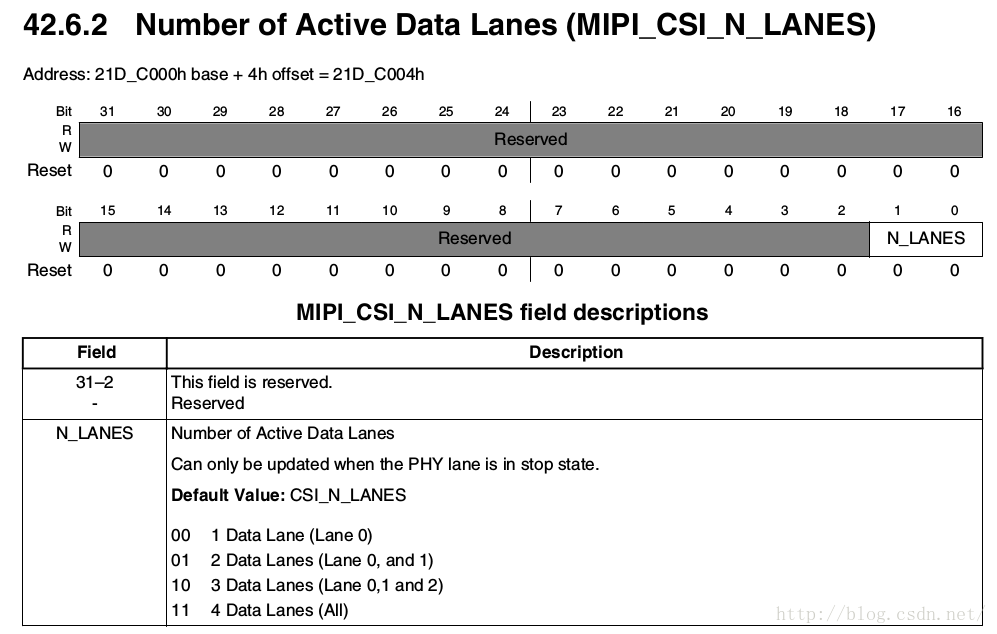
而这个mipi_csi2_info里面的lanes的值是什么时候获取到的呢?在mxc_mipi_csi2.c文件中的mipi_csi2_probe函数中,通过of_property_read_u32函数来保存到mipi_csi2_info中的。
*/
	/*Only reset MIPI CSI2 HW at sensor initialize*/
	if (mode == ov5640_mode_INIT)
		mipi_csi2_reset(mipi_csi2_info);
/*如果是mode等于ov5640_mode_INIT,就表示是在ioctl_dev_init函数中调用的,就调用mipi_csi2_reset函数来初始化MIPI_CSI2相关的寄存器。这个函数在mxc_mipi_csi2.c文件中定义.
int mipi_csi2_reset(struct mipi_csi2_info *info)
{
	_mipi_csi2_lock(info);

	mipi_csi2_write(info, 0x0, MIPI_CSI2_PHY_SHUTDOWNZ);
	mipi_csi2_write(info, 0x0, MIPI_CSI2_DPHY_RSTZ);
	mipi_csi2_write(info, 0x0, MIPI_CSI2_CSI2_RESETN);

	mipi_csi2_write(info, 0x00000001, MIPI_CSI2_PHY_TST_CTRL0);
	mipi_csi2_write(info, 0x00000000, MIPI_CSI2_PHY_TST_CTRL1);
	mipi_csi2_write(info, 0x00000000, MIPI_CSI2_PHY_TST_CTRL0);
	mipi_csi2_write(info, 0x00000002, MIPI_CSI2_PHY_TST_CTRL0);
	mipi_csi2_write(info, 0x00010044, MIPI_CSI2_PHY_TST_CTRL1);
	mipi_csi2_write(info, 0x00000000, MIPI_CSI2_PHY_TST_CTRL0);
	mipi_csi2_write(info, 0x00000014, MIPI_CSI2_PHY_TST_CTRL1);
	mipi_csi2_write(info, 0x00000002, MIPI_CSI2_PHY_TST_CTRL0);
	mipi_csi2_write(info, 0x00000000, MIPI_CSI2_PHY_TST_CTRL0);

	mipi_csi2_write(info, 0xffffffff, MIPI_CSI2_PHY_SHUTDOWNZ);
	mipi_csi2_write(info, 0xffffffff, MIPI_CSI2_DPHY_RSTZ);
	mipi_csi2_write(info, 0xffffffff, MIPI_CSI2_CSI2_RESETN);

	_mipi_csi2_unlock(info);

	return 0;
}
EXPORT_SYMBOL(mipi_csi2_reset);这个函数中反复向MIPI_CSI2_PHY_TST_CTRL0和MIPI_CSI2_PHY_TST_CTRL1寄存器中写不同的值,到底有什么目的??明天来了把值写进去仔细看看。*/
	if (ov5640_data.pix.pixelformat == V4L2_PIX_FMT_UYVY)
		mipi_csi2_set_datatype(mipi_csi2_info, MIPI_DT_YUV422);
	else if (ov5640_data.pix.pixelformat == V4L2_PIX_FMT_RGB565)
		mipi_csi2_set_datatype(mipi_csi2_info, MIPI_DT_RGB565);
	else
pr_err("currently this sensor format can not be supported!\n"); /*根据ov5640_data.pix.pixelformat的值来设置mipi_csi2_info里面的datatype的值。通过mipi_csi2_set_datatype函数来设置。这个ov5640_data.pix.pixelformat的值是在ov5640_probe函数中设置的。从这两个判断语句中可以推断出来,在这个驱动中,指定摄像头只支持V4L2_PIX_FMT_UYVY和V4L2_PIX_FMT_RGB565两种格式。*/
/*看下面的代码前,需要对enumov5640_downsize_mode进行一个初步的了解:
/* image size under 1280 * 960 are SUBSAMPLING
 * image size upper 1280 * 960 are SCALING
 */
enum ov5640_downsize_mode {
	SUBSAMPLING,
	SCALING,
};这个enum的注释写的很清楚了,当imagesize大于1280* 960时,downsize_mode为SCALING,当imagesize小于1280* 960时,downsize_mode为SUBSAMPLING。下面的代码主要是根据新mode的ov5640_downsize_mode类型和初始mode的ov5640_downsize_mode类型来决定使用哪个函数来切换mode模式。*/
	dn_mode = ov5640_mode_info_data[frame_rate][mode].dn_mode;
orig_dn_mode = ov5640_mode_info_data[frame_rate][orig_mode].dn_mode; /*在这里有一个二维数组ov5640_mode_info_data:
staticstruct ov5640_mode_info ov5640_mode_info_data[2][ov5640_mode_MAX +1],再来看这个函数中,它会根据frame_rate和mode两个下标来找到对应的元素。关于这个frame_rate,它是enumov5640_frame_rate类型的,
enum ov5640_frame_rate {
	ov5640_15_fps,
	ov5640_30_fps
};这两个值默认为0和1.关于enum的默认值的分析可以看:《C语言enum枚举类型解析》
http://blog.csdn.net/skyflying2012/article/details/22736633
*/
	if (mode == ov5640_mode_INIT) {
		pModeSetting = ov5640_init_setting_30fps_VGA;
		ArySize = ARRAY_SIZE(ov5640_init_setting_30fps_VGA);

		ov5640_data.pix.width = 640;
		ov5640_data.pix.height = 480;
		retval = ov5640_download_firmware(pModeSetting, ArySize);
		if (retval < 0)
			goto err;

		pModeSetting = ov5640_setting_30fps_VGA_640_480;
		ArySize = ARRAY_SIZE(ov5640_setting_30fps_VGA_640_480);
		retval = ov5640_download_firmware(pModeSetting, ArySize);
} /*当mode为ov5640_mode_INIT时,代表第一次初始化摄像头设备,就直接设置pModeSetting和ArySize的值,然后调用ov5640_download_firmware函数来初始化摄像头。在这个文件中,可以看出来ov5640_init_setting_30fps_VGA数组是一堆寄存器的地址和值的组合,通过这个函数来设置摄像头内部寄存器的值,而不是设置开发板上面的控制寄存器。这些值可以对照ov5640摄像头的芯片手册来查看。但是不理解的是,在这里设置了两次,分别为ov5640_init_setting_30fps_VGA和ov5640_setting_30fps_VGA_640_480。*/
else if ((dn_mode == SUBSAMPLING && orig_dn_mode == SCALING) ||
			(dn_mode == SCALING && orig_dn_mode == SUBSAMPLING)) {
		/* change between subsampling and scaling
		 * go through exposure calucation */
		retval = ov5640_change_mode_exposure_calc(frame_rate, mode);
} /*因为dn_mode和orig_dn_mode都是enumov5640_downsize_mode类型的,它们都只有两种值,所以当两者不同时,就通过ov5640_change_mode_exposure_calc函数来改变摄像头的mode。*/
else {
		/* change inside subsampling or scaling
		 * download firmware directly */
		retval = ov5640_change_mode_direct(frame_rate, mode);
} /*当dn_mode和orig_dn_mode这两者相同时,就直接调用ov5640_change_mode_direct函数改变mode就行了。关于这三个函数的分析,在分析完这个函数后分析。*/
	if (retval < 0)
goto err; /*总之,当调用ov5640_init_mode函数的时候,比如在ioctl_dev_init函数中调用,它就表示第一次使用摄像头,ov5640_init_mode函数的mode模式都为ov5640_mode_INIT,然后就会在ov5640_init_mode函数中调用ov5640_download_firmware函数来设置摄像头上面的寄存器。如果是在VIDIOC_S_PARMioctl调用的时候,这时候,就可能修改ov5640_init_mode函数里面的mode模式,这时候就需要根据mode模式里面的ov5640_downsize_mode来判断是否改变了,如果改变了的话,就会调用ov5640_change_mode_exposure_calc函数来设置摄像头上面的寄存器,如果没有改变的话,就直接调用ov5640_change_mode_direct设置摄像头上面的寄存器即可。*/
OV5640_set_AE_target(AE_Target); /*关于这一块的讲解查看ov5640芯片手册的《4.5AEC/AGC algorithms》这一节,主要是设置自动曝光控制(AutoExposure Control,AEC)和自动增益控制(AutoGain Control,AGC)。
函数如下所示:
static int OV5640_set_AE_target(int target)
{
/* stable in high */
int fast_high, fast_low;
AE_low = target * 23 / 25; /* 0.92 */
AE_high = target * 27 / 25; /* 1.08 */
fast_high = AE_high<<1;
if (fast_high > 255)
fast_high = 255;
fast_low = AE_low >> 1;
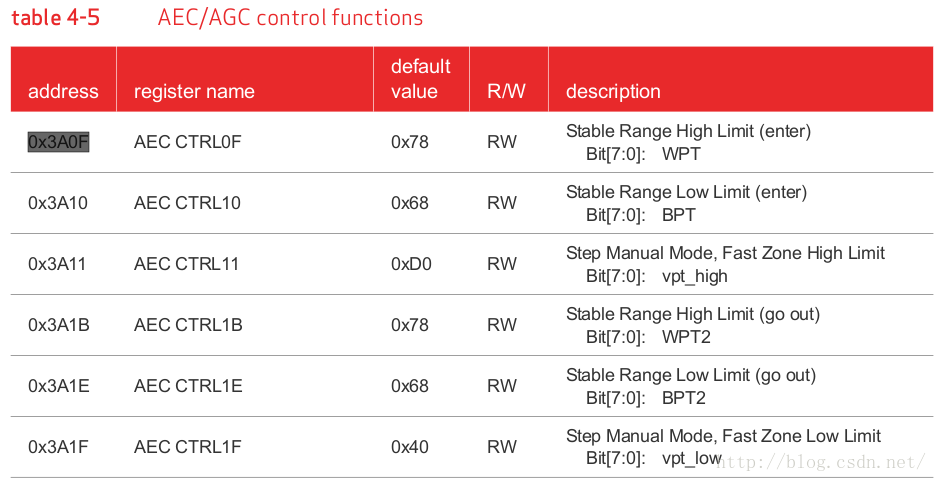
ov5640_write_reg(0x3a0f, AE_high);
ov5640_write_reg(0x3a10, AE_low);
ov5640_write_reg(0x3a1b, AE_high);
ov5640_write_reg(0x3a1e, AE_low);
ov5640_write_reg(0x3a11, fast_high);
ov5640_write_reg(0x3a1f, fast_low);
return 0;
}这个计算过程是摄像头相关的算法,在芯片手册中详细介绍了。
ov5640芯片上面的0x3a0f存储的是曝光时间的最大值,0x3a10存储的是曝光时间的最小值。通过这个函数可以看出来它的计算过程。
0x3a1b存储的是图像从稳定状态切换到不稳定状态时曝光时间的最大值,0x3a1e存储的是图像从稳定状态切换到不稳定状态时曝光时间的最小值。
这时候需要理解另外一个寄存器:0x56a1,这个寄存器中保存的是目标图像的亮度平均值,这个寄存器是一个只读寄存器。

当0x56a1寄存器的值不在{0x3a1e,0x3a1b}这个区间之内时,AEC就调整它们,并且使他们位于{0x3a10,0x3a0f}这个区间。所以这个{0x3a1e,0x3a1b}这个区间称为稳定状态区间。
当0x56a1寄存器的值位于{0x3a1e,0x3a1b}这个区间的时候,就是指图像处于稳定状态。反之,则称为不稳定状态。
上面的讲解是AEC处于auto状态时,AEC就会去自动调节这些参数,同时,这个AEC支持manual模式,关于这个模式的选择,是通过操作0x3503寄存器来完成的,我们在后面的OV5640_turn_on_AE_AG()函数分析中再具体分析。
当AEC处于manual模式的时候,还分为normal和fast选择。normal就是支持手工一点一点地调节曝光量,fast快速的调节曝光量。究竟有多快速呢。。。{0x3a1f,0x3a11}这个区间是fast情况下的曝光区间,当0x56a1寄存器里面的值小于0x3a1f时,AEC就直接将0x56a1寄存器里面的值乘2;当0x56a1寄存器里面的值大于0x3a11时,AEC就直接将0x56a1寄存器里面的值除以2。
*/
OV5640_get_light_freq(); /*这个函数如下所示,这个函数的目的是获得ov5640的频闪,关于摄像头频闪的讲解,可以查看《Camera图像处理原理分析-抗噪变焦 频闪 等 》
http://blog.csdn.net/colorant/article/details/1913334:
static int OV5640_get_light_freq(void)
{
	/* get banding filter value */
	int temp, temp1, light_freq = 0;
	u8 tmp;

	temp = ov5640_read_reg(0x3c01, &tmp);

	if (temp & 0x80) {
		/* manual */
		temp1 = ov5640_read_reg(0x3c00, &tmp);
		if (temp1 & 0x04) {
			/* 50Hz */
			light_freq = 50;
		} else {
			/* 60Hz */
			light_freq = 60;
		}
	} else {
		/* auto */
		temp1 = ov5640_read_reg(0x3c0c, &tmp);
		if (temp1 & 0x01) {
			/* 50Hz */
			light_freq = 50;
		} else {
			/* 60Hz */
/* 这里是不是一个bug,应该写上:light_freq = 60; */
		}
	}
	return light_freq;
}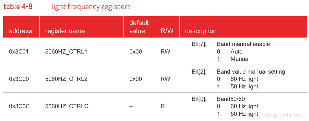
对比程序和芯片手册,可以看出来,首先会根据0x3c01的bit[7]来判断是auto还是manual模式,
如果为auto模式的话,就会去读取0x3c0c寄存器的bit[0],为1的话就是50Hz的频闪,为0的话就是60Hz的频闪。
如果为manual模式的话,就会去读取0x3c00寄存器的bit[2],为1的话就是50Hz的频闪,为0的话就是60Hz的频闪。
*/
OV5640_set_bandingfilter(); /*这个函数是设置摄像头的工频干扰,CMOS是行曝光,也就是在每行曝光时间决定了画面的亮度,举例:一个50HZ的光源,电压曲线为正弦曲线,那能量曲线定性分析可以认为是取了绝对值的电压曲线。那就是能量做1/100秒的周期变化。那就要求曝光的时间必须是1/100秒的整数倍。如果没有把曝光时间调整到1/100秒的整数倍,就有可能会有每行的曝光值不一样,造成同一个image上有水波纹现象。CCD是整帧同时曝光,所以,工频干扰表现的就是图像有轻微的闪烁。产生的原理与CMOS sensor的原理相似。
static void OV5640_set_bandingfilter(void)
{
	int prev_VTS;
	int band_step60, max_band60, band_step50, max_band50;

	/* read preview PCLK */
	prev_sysclk = OV5640_get_sysclk();
	/* read preview HTS */
	prev_HTS = OV5640_get_HTS();

	/* read preview VTS */
	prev_VTS = OV5640_get_VTS();

	/* calculate banding filter */
	/* 60Hz */
	band_step60 = prev_sysclk * 100/prev_HTS * 100/120;
	ov5640_write_reg(0x3a0a, (band_step60 >> 8));
	ov5640_write_reg(0x3a0b, (band_step60 & 0xff));

	max_band60 = (int)((prev_VTS-4)/band_step60);
	ov5640_write_reg(0x3a0d, max_band60);

	/* 50Hz */
	band_step50 = prev_sysclk * 100/prev_HTS;
	ov5640_write_reg(0x3a08, (band_step50 >> 8));
	ov5640_write_reg(0x3a09, (band_step50 & 0xff));

	max_band50 = (int)((prev_VTS-4)/band_step50);
	ov5640_write_reg(0x3a0e, max_band50);
} 关于这个函数,它首先通过OV5640_get_sysclk函数来获取系统的时钟,然后OV5640_get_HTS和OV5640_get_VTS函数分别获取ov5640的Horizontaltotalsize 和verticaltotal size,对于50Hz和60Hz,有不同的计算方式,但是这个计算方法看半天都没有理解。。。
*/
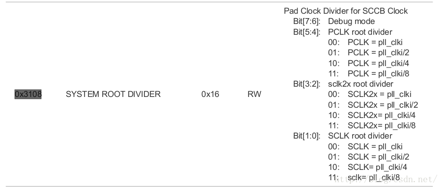
ov5640_set_virtual_channel(ov5640_data.csi); /*这个函数设置虚拟通道,如下所示:
static void ov5640_set_virtual_channel(int channel)
{
	u8 channel_id;

	ov5640_read_reg(0x4814, &channel_id);
	channel_id &= ~(3 << 6);
	ov5640_write_reg(0x4814, channel_id | (channel << 6));
}但是在ov5640的芯片手册中,这几位显示的是DEBUGMODE,如下所示

*/
	/* add delay to wait for sensor stable */
	if (mode == ov5640_mode_QSXGA_2592_1944) {
		/* dump the first two frames: 1/7.5*2
		 * the frame rate of QSXGA is 7.5fps */
		msec_wait4stable = 267;
	} else if (frame_rate == ov5640_15_fps) {
		/* dump the first nine frames: 1/15*9 */
		msec_wait4stable = 600;
	} else if (frame_rate == ov5640_30_fps) {
		/* dump the first nine frames: 1/30*9 */
		msec_wait4stable = 300;
	}
msleep(msec_wait4stable); /*根据不同的模式来选择等待sensor稳定的时间。*/
	if (mipi_csi2_info) {
		unsigned int i;

		i = 0;

		/* wait for mipi sensor ready */
		mipi_reg = mipi_csi2_dphy_status(mipi_csi2_info);
		while ((mipi_reg == 0x200) && (i < 10)) {
			mipi_reg = mipi_csi2_dphy_status(mipi_csi2_info);
			i++;
			msleep(10);
		}

		if (i >= 10) {
			pr_err("mipi csi2 can not receive sensor clk!\n");
			return -1;
		}
/* mipi_csi2_dphy_status函数就是去读取MIPI_CSI2_PHY_STATE寄存器的值,然后保存在mipi_reg变量中。这个寄存器如下所示:
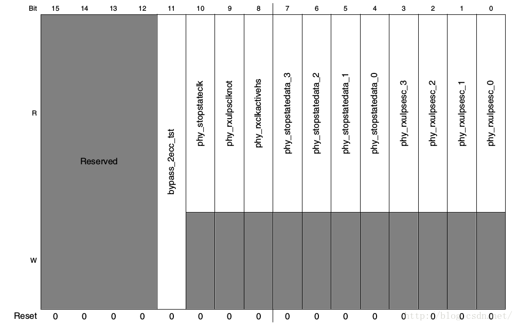

可以看出来,这个寄存器的bit[9]表示sensor的clocklane处于什么样的状态。注意:这一位是activelow,所以置0时表示使能。再来看这一段代码,它会一直等待这一位置0,一直等待10×10ms,如果过了这一段时间,MIPI_CSI2_PHY_STATE寄存器的bit[9]还保持为1的状态时,就打印出“mipicsi2 can not receive sensor clk!”这句话报错。
*/
		i = 0;

		/* wait for mipi stable */
		mipi_reg = mipi_csi2_get_error1(mipi_csi2_info);
		while ((mipi_reg != 0x0) && (i < 10)) {
			mipi_reg = mipi_csi2_get_error1(mipi_csi2_info);
			i++;
			msleep(10);
		}

		if (i >= 10) {
			pr_err("mipi csi2 can not reveive data correctly!\n");
			return -1;
		}
	}
err:
	return retval;
}/*这一段代码就是通过mipi_csi2_get_error1函数来读取MIPI_CSI2_ERR1寄存器的值。这个寄存器表示MIPI控制寄存器中是否有错误发生,如果都没有错误的话,这个寄存器里面的值都应该是0.关于这个寄存器中每一位的含义就不分析了。*/
至此,ov5640_init_mode函数就大致分析完毕了,也就代表ioctl_dev_init函数分析完毕。这个ioctl_dev_init函数是mxc_v4l2_open函数中的最后一个函数。
对于应用程序中调用的其他ioctl函数,大致过程都是相似的,不会涉及到芯片上面寄存器的设置,大部分都是与ov5640_probe函数中sensor_data结构体相关,就不再分析他们了。
下面分析ov5640_init_mode函数中没有分析的三个函数:
ov5640_download_firmware
ov5640_change_mode_exposure_calc
ov5640_change_mode_direct这三个函数是关于芯片设置最重要的函数。在ov5640_init_mode函数中,会根据第二个参数和第三个参数的不同来选择执行哪一路过程。当mode== ov5640_mode_INIT时,会直接执行ov5640_download_firmware函数来设置ov5640摄像头。
先来看ov5640_download_firmware函数:
/* download ov5640 settings to sensor through i2c */
static int ov5640_download_firmware(struct reg_value *pModeSetting, s32 ArySize)
{
	register u32 Delay_ms = 0;
	register u16 RegAddr = 0;
	register u8 Mask = 0;
	register u8 Val = 0;
	u8 RegVal = 0;
	int i, retval = 0;

	for (i = 0; i < ArySize; ++i, ++pModeSetting) {
		Delay_ms = pModeSetting->u32Delay_ms;
		RegAddr = pModeSetting->u16RegAddr;
		Val = pModeSetting->u8Val;
		Mask = pModeSetting->u8Mask;

		if (Mask) {
			retval = ov5640_read_reg(RegAddr, &RegVal);
			if (retval < 0)
				goto err;

			RegVal &= ~(u8)Mask;
			Val &= Mask;
			Val |= RegVal;
		}

		retval = ov5640_write_reg(RegAddr, Val);
		if (retval < 0)
			goto err;

		if (Delay_ms)
			msleep(Delay_ms);
	}
err:
	return retval;
}先看这个函数的注释:通过I2C总线下载设置到ov5640摄像头中。意思就是我们在驱动中写好ov5640摄像头上面寄存器的配置以后,通过这个函数设置进去。
再来看这个函数,这个函数设置的核心是reg_value结构体,这个结构体如下所示:
struct reg_value {
	u16 u16RegAddr;
	u8 u8Val;
	u8 u8Mask;
	u32 u32Delay_ms;
};它就包含了所要设置一个寄存器所需要的所有元素:地址,值,掩码,延迟时间。以ov5640_init_setting_30fps_VGA[]为例:
static struct reg_value ov5640_init_setting_30fps_VGA[] = {
	{0x3103, 0x11, 0, 0}, {0x3008, 0x82, 0, 5}, {0x3008, 0x42, 0, 0},
	{0x3103, 0x03, 0, 0}, {0x3017, 0x00, 0, 0}, {0x3018, 0x00, 0, 0},
	{0x3034, 0x18, 0, 0}, {0x3035, 0x14, 0, 0}, {0x3036, 0x38, 0, 0},
。。。。。。。。。。。。。。。。。。
};通过这个函数,就能够把这个结构体数组里面的值都设置到ov5640中去。而这个结构体数组中寄存器的值怎么来的就是关键了,理论上可以参考芯片手册一位一位地设置,但是厂家应该会提供这个初始化数组的。
下面来看第二个函数ov5640_change_mode_exposure_calc:
/* sensor changes between scaling and subsampling
 * go through exposure calcualtion
 */
static int ov5640_change_mode_exposure_calc(enum ov5640_frame_rate frame_rate,
				enum ov5640_mode mode)
{
	struct reg_value *pModeSetting = NULL;
	s32 ArySize = 0;
	u8 average;
	int prev_shutter, prev_gain16;
	int cap_shutter, cap_gain16;
	int cap_sysclk, cap_HTS, cap_VTS;
	int light_freq, cap_bandfilt, cap_maxband;
	long cap_gain16_shutter;
	int retval = 0;

	/* check if the input mode and frame rate is valid */
	pModeSetting =
		ov5640_mode_info_data[frame_rate][mode].init_data_ptr;
	ArySize =
		ov5640_mode_info_data[frame_rate][mode].init_data_size;

	ov5640_data.pix.width =
		ov5640_mode_info_data[frame_rate][mode].width;
	ov5640_data.pix.height =
		ov5640_mode_info_data[frame_rate][mode].height;

	if (ov5640_data.pix.width == 0 || ov5640_data.pix.height == 0 ||
		pModeSetting == NULL || ArySize == 0)
		return -EINVAL;

	/* auto focus */
	/* OV5640_auto_focus();//if no af function, just skip it */

	/* turn off AE/AG */
OV5640_turn_on_AE_AG(0); /*这个函数的意思是根据传入的参数的值来决定打开还是关闭autoAE/AG。关于这个的寄存器地址是0x3503,可以看出来,想要关闭auto模式的话,只需要将bit[1:0]设置为0x03即可,打开auto的话,将bit[1:0]清空即可。OV5640_turn_on_AE_AG这个函数正是这么做的。
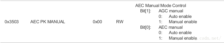
static void OV5640_turn_on_AE_AG(int enable)
{
	u8 ae_ag_ctrl;

	ov5640_read_reg(0x3503, &ae_ag_ctrl);
	if (enable) {
		/* turn on auto AE/AG */
		ae_ag_ctrl = ae_ag_ctrl & ~(0x03);
	} else {
		/* turn off AE/AG */
		ae_ag_ctrl = ae_ag_ctrl | 0x03;
	}
	ov5640_write_reg(0x3503, ae_ag_ctrl);
}
*/
/* read preview shutter */
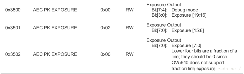
prev_shutter = OV5640_get_shutter();
if ((binning_on()) && (mode != ov5640_mode_720P_1280_720)
&& (mode != ov5640_mode_1080P_1920_1080))
prev_shutter *= 2; /*这个OV5640_get_shutter()函数就是去读取ov5640芯片上面的0x3500~0x3502地址里面的值,然后根据图示构造出Exposure的值,返回保存到prev_shutter中。在这里,shutter就是曝光时间的意思。
在这里有一个函数:binning_on():
static bool binning_on(void)
{
	u8 temp;
	ov5640_read_reg(0x3821, &temp);
	temp &= 0xfe;
	if (temp)
		return true;
	else
		return false;
}关于binning的概念和理解,可以查看《sensor的skippingand binning 模式》
http://blog.csdn.net/sloan6/article/details/8242713
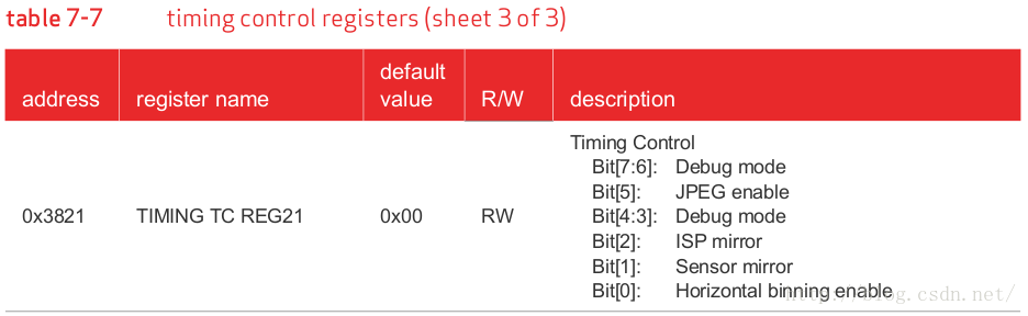
在ov5640的芯片手册中,可以看到,与这个概念有关的寄存器位于0x3821的bit[0],但是个人感觉这个函数写的有问题,只涉及0x3821的bit[0]位,如果只打算比较bit[0]而不改变其他位的话,应该:
if(temp & 0x01),根本不需要temp&= 0xfe操作,经过这一个操作的话,假如其他位有不为0的,那么这个temp的值就不为0.
*/
	/* read preview gain */
prev_gain16 = OV5640_get_gain16(); /*看看OV5640_get_gain16()这个函数:
static int OV5640_get_gain16(void)
{
	 /* read gain, 16 = 1x */
	int gain16;
	u8 temp;

	gain16 = ov5640_read_reg(0x350a, &temp) & 0x03;
	gain16 = (gain16<<8) + ov5640_read_reg(0x350b, &temp);

	return gain16;
}从这个函数中很显然就能猜出来这个previewgain保存在0x350a和0x350b这两个寄存器中,看看芯片手册:
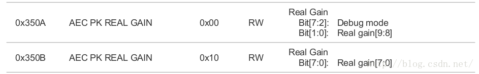
最终这个函数读取这两个寄存器的值,然后保存在prev_gain16变量中。
*/
	/* get average */
ov5640_read_reg(0x56a1, &average); /*这里直接使用ov5640_read_reg函数来读取0x56a1的值保存在&average中:
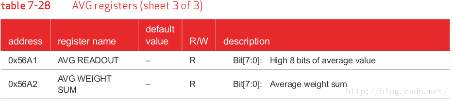
*/
	/* turn off night mode for capture */
OV5640_set_night_mode(); /*这个函数如下所示,这个函数与上面的binning_on()函数做比较的话,这个函数的设置是正确的,因为这个函数只想设置0x3a00的bit[2]为0,在不改变其他位的基础上面,通过mode&= 0xfb的形式是最好的。
static void OV5640_set_night_mode(void)
{
	 /* read HTS from register settings */
	u8 mode;

	ov5640_read_reg(0x3a00, &mode);
	mode &= 0xfb;
	ov5640_write_reg(0x3a00, mode);
}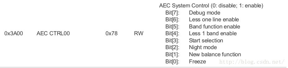
*/
	/* turn off overlay */
	/* ov5640_write_reg(0x3022, 0x06);//if no af function, just skip it */

	OV5640_stream_off();

	/* Write capture setting */
	retval = ov5640_download_firmware(pModeSetting, ArySize);
	if (retval < 0)
goto err; /*最终这个函数里面也是调用ov5640_download_firmware函数来将从ov5640_mode_info_data数组中获取到的ov5640中寄存器的值写到对应的寄存器中。*/
	/* read capture VTS */
	cap_VTS = OV5640_get_VTS();
	cap_HTS = OV5640_get_HTS();
cap_sysclk = OV5640_get_sysclk(); /*先来看前两个函数,读取寄存器的值来获取verticalzise和horizontalsize的值。寄存器如下所示:
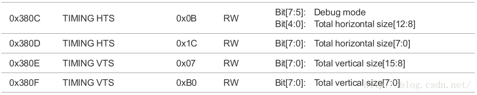
这个OV5640_get_sysclk()函数有点复杂,以后再分析。
*/
	/* calculate capture banding filter */
	light_freq = OV5640_get_light_freq();
	if (light_freq == 60) {
		/* 60Hz */
		cap_bandfilt = cap_sysclk * 100 / cap_HTS * 100 / 120;
	} else {
		/* 50Hz */
		cap_bandfilt = cap_sysclk * 100 / cap_HTS;
	}
	cap_maxband = (int)((cap_VTS - 4)/cap_bandfilt);

	/* calculate capture shutter/gain16 */
	if (average > AE_low && average < AE_high) {
		/* in stable range */
		cap_gain16_shutter =
		  prev_gain16 * prev_shutter * cap_sysclk/prev_sysclk
		  * prev_HTS/cap_HTS * AE_Target / average;
	} else {
		cap_gain16_shutter =
		  prev_gain16 * prev_shutter * cap_sysclk/prev_sysclk
		  * prev_HTS/cap_HTS;
	}

	/* gain to shutter */
	if (cap_gain16_shutter < (cap_bandfilt * 16)) {
		/* shutter < 1/100 */
		cap_shutter = cap_gain16_shutter/16;
		if (cap_shutter < 1)
			cap_shutter = 1;

		cap_gain16 = cap_gain16_shutter/cap_shutter;
		if (cap_gain16 < 16)
			cap_gain16 = 16;
	} else {
		if (cap_gain16_shutter >
				(cap_bandfilt * cap_maxband * 16)) {
			/* exposure reach max */
			cap_shutter = cap_bandfilt * cap_maxband;
			cap_gain16 = cap_gain16_shutter / cap_shutter;
		} else {
			/* 1/100 < (cap_shutter = n/100) =< max */
			cap_shutter =
			  ((int) (cap_gain16_shutter/16 / cap_bandfilt))
			  *cap_bandfilt;
			cap_gain16 = cap_gain16_shutter / cap_shutter;
		}
	}

	/* write capture gain */
	OV5640_set_gain16(cap_gain16);

	/* write capture shutter */
	if (cap_shutter > (cap_VTS - 4)) {
		cap_VTS = cap_shutter + 4;
		OV5640_set_VTS(cap_VTS);
	}
	OV5640_set_shutter(cap_shutter);

	OV5640_stream_on();

err:
	return retval;
}/*后面这些计算应该都是摄像头中定义的,有点看不懂,以后再分析吧*/
最后看看ov5640_change_mode_direct函数:
static int ov5640_change_mode_direct(enum ov5640_frame_rate frame_rate,
				enum ov5640_mode mode)
{
	struct reg_value *pModeSetting = NULL;
	s32 ArySize = 0;
	int retval = 0;

	/* check if the input mode and frame rate is valid */
	pModeSetting =
		ov5640_mode_info_data[frame_rate][mode].init_data_ptr;
	ArySize =
		ov5640_mode_info_data[frame_rate][mode].init_data_size;

	ov5640_data.pix.width =
		ov5640_mode_info_data[frame_rate][mode].width;
	ov5640_data.pix.height =
		ov5640_mode_info_data[frame_rate][mode].height;

	if (ov5640_data.pix.width == 0 || ov5640_data.pix.height == 0 ||
		pModeSetting == NULL || ArySize == 0)
		return -EINVAL;

	/* turn off AE/AG */
	OV5640_turn_on_AE_AG(0);

	OV5640_stream_off();

	/* Write capture setting */
	retval = ov5640_download_firmware(pModeSetting, ArySize);
	if (retval < 0)
		goto err;

	OV5640_stream_on();

	OV5640_turn_on_AE_AG(1);

err:
	return retval;
}
经过上一个函数的分析,这个函数看起来就相当简单了。
3.OV5640_get_sysclk 函数分析
static int OV5640_get_sysclk(void)
{
	 /* calculate sysclk */
	int xvclk = ov5640_data.mclk / 10000;
	int temp1, temp2;
	int Multiplier, PreDiv, VCO, SysDiv, Pll_rdiv;
	int Bit_div2x = 1, sclk_rdiv, sysclk;
u8 temp; /*ov5640_data.mclk的值是在ov5640_probe函数中同dts文件中读取的,为24000000.*/
int sclk_rdiv_map[] = {1, 2, 4, 8};
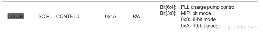
temp1 = ov5640_read_reg(0x3034, &temp);
temp2 = temp1 & 0x0f;
if (temp2 == 8 || temp2 == 10)
Bit_div2x = temp2 / 2; /*读取0x3034寄存器的值,取低4位除以2后保存在Bit_div2x中。从芯片手册中可以看出来,0x3034的低4位是MIPIbit mode,那么为什么还要除以2呢?在《ov5640_PLL_diagram.jpg》图片的左下角有这样一句话:note6:MIPISCLK= (4 or 5) * PCLK if 2 lanes;= (8 or 10) * PCLK if 1lane。再看Bit_div2x在PLLdiagram中对应的模块是BITdivider,而现在使用的是2lanes模式,所以需要除以2.
*/
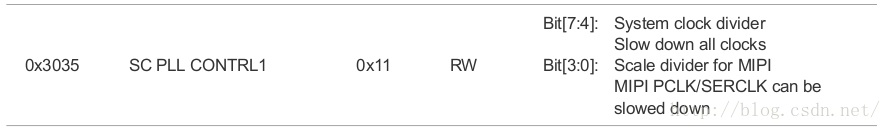
	temp1 = ov5640_read_reg(0x3035, &temp);
	SysDiv = temp1>>4;
	if (SysDiv == 0)
SysDiv = 16; /*读取0x3035寄存器的高4位保存在SysDiv中,看芯片手册中的解释是系统时钟分频器。在《ov5640_PLL_diagram.jpg》图片中对应SYSdivider0模块。
*/
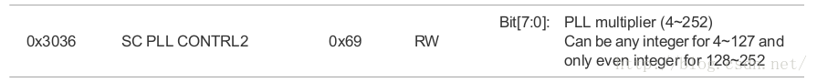
	temp1 = ov5640_read_reg(0x3036, &temp);
Multiplier = temp1; /*读取0x3036寄存器的值保存在Multiplier中,看芯片手册中的解释是PLL倍频器。在《ov5640_PLL_diagram.jpg》图片中对应multiplier模块。
*/
	temp1 = ov5640_read_reg(0x3037, &temp);
	PreDiv = temp1 & 0x0f;
Pll_rdiv = ((temp1 >> 4) & 0x01) + 1; /*读取0x3037寄存器的低4位保存在PreDiv中,读取0x3037寄存器的bit[4]保存在Pll_rdiv中。
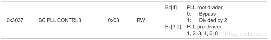
PreDiv在《ov5640_PLL_diagram.jpg》图片中对应pre-divider模块,Pll_rdiv在《ov5640_PLL_diagram.jpg》图片中对应PLLR divider模块,因为上图中的解释是:如果bit[4]为1的话,就分成2份,所以在代码中将从bit[4]中读取出来的值加1。*/
	temp1 = ov5640_read_reg(0x3108, &temp);
	temp2 = temp1 & 0x03;
sclk_rdiv = sclk_rdiv_map[temp2]; /*读取0x3108寄存器的低2位保存在temp2中,然后将这个temp2作为下标来从这个数组里面取值:
intsclk_rdiv_map[] = {1, 2, 4, 8};
为什么要从这个数组里面取值呢?看芯片手册中,SCLK为pll_clk的1/2,1/4, 1/8。没法用两位来表示8,所以选择这种方式来选取值。
*/
VCO = xvclk * Multiplier / PreDiv; /*这个VCO是压控振荡器(VoltageControlledOscillator),是PLL(锁相环)的组成部分,在PLL中,一般是先分频,然后再经过VCO增频,这里先计算的是VCO的输出。在《ov5640_PLL_diagram.jpg》中就是PLL1后的输出。*/
sysclk = VCO / SysDiv / Pll_rdiv * 2 / Bit_div2x / sclk_rdiv; /*剩下的就是计算过程,根据图《ov5640_PLL_diagram.jpg》就可以写出这个计算过程。*/
	return sysclk;
}《ov5640_PLL_diagram.jpg》是我们网上看到的一个有关ov5640的时钟控制图,我下载的芯片手册都没有这个图,所以一直对这个函数不理解,通过这个图,这个函数的设置过程就很清楚了,《ov5640_PLL_diagram.jpg》图片如下所示:
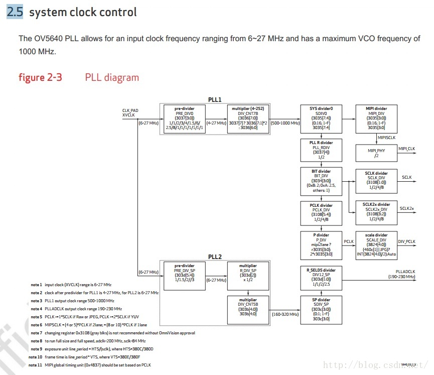
经过上面的步骤就可以得出OV5640的系统时钟参数。
参考:
http://blog.csdn.net/yapingmcu/article/details/37817727


 1万+
1万+


 被折叠的 条评论
为什么被折叠?
被折叠的 条评论
为什么被折叠?
 到【灌水乐园】发言


