


From: http://assafmuller.com/2013/
In the last post we gave context – How are GRE tunnels used outside of the virtualization world.
In this post we’ll examine how GRE tunnels are an alternative to VLANs as an OpenStack Neutron
cloud networking configuration. GRE tunnels like VLANs have two main roles:
To provide connectivity between all VMs in a tenant network, regardless of which compute node the VMs reside in
To segregate VMs in different tenant networks
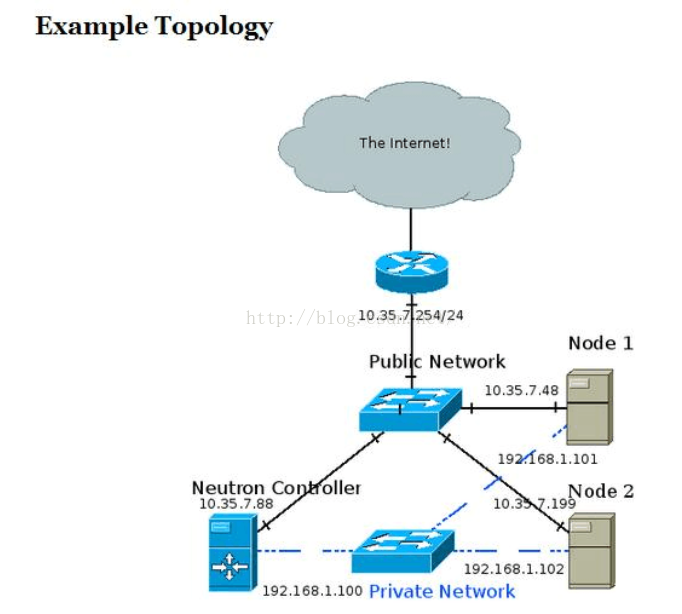
Example Topology
Topology Neutron GRE
The recommended deployment topology is more complicated and can involve an API, management,
data and external network.
In my test setup the Neutron controller is also a compute node, and all three nodes are connected
to a private network through which the GRE tunnels are created and VM traffic is forwarded.
Management traffic also goes through the private network.
The public network is eventually connected to the internet and is also how I SSH into the different
machines from my development station.
I achieved the topology using oVirt to provision three VMs across two physical hosts.
The two hosts are physically connected to a public network and to each other.
The three VMs are ran on a RHEL 6.5 beta release with kernel that supports ip namespaces (For example: 2.6.32-130).
I used Packstack to install OpenStack Havana which installed the correct version of Open vSwitch (1.11) that supports GRE tunneling.
High Level View
Whenever a layer 2 agent (Open vSwitch) goes up it uses OpenStack’s messaging queue to
notify the Neutron controller that it’s up. A GRE tunnel is then formed between the node and the controller,
and the controller notifies the other nodes that a new node has joined the party.
A GRE tunnel is then formed between the new node and every pre-existing node.
In other words,a full mesh is formed between the controller and all compute nodes,
and the tunnel ID header field in the GRE header is used to differentiate between different tenant networks.
The GRE tunnels encapsulate Ethernet frames leaving the VMs and thus create a giant broadcast domain
per tenant network, spanning over all compute nodes.
Medium Level View
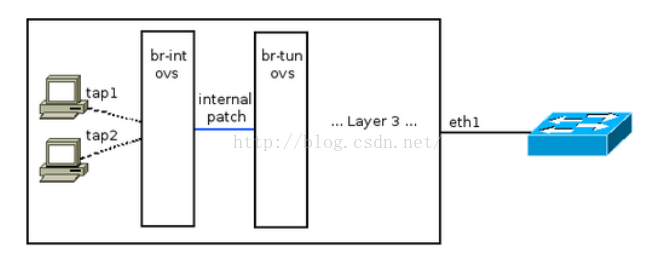
VMs are connected as usual via tap devices to an Open vSwitch bridge called br-int.
This is actually a simplification which will be expanded upon later in this post.
br-int is connected via an internal OVS patch port to another bridge called br-tun.
This internal patch port is similar to a veth pair: A Linux networking device pair where if a
packet is sent down one end it will magically appear at the other end.
Such a device is created via:
ip link add veth0 type veth peer name veth1
The ovs internal patch port however is not registered as a normal networking device.
It is not visible with “ip address” or “ifconfig”. The important bit is that both br-int and
br-tun view it as a normal switch port.
If you are unfamiliar with Open vSwitch flow tables you might want to consider stopping
by a previous post: Open vSwitch Basics.
br-int, in a GRE configuration, works as a normal layer 2 learning switch. We can confirm this by looking at its flow table:[root@NextGen1 ~]# ovs-ofctl dump-flows br-int NXST_FLOW reply (xid=0x4):
cookie=0x0, duration=176865.121s, table=0, n_packets=64757, n_bytes=13893740,
idle_age=13, hard_age=65534, priority=1 actions=NORMAL
We can see that br-int is in “normal” mode.
The interesting part is then: What’s going on with br-tun?
[root@NextGen1 ~]# ovs-vsctl show 911ff1ca-590a-4efd-a066-568fbac8c6fb
[... Bridge br-int omitted ...]
Bridge br-tun
Port patch-int
Interface patch-int
type: patch
options: {peer=patch-tun}
Port br-tun
Interface br-tun
type: internal
Port "gre-2"
Interface "gre-2"
type: gre
options: {in_key=flow, local_ip="192.168.1.100", out_key=flow, remote_ip="192.168.1.101"}
Port "gre-1"
Interface "gre-1"
type: gre
options: {in_key=flow, local_ip="192.168.1.100", out_key=flow, remote_ip="192.168.1.102"}
We can see that an interface called “patch-int” connects br-tun to br-int.
More important are the two GRE interfaces – Both with a tunnel source IP of 192.168.1.100
(The controller machine in the topology above), but with different tunnel remote IPs: 101 and 102.
When the two local VMs want to communicate with one another br-tun is out of the picture.
The messages reach br-int, which acts as a normal layer 2 learning switch and acts accordingly.
But, when a VM wants to communicate with a VM on another compute node,
or when it needs to send a broadcast or multicast message then things get interesting and br-tun comes into play.
In our example, let’s assume a tenant network 10.0.0.0/8 exists.
10.0.0.1 will be a VM on the Neutron controller (Remember in my test lab it’s also a compute node)
and VM 10.0.0.2 will reside on “Node 1″. When 10.0.0.1 pings 10.0.0.2 the following flow occurs:
VM1 pings VM2. Before VM1 can create an ICMP echo request message,
VM1 must send out an ARP request for VM2′s MAC address.
A quick reminder about ARP encapsulation – It is encapsulated directly in an Ethernet frame – No IP involved
(There exists a base assumption that states that ARP requests never leave a broadcast domain therefor
IP packets are not needed). The Ethernet frame leaves VM1′s tap device into the host’s br-int. br-int,
acting as a normal switch, sees that the destination MAC address in the Ethernet frame is FF:FF:FF:FF:FF:FF –
The broadcast address. Because of that it floods it out all ports, including the patch cable linked to br-tun.
br-tun receives the frame from the patch cable port and sees that the destination MAC address is the broadcast address.
Because of that it will send the message out all GRE tunnels (Essentially flooding the message).
But before that, it will encapsulate the message in a GRE header and an IP packet. In fact,
two new packets are created: One from 192.168.1.100 to 192.168.1.101,
and the other from 192.168.1.100 to 192.168.1.102. The encapsulation over the GRE tunnels looks like this:
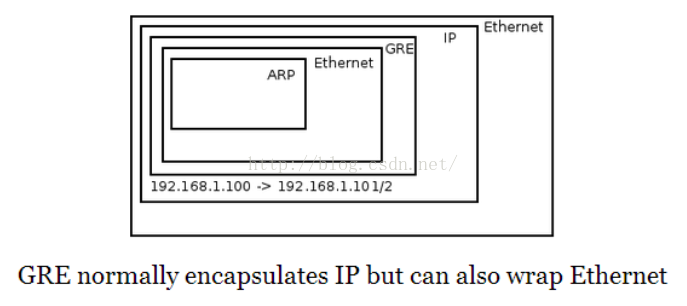
Each tenant network is mapped to a GRE tunnel ID which is written in the GRE header.
Both compute nodes get the message. Node 1 in particular receives the message, sees that it is destined to his own IP address.
The outer IP header has “GRE” as the “Next Protocol” field. In the GRE header the tunnel ID is written and
because it is correctly configured and matches Node 1′s local configuration the message is not dropped,
but the IP and GRE headers are discarded. The Ethernet frame is forwarded to br-int which floods it to all VMs.
VM 2 receives the message and responds to the ARP request with his own MAC address.
The reverse process then occurs and VM1 gets his answer, at which point it can initiate an ICMP echo request directly to VM 2.
For unicast traffic we really want to avoid flooding the message out to all GRE tunnels.
Ideally we’d want to forward the message only to the host where the VM resides in.
This is accomplished by learning MAC addresses on incoming traffic from GRE tunnels in to br-int.
Infact, earlier when the ARP reply came back from the GRE tunnel into the compute node VM 1 resides in,
a new flow was inserted into br-tun’s flow table. The new flow matches against the tenant’s network tunnel ID,
with a destination MAC address of VM2, and the flow’s action is to forward it to the GRE tunnel that reaches VM 2′s compute node.
To summarize, we can conclude that the flow logic on br-tun implements a learning switch
but with a GRE twist. If the message is to a multicast, broadcast, or unknown unicast address
it is forwarded out all GRE tunnels. Otherwise if it learned the destination MAC address via earlier messages
(By observing the source MAC address, tunnel ID and incoming GRE port) then it forwards it to the correct GRE tunnel.
Low Level View
[root@NextGen1 ~]# ovs-ofctl dump-flows br-tun NXST_FLOW reply (xid=0x4):
cookie=0x0, duration=182369.287s, table=0, n_packets=5996, n_bytes=1481720,
idle_age=52, hard_age=65534, priority=1,in_port=3 actions=resubmit(,2)
cookie=0x0, duration=182374.574s, table=0, n_packets=14172, n_bytes=3908726,
idle_age=5, hard_age=65534, priority=1,in_port=1 actions=resubmit(,1)
cookie=0x0, duration=182370.094s, table=0, n_packets=0, n_bytes=0,
idle_age=65534, hard_age=65534, priority=1,in_port=2 actions=resubmit(,2)
cookie=0x0, duration=182374.078s, table=0, n_packets=3, n_bytes=230,
idle_age=65534, hard_age=65534, priority=0 actions=drop
cookie=0x0, duration=182373.435s, table=1, n_packets=3917, n_bytes=797884,
idle_age=52, hard_age=65534, priority=0,dl_dst=00:00:00:00:00:00/01:00:00:00:00:00
actions=resubmit(,20) cookie=0x0, duration=182372.888s, table=1, n_packets=10255, n_bytes=3110842, idle_age=5, hard_age=65534, priority=0,dl_dst=01:00:00:00:00:00/01:00:00:00:00:00 actions=resubmit(,21)
cookie=0x0, duration=182103.664s, table=2, n_packets=5982, n_bytes=1479916,
idle_age=52, hard_age=65534, priority=1,tun_id=0x1388 actions=mod_vlan_vid:1,resubmit(,10)
cookie=0x0, duration=182372.476s, table=2, n_packets=14, n_bytes=1804,
idle_age=65534, hard_age=65534, priority=0 actions=drop
cookie=0x0, duration=182372.099s, table=3, n_packets=0, n_bytes=0,
idle_age=65534, hard_age=65534, priority=0 actions=drop
cookie=0x0, duration=182371.777s, table=10, n_packets=5982, n_bytes=1479916,
idle_age=52, hard_age=65534, priority=1 actions=learn(table=20,hard_timeout=300,
priority=1,NXM_OF_VLAN_TCI[0..11],NXM_OF_ETH_DST[]=NXM_OF_ETH_SRC[],load:0->NXM_OF_VLAN_TCI[],load:NXM_NX_TUN_ID[]->NXM_NX_TUN_ID[],output:NXM_OF_IN_PORT[]),output:1
cookie=0x0, duration=116255.067s, table=20, n_packets=3917, n_bytes=797884, hard_timeout=300,
idle_age=52, hard_age=52, priority=1,vlan_tci=0x0001/0x0fff,dl_dst=fa:16:3e:1f:19:55
actions=load:0->NXM_OF_VLAN_TCI[],load:0x1388->NXM_NX_TUN_ID[],output:3 cookie=0x0, duration=182371.623s, table=20, n_packets=0, n_bytes=0, idle_age=65534, hard_age=65534, priority=0 actions=resubmit(,21)
cookie=0x0, duration=182103.777s, table=21, n_packets=10235, n_bytes=3109310,
idle_age=5, hard_age=65534, priority=1,dl_vlan=1 actions=strip_vlan,set_tunnel:0x1388,output:3,output:2
cookie=0x0, duration=182371.507s, table=21, n_packets=20, n_bytes=1532, idle_age=65534, hard_age=65534, priority=0 actions=drop
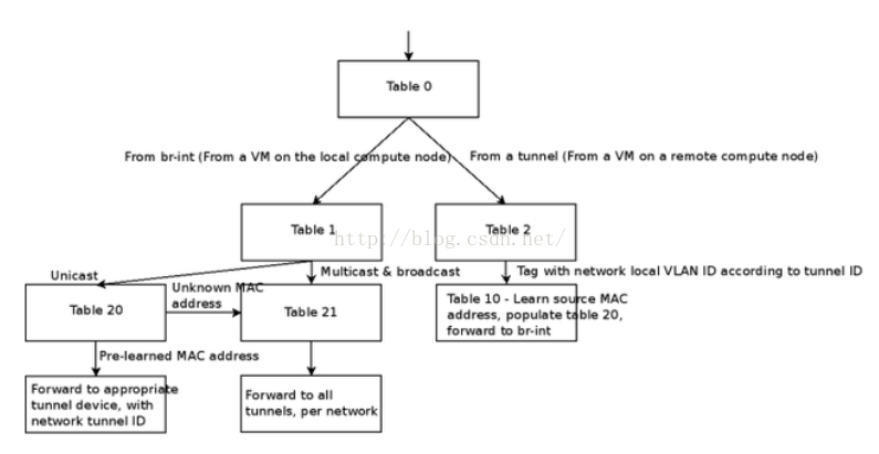
Outgoing Traffic
Table 0 has 4 flows. The last one is a default drop flow. br-tun has two GRE tunnels,
one to NextGen2 and one to NextGen3, connected to ports 2 and 3.
We can see that if the message came from a GRE tunnel it is resubmitted to table 2.
br-int is connected via an internal patch port to port1. Any message coming in from a VM
will come in from br-int and will be resubitted to table 1.
Table 1 gets any message that originated from VMs via br-int. If the destination MAC address
if a unicast address, it is resubmitted to table 20, otherwise it is resubmitted to table 21.
The unicast OR (multicast | broadcast) check is done by observing the 8th bit of the MAC address.
All multicast addresses, as well as the broadcast address (FF:FF:FF:FF:FF:FF) have 1 in that slot.
Another way to put it – If the 8th bit (Going left to right) is on, then it is NOT a unicast address.
Table 20 gets any unicast VM traffic. This table is populated via learning by observing
traffic coming in from the GRE tunnels – We’ll go over this in a bit. If the destination MAC address
is known it is forwarded to the appropriate GRE tunnel, otherwise the message is resubmitted to table 21.
Table 21 gets multicast and broadcast traffic as well as traffic destined to unknown MAC addresses. You’ll notice that the first flow in table 21 matches against vlan 1. The vlan is stripped,
GRE tunnel ID 0×1388 (5000 in decimal) is loaded and the message is sent out all GRE tunnels.
The br-tun flow table doesn’t actually tag any frames, and br-int’s flow table is empty / in normal mode,
so where are these tagged frames coming from? If you run ovs-vsctl show,
you’ll see that br-int’s ports are VLAN access ports.
Every tenant network is provisioned a locallysignificant VLAN tag.
The ports are vlan tagged by flow tables, but by simply adding the port as a VLAN access port
(ovs-vsctl add-port br-int tap0 tag=1). Any traffic coming in from tap0 will be tagged by vlan 1,
and any traffic going to tap0 will be stripped of the vlan tag.
Incoming Traffic
Observing table 0 we can see that traffic coming in from GRE tunnels is resubmitted to table 2.
In Table 2 we can see that tunnel ID 0×1388 traffic is resubmitted to table 10 right after being tagged with vlan 1.
Table 10 is where the interesting bit happens. It has a single flow that matches any message.
It has a “learn” action that creates a new flow and places it in table 20 – Unicast traffic coming in fromVMs.
The new flow’s destination MAC address match is the current frame’s source MAC address,
and the out port is the current frame’s in port. Finally, the message itself is forwarded to br-int.
Segregation
So far we talked about how GRE tunnels implement VM connectivity. Like VLANs,
GRE tunnels need to provide segregation between tenant networks both within a
compute node and across compute nodes.Within a compute node we’ll recall that br-int adds
VM taps as VLAN access ports. This means that VMs that are connected to the same tenant
network get the same VLAN tag.Across compute nodes we use the GRE tunnel ID.
As discussed previously, each tenant network is provisioned both a GRE tunnel ID and a locally significant VLAN tag.
That means that incoming traffic with a GRE tunnel ID is converted to the correct local VLAN tag as can be seen in table 2.
The message is then forwarded to br-int already VLAN tagged and the appropriate check can be made.


 9600
9600


 被折叠的 条评论
为什么被折叠?
被折叠的 条评论
为什么被折叠?
 到【灌水乐园】发言


