


1. 疑问
使用u-boot开发一些项目有一段时间了,对u-boot也更加熟悉了。以前经常想u-boot存在的意义到底是啥呢?百科上说U-Boot的作用是系统引导。恩?引导系统?具体什么含义?u-boot在实际开发中还有什么具体作用?好吧,如果你对这些问题感兴趣,是吧。………………
2. u-boot在实际项目中的作用
以我的项目经历,我觉着u-boot有如下3种功能:
一,验证硬件是否正常工作。
二,提供简单的固件开发、调试方法。
三,引导OS。
下面一个一个说说:
一,验证硬件是否正常工作。新设计的硬件原理,PCB制版和焊接完成。高高兴兴地从车间拿来,先搞电、复位、时钟。这些都是一些电气信号,好不好可以通过示波器测量。然后呐,你很想验证自己设计的这套原理的正确性,板子上的各个部件都能正常工作吗?比如说CPU能执行程序吗?内存好用吗?串口好用吗?网口好用吗?PCIE好用吗?等等好多部件你都很想让其本本分分地工作,为人类服务。这个时候就得“软件”上了。板子上最核心的部件是CPU,这个玩意可以执行所谓的指令,也就是说你可以命令它帮你干活。好家伙,这个听起来我好喜欢,不过就是命令这个家伙有点费劲。因为他听不懂普通话,连English也完全不懂。它懂ASM、C、C++、Java、Php、Python、Perl等等语言。哦,有点扯远了,我的主要意思是这货既然可以按照你的意愿去干活,那我们就可以利用它来验证我们板子上的各个部件好不好用。验证串口好不好用,很简单,利用CPU让串口这货输出个字符串“hello world”。我们普通的笔记本上也有串口这个接口(一般是USB转串口),如果笔记本上能收到正确的字符串,说明串口这货能正常工作,从而说明你设计的硬件原理OK。哦,你好像明白了,我理想的情况是:这个板卡有输入、输出系统。这样我就可以通过输入不同的命令来验证、调试不同的部件了。对,我们可以使用UART来作为板子的IO系统,因为UART协议简单,很适合作为开发调试时的IO系统来使用。这样来看,你可以参考CPU手册自己编写程序,把CPU搞起来,然后编写程序验证板子上的各种外设,当然还有基本的IO系统。哦,工作量还不小嘞。嘘,告诉你个好消息:u-boot有你需要的上述所有功能,完全满足你的需求,而且这个u-boot还是个open source的软件(一般人我不告诉他)。你可以根据u-boot的文档说明,进行简单的编译工作,就可以让它在你的板子上运行,并且u-boot包含了绝大部分设备驱动程序,用于帮助你验证你板子上的各个部件是否能正常工作,还有u-boot提供了一套很好的IO系统,你可以输入很多命令(命令格式和English差不多哦,很好理解),u-boot可以接收你的命令帮你干活。
二,提供简单的固件开发、调试方法。在开发阶段,你会经常更改代码,编译,然后下载到目标板子上运行,然后查看结果。比如说,通过网络把程序下载到目标板,把程序下载到boot flash中等等。u-boot提供这些方法来帮助你开发。有了它感觉就想有了一个尚方宝剑一样。
三,引导OS。这个也许就是u-boot的最终使命吧,一旦引导OS,u-boot的生命就结束了,把硬件所有的控制权都交给OS,就没u-boot啥事了。u-boot可以引导很多OS,Linux,NetBSD, VxWorks, QNX, RTEMS, ARTOS, LynxOS, android。
3. u-boot引导系统的常见形式
 系统启动,kernel和Rootfs是独立分开的。kernel像是算法,rootfs像是数据结构。软件世界=算法+数据结构。
 常见的rootfs格式有:ext2、jffs2 、yffs/yffs2、RamDisk。
 常见的启动方式有:norflash、NandFlash、Dcard、U盘启动、TFTP启动、利用NFS启动。
系统启动时rootfs的形式及解释
一,Ramdisk Deployment from TFTP
Roorfs的格式是RamDisk,使用TFTP的方式下载kernel、dtb和rootfs,然后启动linux kernel。
setenv bootargs ‘root=/dev/ram rw console=ttyS0,115200
saveenv
=>tftp 1000000 <uImage_name>
=>tftp 5000000 rootfs_name
=>tftp 2000000 <platform_dtb_name>
=>bootm 1000000 5000000 2000000
二, Ramdisk Deployment from Flash(Norflash)
setenv bootargs ‘root=/dev/ram rw console=ttyS0,115200
saveenv
我们首先将linux kernel、dtb、rootfs下载到Norflash中指定的地址。
然后直接执行 bootm
bootm <kernel_start_addr> <ramdisk_start_addr> <dtb_start_addr>
这种方式下使用的kernel、rootfs的格式为内存RamDisk。bootm 命令启动时会将Norflash中的kernel、dtb、rootfs Copy到Ram中,然后启动。
三,NFS Deployment
使用tftp加载kernel、dtb,使用nfs方式加载rootfs。
setenv bootargs root=/dev/nfs rw nfsroot=<tftp_serverip>:<nfs_root_path>
 ip=<board_ipaddr>:<tftp_serverip>:
 <your_gatewayip>:<your_netmask>:<board_name>:eth0:off console=ttyS0,115200
tftp 1000000 <uImage name>
tftp c00000 <platform dtb name>
bootm 1000000 - c00000
四,SD卡启动
SD卡设置成ext2文件系统格式,将kernel、dtb放到SD卡中,将rootfs(ext2格式)文件copy到SD卡根目录。
启动前设置好bootargs参数 ,u-boot中设置启动时从SD卡中读取kernel、dtb到内存中,然后启动,rootfs在SD卡中,类型为ext2格式的文件系统。
具体过程略。
五,Hard Disk启动
这种启动方式和SD卡启动类似,略。
4. u-boot常见命令的解释及使用方法
1.bootarg的含义
u-boot使用bootargs这个环境变量向OS(linux)传递启动参数。在u-boot下使用
pri bootargs 命令,输出如下:
bootargs=root=/dev/ram rw console=ttyS0,115200
主要设置了rootfs的位置和类型、console口的输出设备和波特率。像我这个平台上使用的是根文件系统启动位置为/dev/ramdisk,根文件系统可读写。串口使用/dev/ttyS0(硬件平台的第一个串口设备),波特率115200.
启动系统之后,使用 mount 命令查看rootfs类型。输出如下:
 /dev/ram on / type ext2 (rw,relatime,errors=continue)
devtmpfs on /dev type devtmpfs (rw,relatime,size=1965784k,nr_inodes=491446,mode=755)
proc on /proc type proc (rw,relatime)
sysfs on /sys type sysfs (rw,relatime)
debugfs on /sys/kernel/debug type debugfs (rw,relatime)
tmpfs on /run type tmpfs (rw,nosuid,nodev,mode=755)
tmpfs on /var/volatile type tmpfs (rw,relatime)
/dev/sda1 on /run/media/sda1 type ext2 (rw,relatime,errors=continue)
devpts on /dev/pts type devpts (rw,relatime,gid=5,mode=620)
2.设置u-boot环境变量和命令
所谓环境变量,就是u-boot使用的一些配置信息(Name:Value),比如Board IP、Board baudrate等。变量嘛,首先得有个好记忆的名字,且这个名字代表的Value还可以修改。两个好处:1,可以给变量起一个有实际含义的名称 2,代表的内容可变化。
使用pri 命令可以输出当前u-boot设置的所有环境变量。在我的u-boot下输出的部分内容如下:
baudrate=115200
bdev=sda3
bootargs=root=/dev/ram rw console=ttyS0,115200
bootcmd=run boot_with_ethernet
bootdelay=10
bootfile=uImage
consoledev=ttyS0
我们可以使用 setenv 命令设置一个新的环境变量。Eg:setenv TEST "this is test"
查看设置的环境变量名和内容pri TEST 输出如下:
TEST=this is test
引用这个变量 使用$TEST,Eg:echo $TEST,会将这个TEST的值打印出来。
this is test
怎么将这个变量删除呐?客官别着急,当然有办法了。setenv TEST 就可以将这个变量删除了。就是你使用setenv 命令时只给个变量名称,Value留空就可以了。
设置这种变量有啥好处呐?
u-boot只要的功能是执行一些Command。我们可以一条一条输入命令,也可以将多个指令定义成一个变量,然后使用这个变量来表示一大串的命令。Eg:我想使用SD卡启动我的系统,我需要1,从SD卡上读出kernel、rootfs。2,使用bootm 命令启动系统。
setenv sd_load=mmc read 1000000 60000 26FF;mmc read 2000000 70000 7E;mmc read 5000000 80000 F480;
setenv boot_with_SD=run sd_load; bootm 1000000 5000000 2000000;
这样,我想使用SD卡启动OS的时候,就直接run boot_with_SD ,你看是不是方便了很多。
打个 ? 看下命令帮助,下面是u-boot中关于命令run 的解释。
run - run commands in an environment variable
有什么命令不会用,打下? 这个对于所有的命令行程序都有用哦。
3.I2C的操作
直接输入i2c 得到命令的使用帮助。
i2c bus [muxtype:muxaddr:muxchannel] - show I2C bus info
crc32 chip address[.0, .1, .2] count - compute CRC32 checksum
i2c dev [dev] - show or set current I2C bus
i2c loop chip address[.0, .1, .2] [# of objects] - looping read of device
i2c md chip address[.0, .1, .2] [# of objects] - read from I2C device
i2c mm chip address[.0, .1, .2] - write to I2C device (auto-incrementing)
i2c mw chip address[.0, .1, .2] value [count] - write to I2C device (fill)
i2c nm chip address[.0, .1, .2] - write to I2C device (constant address)
i2c probe [address] - test for and show device(s) on the I2C bus
i2c read chip address[.0, .1, .2] length memaddress - read to memory
i2c write memaddress chip address[.0, .1, .2] length [-s] - write memory
          to I2C; the -s option selects bulk write in a single transaction
i2c reset - re-init the I2C Controller
i2c speed [speed] - show or set I2C bus speed
挑两个举个例子:
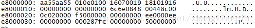
读slave ID为0x50的IC 的前112个byte内容并显示。
i2c md 0x50 0 0x70 在我的u-boot下输出:
0000: aa 55 aa 55 01 0e 01 00 16 07 00 19 18 10 19 16
0010: 00 00 00 00 00 00 00 00 6c 6e 08 48 00 44 8c 00
0020: 0c 02 00 00 f5 00 00 00 00 00 00 00 ee 00 00 ee
0030: 00 00 00 00 00 02 87 fc 00 00 00 00 50 00 00 00
0040: 00 00 00 00 00 00 00 28 09 12 41 c0 f0 3f 3f 3f
0050: 09 12 41 c4 ff 00 3f 3f 09 12 40 10 00 00 01 01
0060: 09 12 41 30 00 00 00 0c 08 13 80 40 4a 43 27 59 另一种方式是将内容读到memory当中,然后使用md 命令显示内存内容。
i2c read 0x50 0 0x70 1000000
md 1000000
咦,如果我不知道我能操作哪些i2c bus?哪些i2c设备咋办呢?
没关系,可以使用i2c bus 看下你系统中有几个i2c总线。
我的硬件平台上有两个i2c bus。
Bus 0:  fsl_0
Bus 1: fsl_1使用i2c dev 可以查看现在操作的是哪个bus。
Current bus is 0
使用i2c dev 1 可以将当前bus切换为bus 1.
使用i2c probe 可以检测出当前bus上有多少个设备,且slaveID是多少?
Valid chip addresses: 08 1A 1E 2F 32 36 4B 4F 50 52 56 60 61 68 6D 70 71向slaveID为0x50的设备的00–02地址写入00 01 02。
i2c mw 0x50 0 0
i2c mw 0x50 1 1
i2c mw 0x50 2 2
这种方式每次只能写一个值,或者使用同一个值填充不同偏移量的地址。
i2c mw 0x6d 0 8 8
i2c md 0x6d 0 10
输出内容:
0000: 08 08 08 08 08 08 08 08 00 00 28 00 dc 00 00 00
可以看到我们00-07的8个值都被写成了0x08。
我们还有另一种方法:先把需要写的值弄到内存里,然后使用i2c write 命令写多个字节。
mw.b 1000000 00
mw.b 1000001 01
mw.b 1000002 02
md 1000000
01000000: 000102ef deadbeef deadbeef deadbeef
01000010: deadbeef deadbeef deadbeef deadbeef
在内存地址中我们准备好了要写的3个数据。
使用i2c write 1000000 0x50 0 3 一次性将3个数值写入i2c设备。
这样,我们可以使用tftp Xmodem等方式来将你要写的内容下载到内存中,然后一次性写入i2c设备。
总结下:i2c 设备的写有两种方式,一种是单个字节内容字节的写,一种是多个字节的写。前者适合改写单个字节内容,后者适合改写多个字节。
另外,u-boot中有关于address[.0, .1, .2] 的详细说明,一般来说i2c设备的address有这样3中情况:
1,设备总的offiset 小于255,单个byte的address就足够了,默认就是这种情况,也就是i2c mw 0x50 0.1 0 。
2,设备的offset需要2个byte,设备的address要两个byte才能访问到所有的offiset,也就是 i2c mw 0x50 287.2 0
3,有些不需要address这个参数,也就是i2c mw 0x50 0.0 0
详细的见下面的解释。
“/*
* I2C Functions similar to the standard memory functions.
* There are several parameters in many of the commands that bear further
* explanations:
* {i2c_chip} is the I2C chip address (the first byte sent on the bus).
* Each I2C chip on the bus has a unique address. On the I2C data bus,
* the address is the upper seven bits and the LSB is the “read/write”
* bit. Note that the {i2c_chip} address specified on the command
* line is not shifted up: e.g. a typical EEPROM memory chip may have
* an I2C address of 0x50, but the data put on the bus will be 0xA0
* for write and 0xA1 for read. This “non shifted” address notation
* matches at least half of the data sheets :-/.
* {addr} is the address (or offset) within the chip. Small memory
* chips have 8 bit addresses. Large memory chips have 16 bit
* addresses. Other memory chips have 9, 10, or 11 bit addresses.
* Many non-memory chips have multiple registers and {addr} is used
* as the register index. Some non-memory chips have only one register
* and therefore don’t need any {addr} parameter.
* The default {addr} parameter is one byte (.1) which works well for
* memories and registers with 8 bits of address space.
* You can specify the length of the {addr} field with the optional .0,
* .1, or .2 modifier (similar to the .b, .w, .l modifier). If you are
* manipulating a single register device which doesn’t use an address
* field, use “0.0” for the address and the “.0” length field will
* suppress the address in the I2C data stream. This also works for
* successive reads using the I2C auto-incrementing memory pointer.
* If you are manipulating a large memory with 2-byte addresses, use
* the .2 address modifier, e.g. 210.2 addresses location 528 (decimal).
“`
4.读写内存、寄存器
RISC指令集的计算机,地址是统一编址的,我们可以使用md mw 等命令来读写寄存器、内存、nor flash等。
md - memory display
Usage:
md [.b, .w, .l] address [# of objects]
mw - memory write (fill)
Usage:
mw [.b, .w, .l] address value [count]
按字节读取内存内容
md.b 1000000 5
输出:
01000000: 00 01 02 ef de
按word读取内存内容
md.w 1000000 5
输出:
01000000: 0001 02ef dead beef dead
按double word读取内存内容
md.l 1000000 5
输出:
01000000: 000102ef deadbeef deadbeef deadbeef
01000010: deadbeef
写内存或者寄存器同样的操作:
mw.w 1000000 8 10
md.w 1000000 10
输出:
01000000: 0008 0008 0008 0008 0008 0008 0008 0008
01000010: 0008 0008 0008 0008 0008 0008 0008 0008
5.网络命令 ping tftp
ping命令是用来检测在u-boot下网络是否正常的。tftp是用来通过网络下载文件的。
u-boot有两个和网络有关系的环境变量:ipaddr、serverip,用来表示本机的IP地址和tftp server IP地址。
pri ipaddr
ipaddr=192.168.56.222
pri serverip
serverip=192.168.56.163
设置好这两个环境变量后,连接上网线。使用ping 命令检测网络是否正常工作。
ping 192.168.56.163
若输出:
host 192.168.56.163 is alive
网络正常。
使用tftp命令下载文件。
设置好tftp server服务器后,
tftp 1000000 uImage.bin
Using FM1@DTSEC1 device
TFTP from server 192.168.56.163; our IP address is 192.168.56.222
Filename ‘uImage.bin’.
Load address: 0x1000000
Loading: ##################################################
469.7 KiB/s
done
Bytes transferred = 4820574 (498e5e hex)
6.网络PHY芯片操作MDIO/MII
调试、操作PHY的命令主要有MDIO 和MII。这两个命令的区别是:MII可以访问不同MII总线上设备的Reg,MDIO命令只能访问当前MII总线的PHY Reg。
mii
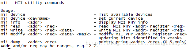
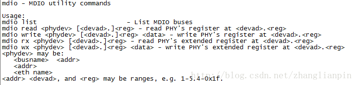
mdio
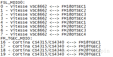
使用mii device 可以查看该系统有几个MDIO总线。
我的平台上输出:
MII devices: 'FSL_MDIO0' 'FM_TGEC_MDIO'
Current device: 'FSL_MDIO0'
说明我的平台上有两个MDIO总线,现在使用的是FSL_MDIO0
只要涉及到总线,就意味着有多个设备都接到这个BUS上,那就要区分这些个设备,怎么区分呐?给挂载到这个BUS上的设备分配一个唯一的ID,在MII总线里叫phyID。
我怎么知道我的硬件平台有哪些phy可以操作,这些phy的phyID是多少?
u-boot中可以使用mdio list 查看下,
若没有输出,可以参考原理图,原理设计时会通过硬件设置好各个phy的phyID。
PHY的各个控制、管理寄存器有一个统一的offset和规范,见IEEE802.3 clause 22(千兆PHY)和IEEE802.3 clause 45(万兆PHY)。该规范还定义了MII总线的通讯协议、时序等内容。
假设我们想知道PHY的link status,我们可以
mii read 0 1 (访问的phyID为0的PHY的offset为1的寄存器的值)
规范定义PHY寄存器offset为1的表示PHY status
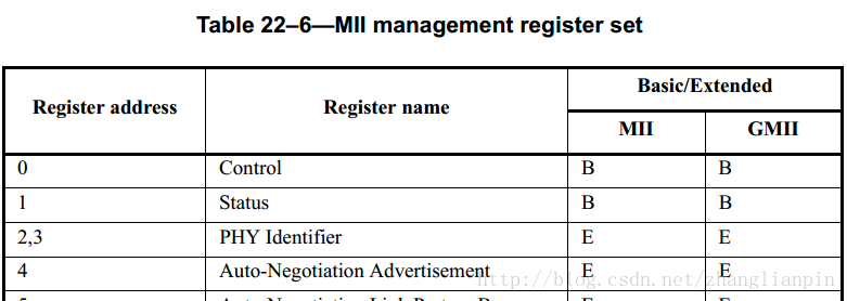
PHY status寄存器的定义见下图:
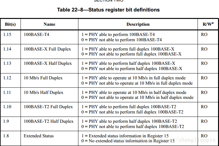
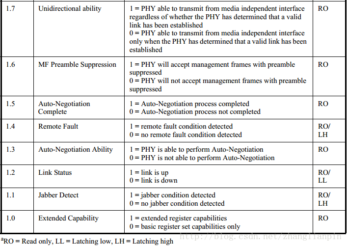
返回值:
79ED
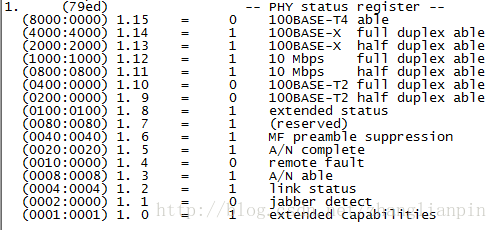
我们可以将上述返回值,转换成二进制数,对照规范定义来翻译含义。当然,这有点枯燥。
我们可以使用mii dump 0 1
mdio 的操作和mii 的操作差不多。主要是理解phyID和reg参数和ieee802.3 clause22和clause45规范。
7.NADN Flash 操作
Nand Flash作为块设备使用,不支持随机读写。且Nand Flash芯片每一位(bit)只能从1变为0,而不能从0变为1,所以在对其进行写入操作之前要一定将相应块擦除(擦除即是将相应块得位全部变为1).
.读数据(将nandflash中的数据读取到内存中):
nand read - addr off|partition size
nand read 1000000 0 10
主要的参数包括:读取到的数据存放地址(mem addr)、offset(page-aligned)、size(data size)。
nand read 1000000 1000 10
offset要求为page-aligned,我使用的这款Nand Flash的page size为4k。
写数据(将内存中的数据写入nand flash):
.擦除
nand erase 0 10
.写数据
nand write 1000000 0 10
8.Nor Flash操作
norflash支持随机读,在ASIC指令集的CPU上norflash地址一般映射到统一编址地址上,因此可以使用md 命令读取数据。需要查看硬件设计原理图和CPU的datasheet来确定表示norflash 的地址范围。
md e8000000 10
在我的硬件平台上0xe8000000-0xEFFFFFFF是norflash的地址范围。
norflash的写操作需要特定的时序,且需要先擦除再写入。因此需要专门的驱动程序,这个驱动程序可以是软件实现也可以是CPU硬件支持。
9.SPI Flash操作
检测系统中存在哪些spi 设备
sf probe
我系统的输出:
SF: Detected W25Q256FV with page size 64 KiB, total 32 MiB
SPI flash也是一种flash存储器,当然写之前也要擦除操作。
读数据:
sf read 1000000 0 10
写数据:
.擦除
sf erase 0 10
.写入
sf write 1000000 0 10
10.USB 存储设备操作
USB 是一个标准的块设备,读写都要按照block为最基本的单位。
扫描USB 设备
usb start
我自己平台上的输出:
starting USB...
 USB0: USB EHCI 1.00
 scanning bus 0 for devices... 2 USB Device(s) found
 USB1: USB EHCI 1.00
 scanning bus 1 for devices... 1 USB Device(s) found
 scanning usb for storage devices... 1 Storage Device(s) found
可以看到,我的硬件平台上有两个USB Host controller,其中USB1 bus上插了一个U盘,被识别为USB存储设备。
U盘的读写可以按照无文件系统形式进行裸读写。
读(到内存):
usb read 1000000 0 10
写(从内存到U盘):
usb write 1000000 0 10
一般地,使用U盘主要是从普通PC机上Copy文件到目标单板。一般u-boot下支持FAT格式的文件系统。
使用以下命令读取一个FAT文件系统下的文件。
fatload usb 0 1000000 test.bin
fatload 的usage:
fatload <interface> [<dev[:part]> [<addr> [<filename> [bytes [pos]]]]]
 - Load binary file 'filename' from 'dev' on 'interface'
 to address 'addr' from dos filesystem.
 'pos' gives the file position to start loading from.
 If 'pos' is omitted, 0 is used. 'pos' requires 'bytes'.
 'bytes' gives the size to load. If 'bytes' is 0 or omitted,
 the load stops on end of file.
 If either 'pos' or 'bytes' are not aligned to
 ARCH_DMA_MINALIGN then a misaligned buffer warning will
 be printed and performance will suffer for the load.
其中dev[:part]表示那个USB设备,可以通过usb dev 来查看。
我的平台输出:
USB device 0: Vendor: Rev: 1.00 Prod:
 Type: Removable Hard Disk
 Capacity: 7424.0 MB = 7.2 GB (15204352 x 512)
可见我的U盘的USB设备号是0。
11.硬盘操作
查看系统中的SATA盘
sata info
SATA device 0: Model: RTBMB256VBM8EWEY Firm: T1064 Ser#: FN0215122450000198
 Type: Hard Disk
 Capacity: 244198.3 MB = 238.4 GB (500118192 x 512)
 SATA device 1: Model: Firm: Ser#:
 Type: Hard Disk
 Capacity: not available
可见,系统中有两个SATA接口,其中有一个238.4G的sata硬盘。
裸读写操作:
读(到内存):
sata read 1000000 0 10
写(从内存到SATA盘):
sata write 1000000 0 10
我们使用SATA盘,不会直接裸操作,一般会在文件系统层面进行文件操作。
在linux下常用的文件系统有:ext2、ext3、ext4。
我们这里使用ext2文件系统,将SATA盘格式化成ext2文件系统格式,在linux主机上Copy文件到SATA盘,然后连接到目标平台。
读文件:
ext2load sata 0:1 1000000 /boot/uImage
12. SD卡操作
块设备,也是一种Flash,写之前也需要Erase。
查看系统中的SD卡信息,
mmc info
我的系统输出:
Device: FSL_SDHC
 Manufacturer ID: 1d
 OEM: 4144
 Name: SD
 Tran Speed: 50000000
 Rd Block Len: 512
 SD version 3.0
 High Capacity: Yes
 Capacity: 3.8 GiB
 Bus Width: 4-bit
 Erase Group Size: 512 Bytes
读:
mmc read 1000000 0 10
写:
1.擦除
2.写入
mmc erase 0 10
mmc write 1000000 0 10
当然,如果SD卡里有文件系统,FAT、ext2等。我们可以使用fatload、ext2load来加载文件系统里的文件。具体指令这里略。
13.PCIE操作
PCIE 设备很常见,传输速度高,支持热拔插。
查看系统中的PCIE设备。
pci 1
我的平台输出:
`Scanning PCI devices on bus 1
BusDevFun VendorId DeviceId Device Class Sub-Class
01.00.00 0x8086 0x1583 Network controller 0x00
01.00.01 0x8086 0x1583 Network controller 0x00 pci header 01.00.00
我的系统pcie bus 1上插入了一个pcie网卡设备。
vendor ID = 0x8086
 可以列出bus 1的00号设备00号功能,这一个具体device的pcie配置信息。
 我的平台输出如下:
device ID = 0x1583
command register ID = 0x0006
status register = 0x0010
revision ID = 0x02
class code = 0x02 (Network controller)
sub class code = 0x00
programming interface = 0x00
cache line = 0x08
latency time = 0x00
header type = 0x80
BIST = 0x00
base address 0 = 0xe100000c
base address 1 = 0x00000000
base address 2 = 0x00000000
base address 3 = 0xe180000c
base address 4 = 0x00000000
base address 5 = 0x00000000
cardBus CIS pointer = 0x00000000
sub system vendor ID = 0x8086
sub system ID = 0x0001
expansion ROM base address = 0xe1880000
interrupt line = 0x00
interrupt pin = 0x01
min Grant = 0x00
max Latency = 0x00 pci modify
还可以通过pci write` 等命令修改PCIE的CFG寄存器,用于配置pcie设备。
当然,关于PCIE设备的调试,已经超出了本文的范围。感兴趣的可以参考PCIE3.0 Spec。
14.通过串口收发文件Xmodem
有些时候,硬件刚出炉,可能像网口、USB bus都还没调试通过。这个时候可能只有串口是好用的,那我能用串口传输文件吗?当然可以,基于串口的文件传输协议:Xmodem。
loadx 1000000
u-boot会等待用户传输文件。
## Ready for binary (xmodem) download to 0x01000000 at 115200 bps...
 CCC
我使用的串口调试工具是SecureCRT,发送Xmodem协议格式的文件方法:
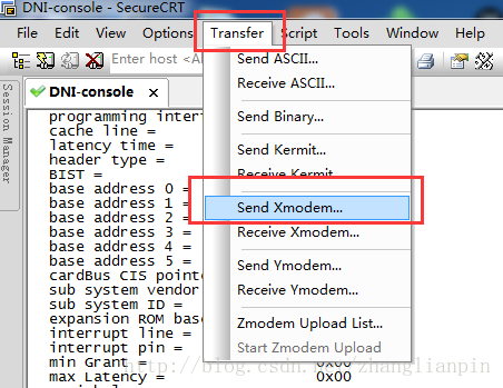
就是传输速度慢了点,平均4K/S(115200buard情况下)。
15.使用u-boot执行script文件
u-boot的CLI即有interactive和noninteractive,说的直白点。就是即可以人工输入不同的命令来实现你的目的,也可以执行u-boot脚本。
比如:
echo ===== DMA Desc 1 ===== loadx 1000000
mw.l 100000 0 1000 #Init to zero
mw.l 100000 babeface 1000 #Write "babeface"
将上述内容保存为一个文件,通过tftp/Xmodem方式下载到内存里,然后执行此脚本。
source 0x1000000`
发送文件
然后u-boot就会顺序执行你的脚本文件里的内容。是不是挺好玩的。
………………结束……………………


 1万+
1万+


 被折叠的 条评论
为什么被折叠?
被折叠的 条评论
为什么被折叠?
 到【灌水乐园】发言


