


一、Colmap安装
Linux中直接输入命令行sudo apt install colmap即可
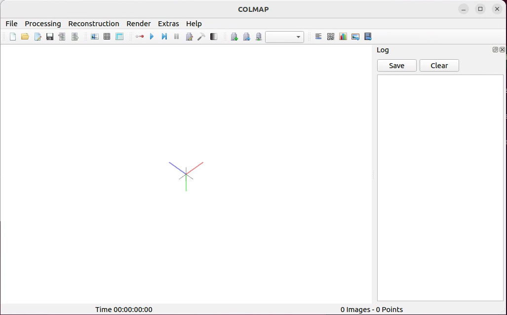
输入colmap gui即可打开图形化界面
二、标定
2.1 准备工作
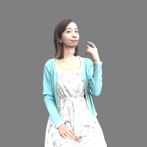
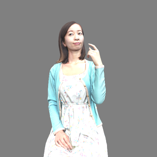
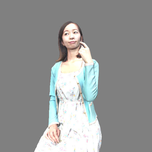
创建工作文件夹~/calibration,其中创建images文件夹,存放有从左到右拍摄的三视角视图,分别依次为cam0.png,cam1.png,cam2.png。作者的图像内容是点云在unity中的虚拟环拍图像,故相机有相同的内参。点云素材来自:091 Aya Free 3D Model - .obj .c4d .max - Free3D
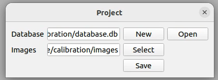
菜单栏—File—New Project:
①Database栏点击New,进入创建的~/calibration文件夹里,上方输入框内输入数据库名称database,右上角选Save返回;
②Images栏点击Select,进入创建的~/calibration/images文件夹里,右上角点击Open返回。
操作完点击Save。
2.2 特征提取
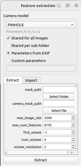
菜单栏— Processing—Feature extraction(左图):
①Camera model选择PINHOLE,普通相机一般是针孔相机模型,即透视投影;
②因为相当于是完全相同的相机拍摄的,所以对于内参fx,fy,cx,cy,勾选Shared for all Images。
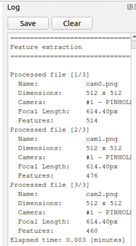
点击Extract,主界面右边就会显示特征提取Log(右图)。
2.1+2.2 等效命令行指令:colmap feature_extractor --database_path calibration/database.db --image_path calibration/images --ImageReader.single_camera 1 --ImageReader.camera_model PINHOLE
2.3 特征匹配
菜单栏— Processing—Feature matching(左图):直接点击Run就行,主界面右侧继续输出Log(右图)。
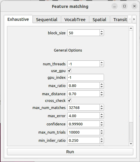
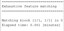
等效命令行指令:colmap exhaustive_matcher --database_path calibration/database.db
2.4 稀疏重建
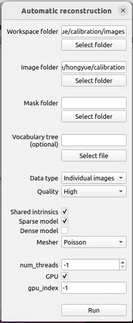
菜单栏—Reconstruction—Automatic reconstruction(左图):
①和一开始类似,上面两个文件夹分别选择~/calibration和~/calibration/images文件夹;
②因为是相同的相机,中间勾选Shared intrinsics。
点击Run,弹出的对话框选OK,主界面右侧继续输出Log(右图)。主界面通过鼠标操作,可以看到三个相机的相对位置。还有一些极其稀疏的点云,得相机比较多,才能看得出目标轮廓。
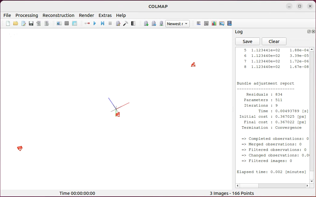
等效命令行指令:colmap automatic_reconstructor --workspace_path calibration --image_path calibration/images --single_camera 1
2.5 结果处理
上述操作完成,可以发现出现了~/calibration/sparse/0文件夹,里面有一些bin文件:
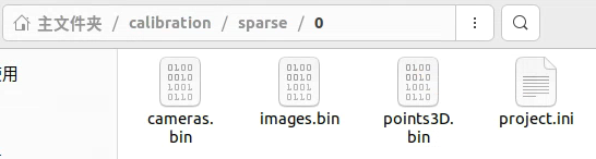
通过命令行指令将这些bin文件转换为txt文件:
colmap model_converter --input_path calibration/sparse/0 --output_path calibration/sparse/0 --output_type TXT
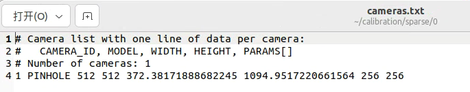
①cameras.txt里面保存了内参信息:
相机序号:1 相机模型:PINHOLE 图像分辨率:512x512
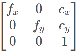
内参矩阵里的参数:fx=372.xxx fy=1094.xxx cx=256 cy=256
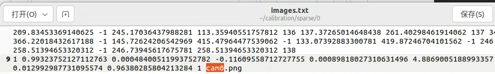
②images.txt里的偶数行保存了外参信息,Ctrl+F搜索图片名称可以看到:
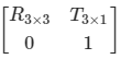
图像序号:1 旋转四元数(后面【第三部分】使用一些函数转换成外参中的旋转矩阵R):
QW= 0.993xxx QX= 0.000xxx QY=-0.116xxx QZ=0.000xxx
平移向量T的三个参数:Tx=4.886xxx Ty=0.012xxx Tz=0.963xxx
三、结果验证
节选并修改了一段github上的代码,python环境需要pip install numpy、python-opencv和transforms3d包,可针对其中两张图片,作为左、右视图进行双视角对极几何验证,将得到的内、外参粘贴到下述camera_k、left_ext_params和right_ext_params矩阵/数组里。
#caliVerify.py
import cv2
import numpy as np
from numpy.linalg import inv
import transforms3d as t3d
left_image = cv2.imread("cam0.png")
right_image = cv2.imread("cam1.png")
left_ext_params=[0.99323752127112763, 0.00048400511993752782, \
-0.11609558712727755, 0.00089818027310631496,\
4.8869005188993357, 0.012992987731095574, 0.96380285804213284]
left_pose=np.zeros([4,4])
left_pose[:3,:3]=t3d.quaternions.quat2mat(left_ext_params[:4])
left_pose[:3,3]=left_ext_params[4:]
left_pose[3,3]=1
right_ext_params=[0.99999870258601886, -0.00020446045335147645, \
-0.0015852453856825995, 0.00020004816728340241,\
0.028774206458871632, -0.018549169482988754, 0.36068280018336535]
right_pose=np.zeros([4,4])
right_pose[:3,:3]=t3d.quaternions.quat2mat(right_ext_params[:4])
right_pose[:3,3]=right_ext_params[4:]
right_pose[3,3]=1
camera_k = np.asarray([ [372.38171888682245, 0, 256],
[0, 1094.9517220661564, 256],
[0, 0, 1]])
# test the epipolar line
left2right = np.dot(inv(right_pose), left_pose)
test_point = np.asarray([left_image.shape[1] //2, left_image.shape[0] *9 //10, 1])
far_point = np.dot(inv(camera_k), test_point) * 50.0
far_point = np.append(far_point, 1)
far_point = np.dot(left2right, far_point)
far_pixel = np.dot(camera_k, far_point[0:3])
far_pixel = (far_pixel / far_pixel[2])[0:2]
near_point = np.dot(inv(camera_k), test_point) * 0.1
near_point = np.append(near_point, 1)
near_point = np.dot(left2right, near_point)
near_pixel = np.dot(camera_k, near_point[0:3])
near_pixel = (near_pixel / near_pixel[2])[0:2]
cv2.line(right_image,
(int(far_pixel[0] + 0.5), int(far_pixel[1] + 0.5)),
(int(near_pixel[0] + 0.5), int(near_pixel[1] + 0.5)), [0,0,255], 4)
cv2.circle(left_image,(int(test_point[0]), int(test_point[1])), 4, [0,0,255], -1)
result_image = np.concatenate((left_image, right_image), axis=1)
cv2.imshow("result", result_image)
cv2.waitKey(0)
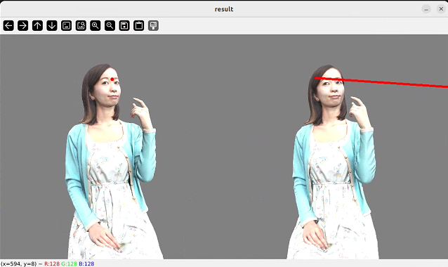
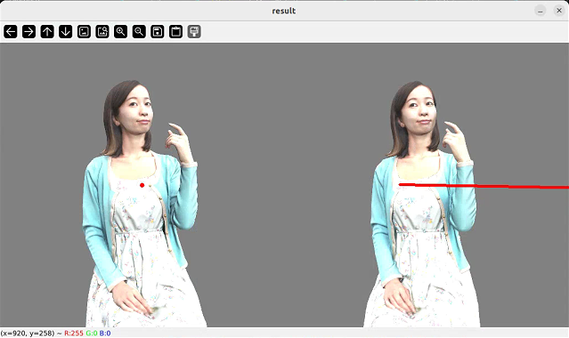
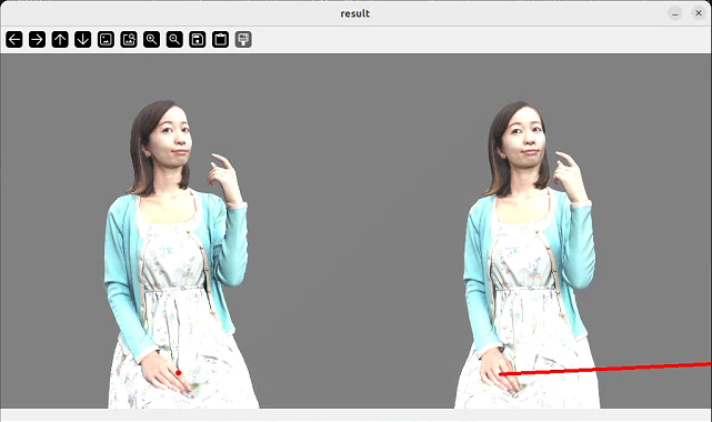
显示结果中,左图中的红点所示内容在右图中要被红线穿过,标定才较为准确。可以更改代码中的test_point位置,多试几次。


 793
793

 被折叠的 条评论
为什么被折叠?
被折叠的 条评论
为什么被折叠?
 到【灌水乐园】发言


