


Author: Wind
OS:
IDE:
MCU: STM32 F303 VC T6
一、硬件设计
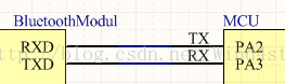
1.MCU使用USART2,USART2_TX——PA2, USART2_RX——PA3
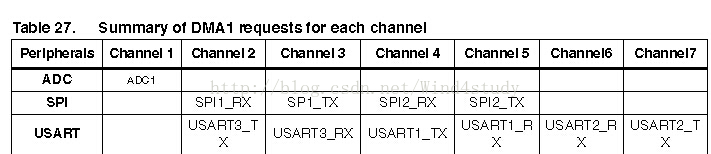
2.DMA:查看ST官方网站的STM32F3参考手册(官网下载),使用DMA1
3.MCU与蓝牙模块连接:
二、程序代码
1.USART配置:查看ST官方固件库手册(官网下载),按顺序进行配置,以下复制原文:
//23.2 USART Firmware driver API description
The following section lists the various functions of the USART library.
23.2.1 How to use this driver
1. Enable peripheral clock using RCC_APB2PeriphClockCmd(RCC_APB2Periph_USART1, ENABLE) function for USART1 or using RCC_APB1PeriphClockCmd(RCC_APB1Periph_USARTx, ENABLE) function for USART2, USART3, UART4 and UART5.
2. According to the USART mode, enable the GPIO clocks using RCC_AHBPeriphClockCmd() function. (The I/O can be TX, RX, CTS, or and SCLK). 3. Peripheral's alternate function: Connect the pin to the desired peripherals' Alternate Function (AF) using GPIO_PinAFConfig() function.
Configure the desired pin in alternate function by: GPIO_InitStruct->GPIO_Mode=
GPIO_Mode_AF.
Select the type, pull-up/pull-down and output speed via GPIO_PuPd,
GPIO_OType and GPIO_Speed members.
Call GPIO_Init() function.
4. Program the Baud Rate, Word Length , Stop Bit, Parity, Hardware flow control and
Mode(Receiver/Transmitter) using the SPI_Init() function.
5. For synchronous mode, enable the clock and program the polarity, phase and last bit
using the USART_ClockInit() function.
6. Enable the NVIC and the corresponding interrupt using the function
USART_ITConfig() if you need to use interrupt mode.
7. When using the DMA mode:
Configure the DMA using DMA_Init() function.
Active the needed channel Request using USART_DMACmd() function.
8. Enable the USART using the USART_Cmd() function.
9. Enable the DMA using the DMA_Cmd() function, when using DMA mode.
2.DMA配置
//9.2 DMA Firmware driver API description
1. Enable The DMA controller clock using
2. Enable and configure the peripheral to be connected to the DMA channel (except for
3. For a given Channel, program the Source and Destination addresses, the transfer
4. Enable the NVIC and the corresponding interrupt(s) using the function
5. Enable the DMA channel using the DMA_Cmd() function.
6. Activate the needed channel Request using PPP_DMACmd() function for any PPP
7. Optionally, you can configure the number of data to be transferred when the channel
8. To control DMA events you can use one of the following two methods:
a. Check on DMA channel flags using the function DMA_GetFlagStatus().
b. Use DMA interrupts through the function DMA_ITConfig() at initialization phase
3.开始发送,使能各功能模块
源代码:</pre><pre name="code" class="cpp">
<pre name="code" class="cpp">/**************************************************/
// Header:
// File Name: main.h
// Author: Wind
// Date: 2015.01.25
/**************************************************/
#ifndef MAIN_H
#define MAIN_H
#include "stm32f30x.h"
#include "stm32f30x_rcc.h"
#include "stm32f30x_dma.h"
#include "Config.h"
#endif
/*****************************************/
/**************************************************/
// Header:
// File Name: main.c
// Author: Wind
// Date: 2015.01.25
/**************************************************/
#include "main.h"
#define BT_TX_BUFFER_LENGTH 26 //发送26个字母
static uint8_t BT_TX_Buffer[BT_TX_BUFFER_LENGTH];
/**************************************************/
int main()
{
uint8_t i=0,data='A';
BTUSARTConfig(115200);//波特率115200
BTDMAConfig((uint32_t) BT_TX_Buffer,BT_TX_BUFFER_LENGTH);
//准备好待发送的数据
for (i=0;i<BT_TX_BUFFER_LENGTH;i++,data++)
{
BT_TX_Buffer[i] = data;
}
//开始发送
StartDataTransfer();
while(1); //持续发送,同时CPU可以做其他事情
}
/**********************************************************/
/**************************************************/
// Header:
// File Name: Config.h
// Author: Wind
// Date: 2015.01.25
/**************************************************/
#ifndef CONFIG_H
#define CONFIG_H
#include "stm32f30x.h"
#include "stm32f30x_rcc.h"
#include "stm32f30x_dma.h"
// Bluetooth port settings
#define BT_USART_IO_PORT GPIOA
#define BT_TX_PIN GPIO_Pin_2
#define BT_RX_PIN GPIO_Pin_3
#define BT_TX_SOURCE GPIO_PinSource2
#define BT_RX_SOURCE GPIO_PinSource3
#define BT_USART_GPIO_CLK RCC_AHBPeriph_GPIOA
#define BT_USART_CLK RCC_APB1Periph_USART2
#define BT_TX_AF GPIO_AF_USART2
#define BT_RX_AF GPIO_AF_USART2
#define GPIO_AF_USART2 GPIO_AF_7
#define BT_USART_PORT USART2
#define BT_USART_TDR_ADDRESS ((uint32_t)USART2 + 0x28)
#define BT_USART_RDR_ADDRESS ((uint32_t)USART2 + 0x24)
#define BT_USART_DMA_PORT DMA1
#define BT_USART_DMA_CLK RCC_AHBPeriph_DMA1
#define BT_USART_TX_DMA_CHANNEL DMA1_Channel7
#define BT_USART_RX_DMA_CHANNEL DMA1_Channel6
#define BT_USART_TX_DMA_FLAG_TCIF DMA1_FLAG_TC7
#define BT_USART_RX_DMA_FLAG_TCIF DMA1_FLAG_TC6
//Function declaration
void BTUSARTConfig(uint32_t baudrate);
void BTDMAConfig(uint32_t DataAddr,uint8_t dataLength);
void StartDataTransfer(void);
#endif
/****************************************************************/
/**************************************************/
// Header:
// File Name: Config.c
// Author: Wind
// Date: 2015.01.25
/**************************************************/
#include "Config.h"
/**************************************************/
//USART配置
void BTUSARTConfig(uint32_t baudrate)
{
USART_InitTypeDef USART_InitStructure;
GPIO_InitTypeDef GPIO_InitStructure;
RCC_AHBPeriphClockCmd(BT_USART_GPIO_CLK, ENABLE);
RCC_APB1PeriphClockCmd(BT_USART_CLK, ENABLE);
GPIO_InitStructure.GPIO_Pin = (BT_TX_PIN | BT_RX_PIN);
GPIO_InitStructure.GPIO_Mode = GPIO_Mode_AF; //复用模式
GPIO_InitStructure.GPIO_Speed = GPIO_Speed_50MHz;
GPIO_InitStructure.GPIO_OType = GPIO_OType_PP;
GPIO_InitStructure.GPIO_PuPd = GPIO_PuPd_UP;
GPIO_Init(BT_USART_IO_PORT, &GPIO_InitStructure);
GPIO_PinAFConfig(BT_USART_IO_PORT, BT_TX_SOURCE, BT_TX_AF);
GPIO_PinAFConfig(BT_USART_IO_PORT, BT_RX_SOURCE, BT_RX_AF);
USART_InitStructure.USART_BaudRate = baudrate;
USART_InitStructure.USART_WordLength = USART_WordLength_8b;
USART_InitStructure.USART_StopBits = USART_StopBits_1;
USART_InitStructure.USART_Parity = USART_Parity_No;
USART_InitStructure.USART_HardwareFlowControl = USART_HardwareFlowControl_None;
USART_InitStructure.USART_Mode = USART_Mode_Rx | USART_Mode_Tx;
USART_DeInit(BT_USART_PORT);
USART_Init(BT_USART_PORT, &USART_InitStructure);
USART_Cmd(BT_USART_PORT, ENABLE);
}
//DMA配置
//para:dataAddr:Transffer data address;dataLength:Transffer data length
void BTDMAConfig(uint32_t dataAddr,uint8_t dataLength)
{
DMA_InitTypeDef DMA_InitStructure;
RCC_AHBPeriphClockCmd(RCC_AHBPeriph_DMA1,ENABLE);
DMA_StructInit(&DMA_InitStructure);
DMA_DeInit(BT_USART_TX_DMA_CHANNEL);
DMA_InitStructure.DMA_PeripheralBaseAddr = BT_USART_TDR_ADDRESS;
DMA_InitStructure.DMA_MemoryBaseAddr = dataAddr;
DMA_InitStructure.DMA_DIR = DMA_DIR_PeripheralDST; //外设作为发送目的地
DMA_InitStructure.DMA_BufferSize = dataLength;
DMA_InitStructure.DMA_PeripheralInc = DMA_PeripheralInc_Disable;
DMA_InitStructure.DMA_MemoryInc = DMA_MemoryInc_Enable;
DMA_InitStructure.DMA_PeripheralDataSize = DMA_PeripheralDataSize_Byte;
DMA_InitStructure.DMA_MemoryDataSize = DMA_MemoryDataSize_Byte;
DMA_InitStructure.DMA_Mode = DMA_Mode_Circular; //Ñ»··¢ËÍģʽ
DMA_InitStructure.DMA_Priority = DMA_Priority_VeryHigh;
DMA_InitStructure.DMA_M2M = DMA_M2M_Disable;
DMA_Init(BT_USART_TX_DMA_CHANNEL,&DMA_InitStructure);
}
//开始发送
void StartDataTransfer(void)
{
//清除标志位,否则会丢失部分数据
USART_ClearFlag(BT_USART_PORT,USART_FLAG_TC);
DMA_ClearFlag(BT_USART_TX_DMA_FLAG_TCIF);
//发送
USART_DMACmd(BT_USART_PORT,USART_DMAReq_Tx,ENABLE);
DMA_Cmd(BT_USART_TX_DMA_CHANNEL,ENABLE);
//等待发送完毕
while (!DMA_GetFlagStatus(BT_USART_TX_DMA_FLAG_TCIF));
}
/**********************************************************/
</pre><pre name="code" class="cpp">
<pre name="code" class="cpp">/**************************************************/
// Header:
// File Name: main.h
// Author: Wind
// Date: 2015.01.25
/**************************************************/
#ifndef MAIN_H
#define MAIN_H
#include "stm32f30x.h"
#include "stm32f30x_rcc.h"
#include "stm32f30x_dma.h"
#include "Config.h"
#endif
/*****************************************/
/**************************************************/
// Header:
// File Name: main.c
// Author: Wind
// Date: 2015.01.25
/**************************************************/
#include "main.h"
#define BT_TX_BUFFER_LENGTH 26 //发送26个字母
static uint8_t BT_TX_Buffer[BT_TX_BUFFER_LENGTH];
/**************************************************/
int main()
{
uint8_t i=0,data='A';
BTUSARTConfig(115200);//波特率115200
BTDMAConfig((uint32_t) BT_TX_Buffer,BT_TX_BUFFER_LENGTH);
//准备好待发送的数据
for (i=0;i<BT_TX_BUFFER_LENGTH;i++,data++)
{
BT_TX_Buffer[i] = data;
}
//开始发送
StartDataTransfer();
while(1); //持续发送,同时CPU可以做其他事情
}
/**********************************************************/
/**************************************************/
// Header:
// File Name: Config.h
// Author: Wind
// Date: 2015.01.25
/**************************************************/
#ifndef CONFIG_H
#define CONFIG_H
#include "stm32f30x.h"
#include "stm32f30x_rcc.h"
#include "stm32f30x_dma.h"
// Bluetooth port settings
#define BT_USART_IO_PORT GPIOA
#define BT_TX_PIN GPIO_Pin_2
#define BT_RX_PIN GPIO_Pin_3
#define BT_TX_SOURCE GPIO_PinSource2
#define BT_RX_SOURCE GPIO_PinSource3
#define BT_USART_GPIO_CLK RCC_AHBPeriph_GPIOA
#define BT_USART_CLK RCC_APB1Periph_USART2
#define BT_TX_AF GPIO_AF_USART2
#define BT_RX_AF GPIO_AF_USART2
#define GPIO_AF_USART2 GPIO_AF_7
#define BT_USART_PORT USART2
#define BT_USART_TDR_ADDRESS ((uint32_t)USART2 + 0x28)
#define BT_USART_RDR_ADDRESS ((uint32_t)USART2 + 0x24)
#define BT_USART_DMA_PORT DMA1
#define BT_USART_DMA_CLK RCC_AHBPeriph_DMA1
#define BT_USART_TX_DMA_CHANNEL DMA1_Channel7
#define BT_USART_RX_DMA_CHANNEL DMA1_Channel6
#define BT_USART_TX_DMA_FLAG_TCIF DMA1_FLAG_TC7
#define BT_USART_RX_DMA_FLAG_TCIF DMA1_FLAG_TC6
//Function declaration
void BTUSARTConfig(uint32_t baudrate);
void BTDMAConfig(uint32_t DataAddr,uint8_t dataLength);
void StartDataTransfer(void);
#endif
/****************************************************************/
/**************************************************/
// Header:
// File Name: Config.c
// Author: Wind
// Date: 2015.01.25
/**************************************************/
#include "Config.h"
/**************************************************/
//USART配置
void BTUSARTConfig(uint32_t baudrate)
{
USART_InitTypeDef USART_InitStructure;
GPIO_InitTypeDef GPIO_InitStructure;
RCC_AHBPeriphClockCmd(BT_USART_GPIO_CLK, ENABLE);
RCC_APB1PeriphClockCmd(BT_USART_CLK, ENABLE);
GPIO_InitStructure.GPIO_Pin = (BT_TX_PIN | BT_RX_PIN);
GPIO_InitStructure.GPIO_Mode = GPIO_Mode_AF; //复用模式
GPIO_InitStructure.GPIO_Speed = GPIO_Speed_50MHz;
GPIO_InitStructure.GPIO_OType = GPIO_OType_PP;
GPIO_InitStructure.GPIO_PuPd = GPIO_PuPd_UP;
GPIO_Init(BT_USART_IO_PORT, &GPIO_InitStructure);
GPIO_PinAFConfig(BT_USART_IO_PORT, BT_TX_SOURCE, BT_TX_AF);
GPIO_PinAFConfig(BT_USART_IO_PORT, BT_RX_SOURCE, BT_RX_AF);
USART_InitStructure.USART_BaudRate = baudrate;
USART_InitStructure.USART_WordLength = USART_WordLength_8b;
USART_InitStructure.USART_StopBits = USART_StopBits_1;
USART_InitStructure.USART_Parity = USART_Parity_No;
USART_InitStructure.USART_HardwareFlowControl = USART_HardwareFlowControl_None;
USART_InitStructure.USART_Mode = USART_Mode_Rx | USART_Mode_Tx;
USART_DeInit(BT_USART_PORT);
USART_Init(BT_USART_PORT, &USART_InitStructure);
USART_Cmd(BT_USART_PORT, ENABLE);
}
//DMA配置
//para:dataAddr:Transffer data address;dataLength:Transffer data length
void BTDMAConfig(uint32_t dataAddr,uint8_t dataLength)
{
DMA_InitTypeDef DMA_InitStructure;
RCC_AHBPeriphClockCmd(RCC_AHBPeriph_DMA1,ENABLE);
DMA_StructInit(&DMA_InitStructure);
DMA_DeInit(BT_USART_TX_DMA_CHANNEL);
DMA_InitStructure.DMA_PeripheralBaseAddr = BT_USART_TDR_ADDRESS;
DMA_InitStructure.DMA_MemoryBaseAddr = dataAddr;
DMA_InitStructure.DMA_DIR = DMA_DIR_PeripheralDST; //外设作为发送目的地
DMA_InitStructure.DMA_BufferSize = dataLength;
DMA_InitStructure.DMA_PeripheralInc = DMA_PeripheralInc_Disable;
DMA_InitStructure.DMA_MemoryInc = DMA_MemoryInc_Enable;
DMA_InitStructure.DMA_PeripheralDataSize = DMA_PeripheralDataSize_Byte;
DMA_InitStructure.DMA_MemoryDataSize = DMA_MemoryDataSize_Byte;
DMA_InitStructure.DMA_Mode = DMA_Mode_Circular; //Ñ»··¢ËÍģʽ
DMA_InitStructure.DMA_Priority = DMA_Priority_VeryHigh;
DMA_InitStructure.DMA_M2M = DMA_M2M_Disable;
DMA_Init(BT_USART_TX_DMA_CHANNEL,&DMA_InitStructure);
}
//开始发送
void StartDataTransfer(void)
{
//清除标志位,否则会丢失部分数据
USART_ClearFlag(BT_USART_PORT,USART_FLAG_TC);
DMA_ClearFlag(BT_USART_TX_DMA_FLAG_TCIF);
//发送
USART_DMACmd(BT_USART_PORT,USART_DMAReq_Tx,ENABLE);
DMA_Cmd(BT_USART_TX_DMA_CHANNEL,ENABLE);
//等待发送完毕
while (!DMA_GetFlagStatus(BT_USART_TX_DMA_FLAG_TCIF));
}
/**********************************************************/


 1406
1406


 被折叠的 条评论
为什么被折叠?
被折叠的 条评论
为什么被折叠?
 到【灌水乐园】发言


