


1.POWER MODE SUMMARY
Psoc 4 features five power modes of operations.in order of power consumption and fuctionality,they are active,sleep,deep_sleep,hibenateand stop.if you want to know some aobout typital current and wake up times for each power mode,please see table1.
Table 1. Power Mode Specs
| Power | Current Range (typical)
| Wakeup Time | ||
| PSoC 4200 | PSoC 4200M | PSoC 4200L | ||
| Active | 1.3 mA to 14 mA | – | – | – |
| Sleep | 1.0 mA to 3 mA | 0 | 0 | 0 |
| Deep-sleep | 1.3 µA to 15 µA | 25 µs | 25 µs | 25 µs |
| Hibernate | 150 nA to 1 µA | 2 ms | 0.7 ms | 0.7 ms |
| Stop | 20 nA to 80 nA | 2 ms | 2 ms | 1.9 ms |
2.What are we do for entering low power mode?
2.1 sleep mode
All peripherals are available expect CPU.
Enter sleep mode use API fuction :CySysPmSleep().
2.2 deep-sleep mode
CPU,most peripherals and MHZ clocks are disable.
Enter deep-sleep mode use API fuction:CySysPmDeepSleep().
2.3 hibernate mdoe
All clocks are disable,but logical states are retained.
Enter hibernate mode use API fuction:CySysPmHiberate().
2.4 stop mode
All clocks ,CPU and all peripherals are halted,but logical states are not retained,GPIO states are retained or frozen.
Enter stop mode using the CySysPmStop() API function.
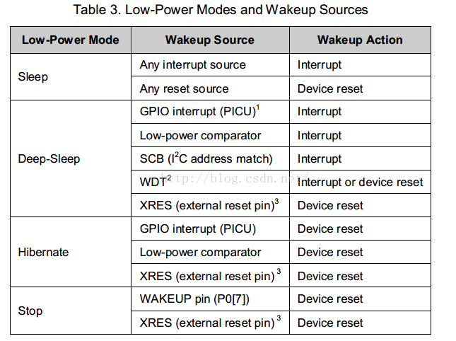
3.How to wake up
3.1 sleep mode
Exit from sleep mode occurs when an interrupt is triggered.
3.2 deep-sleep mode
Exit from deep-sleep mode occurs when an interrupt is triggered.
3.3 hibernate
Exit from hibernate mode occurs when a pin or low-power comparator interrupt is triggered.
3.4 stop mode
Exit from stop mode occurs when the dedicated pin wakeup is triggered, the reset signal goes low, or if power is cycled.
4. Power ReductionTechniques
4.1 Turn Off Unused Components
You can use some API fuction to reduce power,such us mycomponent_Stop,mycomponent_Sleep. then you can wake up them through mycomponent_Start,mycomponent_Wakeup. Mycomponent_Wakeup restores the
Component to its pre-sleep state. The mycomponent_Start() function also brings the Component back into operation, but it is reinitialized to its default state.
4.2 Run Component In a Low Speed
Clocked integrated circuits consume more current as their clock rates increase. Reducing the operating frequency of PSoC 4 components can greatly reduce the current consumption. This technique can be applied to the Cortex-M0 CPU, SAR ADC, digital components, and others.
4.3 Reduce Suply Voltage
Reducing the supply voltage is probably the easiest thing you can do to reduce the overall power consumption. Even
if the current stays the same, reducing the supply voltage from 5 V to 3 V reduces power consumption by 40 percent!
4.4 Use PSoC Device to Gate Current Paths
PCB may contain other components that draw power; the PSoC device can be used to control the current consumed by them.
4.5 Use DMA to Move Data
You can save power any time you offload a task from the CPU and either halt the CPU or let it do something else in parallel. The PSoC 4200M and PSoC 4200L devices have a DMA engine that can be used in active or sleep modes to transfer data with no CPU use.
4.6GPIOs
The GPIOs can continue to drive the external circuitry when the PSoC device is in a low-power mode. This is helpful when you need to hold external logic at a fixed level, but it can lead to wasted power if the pins needlessly source or sink current. You should analyze your design and determine the best state for your GPIOs during low-power operation. If holding a digital output pin at logic 1 or 0 is best, then use the Pins Component’s _Write() API function to set it.
/* Set MyPin to ‘0’ for low power. */
MyPin_Write(0);
Configure all unused GPIOs to Analog HI-Z unless there is a specific reason to use a different drive mode. A Pins Component’s port-wide drive mode may be set using the _SetDriveMode() API function.
/* Set MyPin to Alg HI-Z for low power. */
MyPin_SetDriveMode(MyPin_DM_ALG_HIZ);
The flexibility of PSoC 4 makes it easy to manage GPIO drive modes to prevent unwanted current leakage.
In stop mode, the GPIO drive modes and data registers may be “frozen.” The pin states are automatically frozen by the PSoC Creator stop mode entry API function, CySysPmStop(). They must be “unfrozen” after a wakeup reset to allow their states to change—call the CySysPmUnfreezeIo() API function.
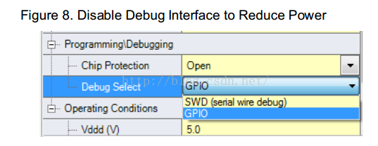
4.7 Debug interface
PSoC 4 supports on-chip debugging. You may observe a higher current consumption than expected while in debug mode. This is normal because the programming and debug interface remains active in all low-power modes.


 1524
1524

 被折叠的 条评论
为什么被折叠?
被折叠的 条评论
为什么被折叠?
 到【灌水乐园】发言


