


转自: http://www.diybl.com/course/6_system/linux/Linuxjs/2007917/71729.html
大概一年多前,曾经在linux下调试过VIA的一款ehci host controller,当时受项目进度以及知识积累所限,未能深入理解EHCI以及linux下的软件层面实现. 随着个人USB技术的不断积累, 近期在工作之余, 写了一些对EHCI以及linux下实现的理解. 选择EHCI作为一个思考和研究的对象的出发点:
1),USB2.0以及 EHCI是非常成功的,这些成功背后必然有技术的因素,对这些导致成功的技术的思考有利于未来在所从事的工作给出成功的设计和实现;
2),EHCI 是usb 2.0 的PC架构下实现方式, 其实现从对处理器能力占用,性能保证以及软件架构都具有一定的通用性,对嵌入式下HC的设计和实现都有较强的参考价值,另外,PC架构下丰富的资源(开放 的EHCI规范, linux usb源码开放,PC环境易于调试等)利于开发者掌握这些技术;
3), EHCI无疑是比较复杂的,对linux ehci的理解和思考有助于提高个人的设计能力.
主要包括以下三个部分 :ehci specification overview, linux ehci device driver 以及主要场景分析 . 由于 个人能力所限 , 错误在所难免 , 但欢迎提出意见 .
1. ehci specification overview [1]
1.1. ehci architectual overview
ehci 规范定义了 usb2.0 host controller 寄存器层面的接口,同时包括了 host controller driver 和 host controller 软硬件之间的接口。 Fig1-1 中灰色部分是 ehci 规范的范围 .
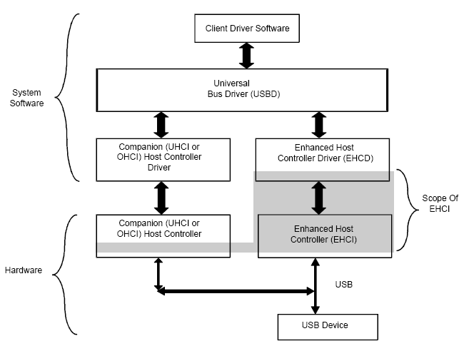
Fig1-1 Universal Serial Bus, Revision 2.0 System Block Diagram
USB 2.0 Host Controller 一般包含 1 个支持高速模式的 eHC 和 0 ~多个支持低速,全速模式的 companion HCs(参考 fig1-2 ),这样可以同时支持三种速度 模式的 usb 设 备。 Port Routing Logic 根据软件的配置以及所插入的 usb device 的 speed mode ,将 port1~portN 映射到 cHCs 或者 eHC 的对应端口:
.EHCD driver 没有配 置 eHC , port routing logic 将所 插入设备的 port 映 射到 cHCs 的对 应 port;
.EHCD driver 配置 了 eHC 后, eHC 是所有 root ports 的默认 owner, 当所插入设备不是高速时, eHC 释放 port owner 给 cHCs, 否则 eHC 保持 port 的 owner.
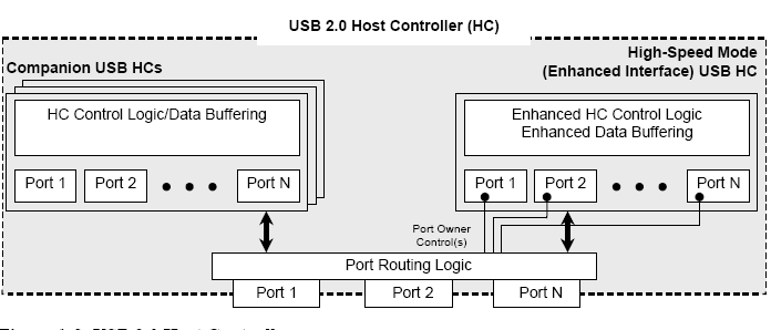
Fig1-2 USB 2.0 Host Controller
Fig1-3 给出了 EHCI 的 general architecture, 包括了 pci configuration registers space, memory-based I/O registers space 以及 shared memory schedule space.
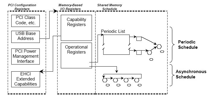
Fig1-3 General Architecture of Enhanced Host Controller Interface
EHCI 对两类传输类型提供了支持: periodic transfer 和 asynchronous transfer. Periodic 类型包括 isochronous and interrupt transfer, asynchronous 类型包括 control 和 bulk transfer.
The periodic schedule is based on a time-oriented frame list that represents a sliding window of time of host controller work items. The asynchronous schedule is a simple circular list of schedule work items that provides a round-robin service opportunity for all asynchronous transfers.
1.1.1. ehci 定义的寄存器接口
主要包括了 pci configuration registers space 以及 register space, 具体参考 ehci specification ch2.
Pci configureation registers space 包括 pci header and device specific registers, USBLEGSUP register, USBLEGCTLSTS register.( 实际上 ehc 不一定非通过 pci device 来实现 , 当不使用 pci device 方式实现时候 , 此处对应的寄存器格式应该会有变化 )
Registers 被划分为两类 : 只读的 capability registers 和 read/write 的操作寄存器 . 操作寄存器用于访问 eHC 的状态 , 控制 eHC 等 , 是 EHCD 访问 eHC 的主要接口之一。
1.2. ehci 定义的 schedule interface
具体参考 ehci specification ch3 。
定义软硬件间数据结构的接口,主要包含如下数据结构 :
Periodic Frame List
定义了包含 1024,512 or 256( 如果 HC 允许 , 可以通过 USBCMD register 配置 ) 个 element 的表格 , 每个element 为一个 4byte-aligned 的指针,可以指向 iTD/QH/siTD/FSTN 等结构 ; 一般需要将该结构对应的表格起始地址写入 PERIODICLISTBASE 寄存器, eHC 结合 FRINDEX 寄存器即可找到当前 frame 所要调度的 periodic schedule 数据结构链表 .
Asynchronous List Queue Head Pointer
该指针指向以 QH 为元素的循环链表,所有 asynchronous transfer(control/bulk) 的 QH 链接至此。
Isochronous (High-Speed) Transfer Descriptor (iTD)
iTD 仅仅被 high speed Isochronous endpoints 所使用,代表该 endpoint 和 usb 设备间一个 frame 内的Isochronous 传 输 , iTD 只可以链接到 Periodic Frame List 中 .
Split Transaction Isochronous Transfer Descriptor (siTD)
通过 usb 2.0 hub(not root hub) 接入 usb bus 的 fs usb Isochronous device , ehci 使用 siTD 向设备对应endpoint 传输数据。 siTD 只可以链接到 Periodic Frame List 中 .
Queue Element Transfer Descriptor (qTD)
qTD 需要链接到 QH 才可以使用, qTD 用于实现 1 个或者多个 USB transaction.
Queue Head
QH 用作实现 Interrupt, bulk 以及 control 传输 , 1 个 QH 包含 0~ 多个 qTD.
Periodic Frame Span Traversal Node (FSTN)
FSTN 用于实现跨 Frame 的 fs/ls split transaction.
1.3. ehci operational model
具体参考 ehci specification ch4 。
Ehci 中该部分主要从 host controller 以及 host controller driver 两 个角度 , 描述了 各自的操作模型 . 从 该部分内容就可以看出 HC 和 HCD 间复杂的接口 .
1.3.1. Periodic schedule
Periodic schedule 用于管理所有 isochronous 和 interrupt 传 输 . Periodic schedule 的基础是 periodic frame list(Fig1-4), 软件将各种 periodic schedule 的数据结构 (iTD,siTD, FSTN 以及 Interrupt QH) 链接到 periodic frame list 的某个 frame 中 , 生成一个 poll rate 从低 到高的树状结构 , 叶子对应的 poll rate 最低 , 树根对应的 poll rate 最高 .
软件设置 USBCMD 寄存器的 periodic schedule enable bit 后 , HC 会从 PERIODICLISTBASE 寄存器
找到 periodic frame list, 结合 FRINDEX 寄存器即可找到当前 frame 所要调度的 transaction 链表 , 这个链表就是从一个树叶到根的一个 path, 在该 frame 对应的 8 个 micro-frame,HC 都会遍历一次该 path, iTD/siTD/interrupt QH 结构中都包含了 micro-frame 相关的 schedule 信息 , 使得 HC 在合 适的 micro-frame 完成对应的 transaction.
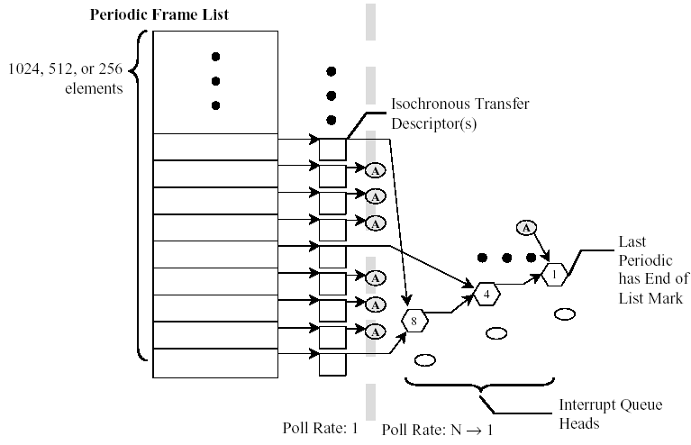
Fig1-4 Example Periodic Schedule
1.3.2. Managing Isochronous Transfers Using iTDs
iTD 主要包含 4 个部分内容 :
. Next Link Pointer .
. Transaction description array (8 uFrame array)
. 7-element 的 buffer page pointer( 最大可支持 7*4KB 传输 )
.endpoint capabilities information(including endpoint addressing, transfer direction, maximum packet size and high-bandwidth multiplier.)
1.3.2.1. from HC view
HC 如何找到 iTD?
HC 使用 FRINDEX[12:3] 去索引 periodic frame list, 得到对应的 periodic frame list element, 该 element 对应的链表在当前帧包含的 8 个 uFrame 中各被扫描 1 次 ( 即当前帧会被连续扫描 8 次 ), HC 在扫描过程中可以将 iTD fetch 到 HC chip 内 . 每个 iTD 包含 8 个 transaction descriptor, HC 通过 FRINDEX[2:0] 来索引对应的 descriptor,进而在 micro-frame 生成对应的 bus transaction.
HC如何解析 iTD 并生成 bus transaction?
如果 (iTD.transaction_descriptor[N] .status & ACTIVE ) == 0, 那么 HC 会忽略该 iTD, 并沿着 NEXT pointer 到达下一个同步 schedule data structure.(N = FRINDEX[2:0] )
如果 (iTD.transaction_descriptor[N] .status & ACTIVE ) == 1, 那么开始解析该 iTD:
. 使用 iTD.transaction_descriptor[N].PG 以及 iTD.transaction_descriptor[N] .Transaction_offset 得到传输数据 buffer 的物理地址
. 使用 endpoint addressing information 以及 I/O bit( 均包含在 iTD 的 endpoint capabilities information )向对应的 endpoint 执行 transaction. 完成后 , HC 会 clear iTD.transaction_descriptor[N].status 的 ACTIVE 位 , 并 且回写其他一些状态信息到 iTD.transaction_descriptor[N].status 中 .
HC 怎样在 uFrame 中执行多个 iso transaction:
Mult field(iTD 的 endpoint capabilities information ) 表示在 一个 uFrame 中 HC 可以向该 endpoint 连续执行几个 transaction, 取值范围为 1~3. 事实上只有 device 的 endpoint 具有这种能力的话 , HCD 才会 在 iTD.Multi 设置对应的值, device 的 endpoint descriptor 中有对应的 Multi 能力描述信息 .
1.3.2.2. from HCD view
上层软件一般会请求 HCD 做一个 HS ISO transfer, 提供如下信息 :
.buffer address 以及 transfer length;
.endpoint 信息 .
HCD 需要将这种请求转化成 HC 可以识别的 iTD, 并将其链接到 periodic frame list 中 . HCD 需要依据如下完成这种转化 :
.endpoint 的 interval 能力 ;
.endpoint 的 MAXPACKETSIZE 能力 ;
.endpoint 的 Multi 能力 ;
.HCD 需要保证同步传输 在每个 uFrame 中 所占据带宽不能超过 80%(USB 2.0 spec 规定 ).
1.3.3. Asynchronous schedule
Asynchronous schedule 用于管理 control 和 bulk 传输 , 这两种传输都使用 QH 数据结构来实现调度 . Asynchronous schedule 从 ASYNCLISTADDR register 得到 control/bulk 传输的 QH 链表 head 地址 , HC 即可遍历/ 解析 asynchronous schedule 的所有 QH 结构 , 生成 bus transaction. 当 HC 完成 asynchronous schedule processing 时候 , 就将上次访问的 QH’s horizontal pointer 保持在
ASYNCLISTADDR register, 以便下次 asynchronous schedule 可以继续上次的遍历 . HC 在如下情况下 , 完成一 次asynchronous schedule 的处理 :
. The end of a micro-frame occurs.
.T he host controller detects an empty list condition.
. The schedule has been disabled via the Asynchronous Schedule Enable bit in the USBCMD
register.
实际上 ,HC 对 control/bulk asynchronous 传输的调度采取 round-robin 的方式 (Fig 1-5).
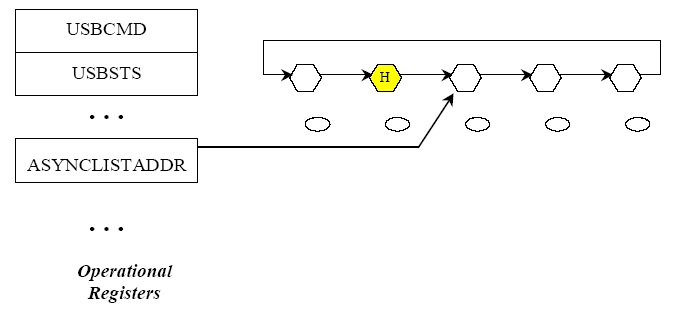
Fig 1-5 General Format of Asynchronous Schedule List
1.3.3.1. Adding Queue Heads to Asynchronous Schedule
从 HCD 角度 , 就是将一个 QH 结构添加到 Asynchronous Schedule list 中 , 算法如下 :
InsertQueueHead (pQHeadCurrent, pQueueHeadNew)
--
-- Requirement: all inputs must be properly initialized.
--
-- pQHeadCurrent is a pointer to a queue head that is already in the active list
-- pQHeadNew is a pointer to the queue head to be added
--
-- This algorithm links a new queue head into a existing list
--
pQueueHeadNew.HorizontalPointer = pQueueHeadCurrent.HorizontalPointer
pQueueHeadCurrent.HorizontalPointer = physicalAddressOf(pQueueHeadNew)
End InsertQueueHead
需要注意的是 , 软件需要保证添加 QH 过程中从 HC 角度保持 schedule 的一致性 : 所有 QH 结构的 pointer field 必须是有效的 .
1.3.3.2. Removing Queue Heads from Asynchronous Schedule
该部分从 HCD 角度说明如何从 asynchronous schedule list 中删除 QH.
HCD unlink QH 的算法如下 :
UnlinkQueueHead (pQHeadPrevious, pQueueHeadToUnlink, pQHeadNext)
--
-- Requirement: all inputs must be properly initialized.
--
-- pQHeadPrevious is a pointer to a queue head that references the
-- queue head to remove
-- pQHeadToUnlink is a pointer to the queue head to be removed
-- pQheadNext is a pointer to a queue head still in the schedule. Software
-- provides this pointer with the following strict rules:
-- if the host software is one queue head, then pQHeadNext must be the
-- same as pQueueheadToUnlink.HorizontalPointer. If the host software is
-- unlinking a consecutive series of queue heads, pQHeadNext must be
-- set by software to the queue head remaining in the schedule.
-- This algorithm unlinks a queue head from a circular list
--
pQueueHeadPrevious.HorizontalPointer = pQueueHeadToUnlink.HorizontalPointer
pQueueHeadToUnlink.HorizontalPointer = pQHeadNext
End UnlinkQueueHead
从算法来看 , 软件操作非常简单 , 但需要注意到 : HC 可以看作和主 CPU 并行运行的的处理器 ,
HC 正在运行过程中删除某个 QH 的话 , 如何使得 HC 内部的状态 ( 比如 cache 了 QH pointer 信息 ) 和内存中实际的链表状态一致呢 ? EHCI 提供了如下方法 :
软件 UnlinkQueueHead ; // 删除了内存中 asynchronous schedule list 中某个 QH
Set IAAD to USBCMD register; // 通知 HC 内存中的某个 asynchronous QH 被删除
使能 IAA 中断 ;
…
IAA IRQ comes //IAA 中断到来, 表示 HC 已经更新其内部状态 , 和内存保持一致
注 :
IAAD: Interrupt on Async Advance Doorbell
IAA : Interrupt on Async Advance
1.3.3.3. Empty Asynchronous Schedule Detection
该部分从 HC 角度说明 .
HC 使用如下信息来发现何时 Asynchronous Schedule 为空 :
.H bit in QH data structure // 由 HC 设置 ,asynchronous schedule 中最多有 1 个 QH 设置了 H bit
// 设置 H 为 1 的 QH 为 head of reclaim list.
. Reclamation bit in USBSTS register //HC 遍历 asynchronous schedule 过程中发现了 H 为 1 的 QH // 即将该位 clear,在开始执行一个 transaction 时候 set to 1
当HC 发现 H bit 为 1 并且 Reclamation bit 为 0 时候 , 认为发现了 empty asynchronous schedule, 即停止遍历asynchronous schedule.
1.3.3.4. Restarting Asynchronous Schedule Before EOF
该部分从 HC 角度说明 .
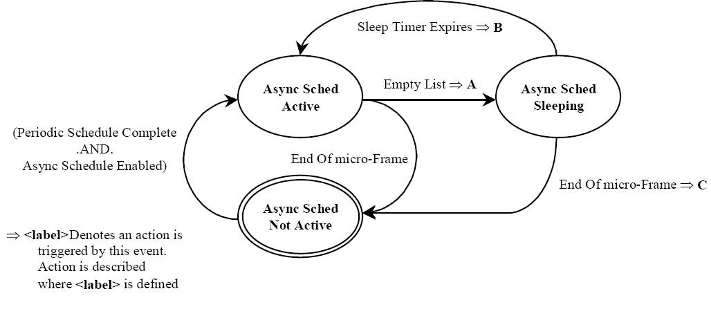
Fig1-6 Example State Machine for Managing Asynchronous Schedule Traversal
检测到 Empty List 时候 ,HC 会停止 traversal 进入 idle. 那么为什么要停止呢 , 毕竟还没有到达 end of micro-frame,还可以执行尽可能多的 transaction. 这是因为导致 empty list 的很多情况都是由于来 自 endpoint 的 Nak/Nyet responses, 如果不停下来那么势必不必要的占用太多 memory 总线带宽 . 那么停下来后 , 是不是 在 current uFrame 就不再asynchronous schedule 呢 ? 其实不是 , 从 Fig1-6 可以看出 , 发现 Empty List 后 , HC 会进入 Async Sched Sleeping 状态, 一般设置该状态的超时时间是 10us, 超时后又会进入 Async Sched Active 状态 , 继续开始 asynchronous schedule.
1.3.3.5. Reclamation Status Bit (USBSTS Register)
该部分从 HCD 角度说明 .
参考 Empty Asynchronous Schedule Detection
1.3.4. Managing Control/Bulk/Interrupt Transfers via Queue Heads
一个 QH 用来管理到一个 endpoint 的数据流 . QH 包含了 endpoint 的能力特性信息 , 包含了执行 bus transaction 的工作区 . QH 使用 qTD 来运行 transaction, 每个 qTD 代表了一个或者多个 Bus transaction. HC 会将执行 qTD bus transaction 时候的状态信息记录在 QH.status field 中 , 当完成一个 qTD 传输后 , 会把 QH.status 回写到 qTD.status 中 , 同时不需要软件干预就可前进到下一个 qTD.
HC对 QH 的通用处理模型 (Fig 1-7) 如下 :
. read a queue head,
. execute a transaction from the overlay area,
. write back the results of the transaction to the overlay area
. move to the next queue head.
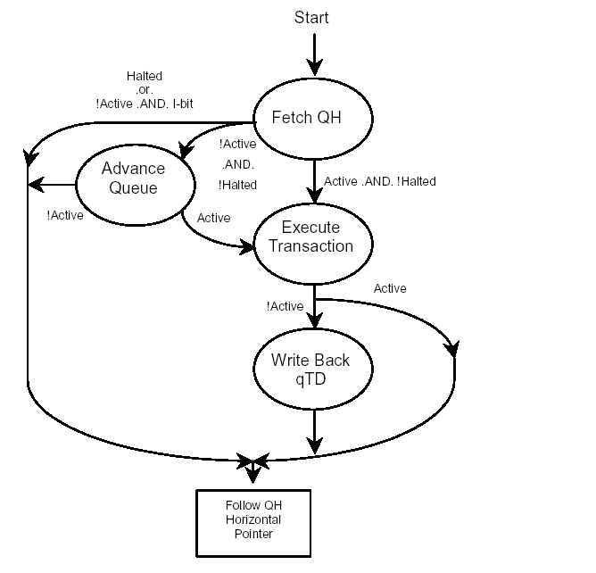
Fig1-7 Host Controller Queue Head Traversal State Machine
Fig 1-7 HC QH traversal State Machine 适 用于各种类型的 QH(control, bulk and Interrupt type), 以及 highspeed transaction , split transaction.
1.3.4.1. Fetch Queue Head
HC 将 QH 结构读入芯片内部后 , 标志该状态结束 .
1.3.4.2. Advance Queue
To advance the queue, the host controller must find the next qTD, adjust pointers, perform the overlay and write back the results to the queue head.
当在 FetchQHD 状态 , HC 发现 QH overlay Active 和 HALT bits 为 0, 即进入 Advance Queue 状态 . 进入该状态后 ,HC 确定 使用哪个指 针来 fetch a qTD, 然后 fetches a qTD 并决定是否做 overlay 操作 ( 当 I-bit == 1 并且Active-bit is 0, HC 跳过对该 QH 的处理 , 退出该状态 , 并且使用当前 QH 的 horizontal pointer 到达下一个schedule data structure).
如果 Bytes to Transfer !=0 并且 Alternate Next qTD Pointer.T ==0, HC 使用 Alternate Next qTD Pointer 来fetches a qTD, 否则 HC 使用 Next qTD Pointer. 如果 Next qTD Pointer.T==1, HC 退出该状态并使用 QH horizontal pointer 到达下一个 schedule data structure.
HC 使用确定好的 pointer fetches the referenced qTD, 如果 the qTD.Active==1, HC 设置 current qTD Pointer值为所确定的取出 qTD 的指针 , 然后 performs the overlay; 如 果 the qTD.Active ==0, HC 退出该状态并使用 QH horizontal pointer 到达下一个 schedule data structure.
HC 按照一系列原则 perform overlay, 写入 QH 结构后 , 退出该状态 .
1.3.4.3. Execute Transaction
进入该状态后, HC 会执行一些 pre-operations, 并在执行 QH 所代表的 transaction 之前做一些
Pre-condition criteria 的测试 这些 pre-operations 和 pre-condition criteria 对于 interrupt QH 和 control/bulk QH 是不同的 .
Interrupt Transfer Pre-condition Criteria
当 QH.S-mask & ( 1<< FRINDEX[2:0] ) != 0 时 ,HC 才会执行该 QH 的 transactions.
Asynchronous Transfer Pre-operations
HC 判断是否需要 reload the NAK Counter field, 如果需要的话 ,reload the NAK Count.
Asynchronous Transfer Pre-condition Criteria
如果 QH. NakCnt !=0 || Reload Nak Counter ==0, HC 才会执行该 QH 的 transactions.
Transfer Type Independent Pre-operations
Load the QH.Multi to HC 内部变量 qHTransactionCounter , HC 该实现对 asynchronous QH 是可选的 , 对 Interrupt QH是必须实现的 .
Transfer Type Independent Pre-condition Criteria
.HC 是否可以在当 前 micro-frame 内完成 QH 的一个 transaction, 如果不可以 , 那么退 出该状态
. 如果 qHTransactionCounter for an interrupt endpoint 等于 0, 那么 HC 退出该状态 .
当所有的 Pre-operations 完成并且满足所有的 Pre-condition Criteria 后 , HC 设置 USBCMD. Reclamation 为 1, 开始使用QH 中的 endpoint 信息执行一个或者多个 transaction, HC 会循环 qHTransactionCounter 次 , 每执行一个 transaction, qHTransactionCounter--. 当如下条件之一发生时 ,
HC 结束该状态 :
. qHTransactionCounter == 0
. The endpoint responds to the transaction with any handshake other than an ACK
. The transaction experiences a transaction error, or
. The Active bit in the queue head goes to a zero, or
. There is not enough time in the micro-frame left to execute the next transaction
每次 transaction 的执行结果会记录在 on-chip overlay area, 如果 transaction 的数据成功传输 ,overlay area 的传输状态更新如下 :
Total Bytes to Transfer -= the number of bytes moved in the transaction
Data toggle bit toggled
Current page offset += the number of bytes moved in the transaction
the C_Page field is updated to the appropriate value (if necessary)
当前 transaction 结束后 , HC 将 transaction 的结果回写到 QH’s overlay area in main memory.
如果 transaction 执行出错 , 传输状态不会更新 , QH.CErr--, QH.status 会记录错误信息 . 如下 事件会导致 HC clear QH.status 的 ACTIVE bit, When the Active bit transitions from a one to a zero, the transfer in the overlay is considered complete.
.CErr field decrements to zero.
. The device responds to the transaction with a STALL PID.
. The Total Bytes to Transfer field is zero after the transaction completes.
. The PID code is an IN, and the number of bytes moved during the transaction is less than the MaximumPacket Length.
. The PID Code field indicates an IN and the device sends more than the expected number of bytes
当 HC 收到 NAK 时 ( 并且 RL==0),HC 将传输结果回写到 QH 的 overlay area. 对于 high speed endpoint, QH 的下述 field需要被更新 :
. NakCnt , dt, Total Bytes to Transfer, C_Page, Status, CERR, and Current Offset
对于 full speed/low speed endpoint, 需要更新 QH 如下的 field:
. C-prog-mask , FrameTag and S-bytes.
1.3.4.4. Write Back qTD
该状态又名 qTD retirement. 在该状态 , HC 将 QH overlay area 回写到 QH. Current qTD Pointer 指向的目标 qTD. 回写的 field 至少包括 :
Total Bytes to Transfer , Cerr, and Status
1.3.4.5. Follow Queue Head Horizontal Pointer
当如下事件发生时 , HC 使用 QH. horizontal pointer 到达下一个 schedule data structure:
. If the Active bit is a one on exit from the Execute Transaction state, or
. When the host controller exits the Write Back qTD state, or
. If the Advance Queue state fails to advance the queue because the target qTD is not active, or
. If the Halted bit is a one on exit from the Fetch QH stat
注:
HC 不需要等待当前 transaction 完成后 , 才 使用 QH. horizontal pointer 读 出下一个 schedule data structure, 但是必须完成当 前 transaction 后 , 才可以执行下一个数据结构中的 transaction.
1.3.4.6. Adding Interrupt Queue Heads to the Periodic Schedule
类似与添加 iTD 到 periodic schedule.
1.3.4.7. Managing Transfer Complete Interrupts from Queue Heads
如果设置了 qTD.IOC, 那么该 qTD 完成后 ,HC 会向 CPU 发出中断请求 .
1.3.5. Ping Control
Ping 协议是 USB2.0 新加的内容 , 主要用于 HS control/bulk endpoint, 为 hs control 和 bulk 传输的 out transaction服务 . Fig 1-8 是 ping control 的状态转换表 .
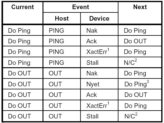
Fig 1-8 Ping Control State Transition Table
1 Transaction Error (XactErr) is any time the host misses the handshake.
2 No transition change required for the Ping State bit. The Stall handshake results in the endpoint being halted (e.g.
Active set to zero and Halt set to a one). Software intervention is required to restart queue.
3 A Nyet response to an OUT means that the device has accepted the data, but cannot receive any more at this time. Host must advance the transfer state and additionally, transition the Ping State bit to Do Ping .
1.3.6. Split Transactions
为了支持通过 usb 2.0 hub 接入总线的 fs/ls 设备 , ehci 引入了 split transaction. Usb2.0 规范在 hs hub 中集成了 transaction translator(tt) 来支持接入的 fs/ls 设备 , tt 充当了 fs/ls host controller 的角色 , 负责执行到 fs/ls 设备的 transaction. Split transaction 是 HC 发到 TT 的 transaction, 包括 start-split transaction (ss) 和 complete-split transaction(cs), ss 用于 HC 请求 TT 发起一个 fs/ls 传输 transaction, cs 用于 HC 向 TT 查询 ss 发起的 transaction是否完成 , 如果完成 , 会向 cs 响应并返回完成结果 .
Ehci 通过 hs hub 的 device address 以及所包含 TT 的 port number 来标识 TT
Ehci 规范中 ,Asynchronous schedule , Interrupt schedule 和 Isochronous schedule 对 split transaction 的实现方 法是不同的 . Asynchronous schedule 通过 QH 支持 split transaction; Interrupt schedule 也是 通过 QH 支持 split transaction, 同时 QH.uFrame S-mask 用于设置 HC 在哪个 micro-frame 发 起 ss, QH.uFrame C-mask 用于设置HC 在哪些 micro-frame 发起 cs, 为了解决跨 frame 问题 ( 即有些 CS 事务需要安排到下一 frame 调度 ), 还引入了FSTN 数据结构 ; Isochronous schedule 单独引入了 siTD 数据结构来支持 fs/ls isochronous split transaction, siTD需要像 iTD 一样被链接到 periodic schedule list 中 .
Split transaction 在 ehci operational model 章节中占据了不少篇幅来说明 , 同时也是 ehci 中的一个难点 .


 1万+
1万+

 被折叠的 条评论
为什么被折叠?
被折叠的 条评论
为什么被折叠?
 到【灌水乐园】发言


