


avr uart打印
We would learn the connection to the LCD first as the connections is a bit complex and here we are using an 8-bit LCD.
我们将首先学习到LCD的连接,因为连接有点复杂,这里我们使用的是8位LCD 。
Simulation
模拟
Explanation
说明
Search these devices from the device selection menu:
从设备选择菜单中搜索以下设备:
- ATmega16
- LM016L (It’s a 16*2 Alphanumeric LCD)
- One Power Terminal
- One Ground terminal
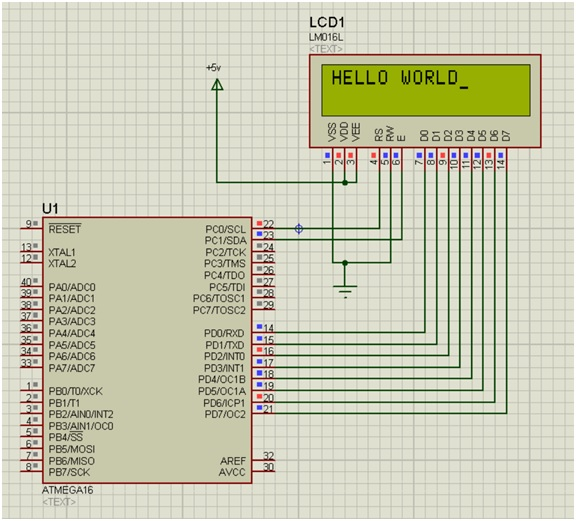
Connect the power terminal from the VDD and VEE of the LCD.
从LCD的VDD和VEE连接电源端子。
Connect the Enable pin (E) and VSS pin to the ground terminal.
将使能引脚(E)和VSS引脚连接到接地端子。
Double click on the Power terminal and write +5V in its properties.
双击电源端子,并在其属性中写入+ 5V 。
Connect the R/S and E pin to the PC0 and PC1 of the ATmega16.
将R / S和E引脚连接到ATmega16的PC0和PC1 。
The next step would be to debug the HEX file in the ATmega16.
下一步将是调试ATmega16中的HEX文件。
Now after all the connections are made we will move forward to the coding section. As the coding for the LCD is bit longer so I won’t be attaching the screenshots from the Atmel Studio.
现在,在完成所有连接之后,我们将前进至编码部分。 由于LCD的编码更长,因此我不会附加Atmel Studio的屏幕截图。
用C代码在LCD上打印HELLO WORLD (C code to print HELLO WORLD on the LCD)
#include <avr/io.h>
#define F_CPU 1000000
#include <util/delay.h>
#define RS0
#define EN1

void lcd_comm (char);
void lcd_data(char);
void lcd_init (void);


int main(void)
{
	lcd_init();
	lcd_data('H');
	lcd_data('E');
	lcd_data('L');
	lcd_data('L');
	lcd_data('O');

	lcd_comm(20);

	lcd_data('W');
	lcd_data('O');
	lcd_data('R');
	lcd_data('L');
	lcd_data('D');

	while(1)
	{

	}
}

void lcd_comm(char x){
	PORTD = x;
	PORTC &= ~(1<<RS);
	PORTC |= 1<<EN;
	_delay_ms(5);
	PORTC &= ~(1<<EN);
}

void lcd_data(char x){
	PORTD = x;
	PORTC |= 1<<RS;
	PORTC |= 1<<EN;
	_delay_ms(5);
	PORTC &= ~(1<<EN);
}

void lcd_init(void){
	DDRD = 0xFF;
	DDRC = 0x03;
	lcd_comm(0x38);
	lcd_comm(0x06);
	lcd_comm(0x0E);
	lcd_comm(0x01);
	lcd_comm(0x80);
}
Explanation
说明
Firstly we have included all the header file that is required basically
首先,我们包含了所有基本需要的头文件
At the initial condition, we have defined EN=0 and RS=1.
在初始条件下,我们已定义EN = 0和RS = 1 。
Next we have defined certain functions lcd_comm(char), lcd_data(char) and lcd_init(void).
接下来,我们定义了某些函数lcd_comm(char) , lcd_data(char)和lcd_init(void) 。
Inside the int main(void) we have written the alphabets that need to be print in the screen.
在int main(void)内部,我们编写了需要在屏幕上打印的字母。
Also here lcd_comm(20); is the command given to the LCD to create space between the two words.
同样在这里lcd_comm(20); 是给LCD的命令,用于在两个单词之间创建空格。
Inside the void lcd_comm(char x) we have taken the variable as char x, which we have assigned to PORTC.
在void lcd_comm(char x)内部,我们将变量指定为char x ,并将其分配给PORTC 。
In the next step we have masked the initial value of RS which was initially 1, and here we have made it 0.
在下一步中,我们屏蔽了RS的初始值为1的初始值,在这里将其设为0。
Next, we have made our Enable Pin high and then low by giving the time delay of 5ms in between.
接下来,通过在5ms之间设置时间延迟,将使能引脚设为高电平,然后设为低电平。
Again for the next function, we would be giving the data to LCD through this.
再次为下一个功能,我们将通过此将数据提供给LCD。
We have taken a variable x, and assigned to PORTD, again made RS pin 0 and also have done similarly the Enable pin high and then low by providing the time delay of 5ms.
我们取了一个变量x ,并将其分配给PORTD ,再次将RS引脚设置为0,并通过提供5ms的时间延迟, 将使能引脚先设置为高电平,然后设置为低电平。
In this function lcd_init(void) we have written all the commands that are required for the LCD at the beginning.
在此函数lcd_init(void)中,我们在一开始就编写了LCD所需的所有命令。
For more detail of every command, you can check the last article that I have written about the LCD.
有关每个命令的更多详细信息,可以查看我写的有关LCD的最后一篇文章。
Also, the DDRD=0xFF indicates all the data pins connected to the PORTD, and DDRC=0x03 is for the connection of the ENABLE Pin and R/S pin we connected to PORTC.
同样, DDRD = 0xFF表示连接到PORTD的所有数据引脚,而DDRC = 0x03用于连接我们连接到PORTC的ENABLE引脚和R / S引脚。
Build the program and after this debug the Hex file in the simulation software design that we have created earlier and click on the RUN button and your HELLO WORLD will appear in the Screen.
生成程序,然后在调试之后,使用我们先前创建的仿真软件设计中的Hex文件,然后单击RUN按钮,您的HELLO WORLD将出现在屏幕中。
翻译自: https://www.includehelp.com/embedded-system/print-hello-world-on-the-16x2-lcd.aspx
avr uart打印


 3568
3568

 被折叠的 条评论
为什么被折叠?
被折叠的 条评论
为什么被折叠?
 到【灌水乐园】发言


