HEVC标准概览(二)设计和技术要点

概述

HEVC的设计兼顾提高编码效率降低传输压力增强丢包容忍性优化并行处理在内的多个目标。

本章将简要描述HEVC实现这些目标的关键技术以及标准HEVC编码器的处理流程;解码流程和具体的语法会在之后的章节讨论。


编解码层面

HEVC的编码分层沿用了H.261以来的(混合模式帧间预测、帧内预测、2D转换)。下图表达了编码HEVC标准码流的基本过程。
这里写图片描述

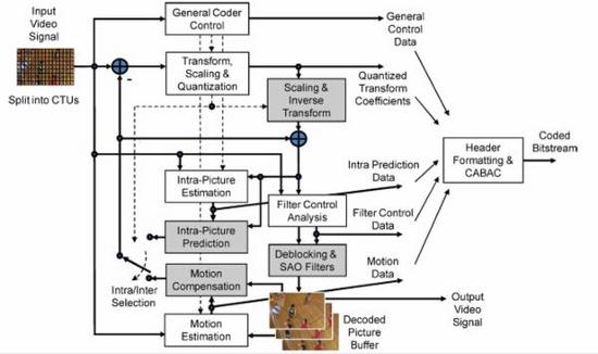
  • HEVC标准编码过程大致如下:帧首先被切分成多个块状区域,分别传输给解码器。图像序列的第一个画面(以及每一个可被拖放的帧)只使用帧内预测编码(只使用同一帧中其它区域进行预测,不依赖其他帧)。
  • 其它帧中的块大多数使用帧间预测编码,过程包括选择预测模式、参考图像的运动数据和生成每个块的运动矢量(MV)。
  • 编码器和解码器通过旁路传输预测模式信息和运动矢量(MV),计算运动补偿,进而重建帧间预测数据。
  • 帧内或帧间的预测结果和实际画面之间的残差数据经过空间-线性变换、采样、量化、熵编码后和预测信息一起传输。
  • 编码器会重复解码器的处理循环(上图中灰色方框的部分),以保证编解码双方对子序列作出一致的预测。但编码器量化的参数被解码器逆采样、逆转换还原后只能得到近似的残差。
  • 残差和预测的结果合并后会进入一或两个循环滤波器以去处块效应。最终得出的画面(解码器的输出)会存储在缓冲区中作为视频中其它图像预测参考。
  • 编解码帧序很可能会和从源下来的帧序不一样,因此对解码器来说,需要一段缓冲区来应对解码顺序(码流顺序DTS)和输出顺序(显示顺序PTS)间的差距。
  • 一般而言,HEVC编码器输入都应该是逐行扫描的(逐行源,或去交错处理后的隔行源)。HEVC的编码设计没有特意去支持隔行扫描,因为隔行扫描已经不再用于最终显示,在分发中使用隔行的场景也在大量减少。
  • 但HEVC提供了一个元数据让编码器可以声明这是一个按照场编码的隔行视频(每帧中其实只有一个场),每个画面中只有一半的信息。这样就简单而有效地降低了解码器支持隔行视频的复杂度。

HEVC混合编码特性中的要点

1) 编码树单元(CTU)和编码树块(CTB)

前代标准中的核心编码层是宏块,包含一个16×16的亮度块采样,对于一般的yuv420而言,会伴随两个8×8的色度块采样。类似结构在HEVC中被称作CTU,但它的大小是可以由编码器设定的,并且可以超越16×16。CTU由一个亮度CTB、几个色度CTB和一些关联的语法元素组成。亮度CTB的可选大小有16×16、32×32、64×64,更大的块会有更好的压缩率。HEVC还支持使用树结构和四叉树将CTB切分为更小的块。

2) 编码单元(CU)和编码块(CB)

CTU中的四叉树确定了亮度和色度CB的大小和位置,四叉树的根节点与CTU关联。亮度CB最大可以支持到亮度CTB的大小。把CTU切成亮度和色度CB的过程是一体的。一个亮度CB、两个色度CB和关联的语法元素构成一个CU。一个CTB可以只包含一个CU,也可以包含好几个CU,每一个CU都有一个分区关联的预测单元(PU)和一个变换树单元(TU)。

3) 预测单元(PU)和预测块(PB)

某帧图像采用帧内预测还是帧间预测是在CU层面决策的。PU分区结构的根也在CU层。根据预测决策的结果,亮度和色度CB进一步拆分为亮度和色度PB。HEVC支持从4×4到64×64大小的PB。

4) 变换单元(TU)和变换块(TB)

预测残差使用块变换编码。TU树结构的根在CU层面。亮度CB的残差可能和亮度TB完全一样,或者进一步切分为更小的亮度TB。色度TB也是一样的。4×4、8×8、16×16、32×32的TB都各自定义了近似DCT变换的基本整型方法。对于4×4的亮度帧内预测的残差变换,还有一个DCT变换表衍生的整型变换供选择。

5) 运动矢量

标准中采用了基于邻近PB和参考帧数据来预测方向的高级运动矢量预测(AMVP)。MV编码还可以使用一种允许继承邻近PB的MV的合并模式。此外,HEVC中还包含有一个增强版的H.264/AVC直接运动预测。

6) 运动补偿

MV使用四分之一采样预测。分级采样的插值使用7阶或8阶的滤波器(H.264/AVC中插值使用二分之一采样的6阶滤波器和四分之一采样的线性插值)。和H.264/AVC一样,HEVC也使用多参考帧。每一个PB可以根据单向或者双向预测传送一个或者两个运动矢量。同H.264/AVC一样,预测信号上可以附加采样和偏移以声明预测权重。

7) 帧内预测

不使用帧间预测时,就只能基于邻近的块来做空间上的帧内预测。HEVC的帧内预测支持33个方向模式(H.264/AVC中是8个)。HEVC还设计了增强的二维变换和可选的DC预测模式。需要由预先解码出的邻近PB计算得出最优的帧内预测模式。

8) 量化控制

和H.264/AVC一样,HEVC也使用URQ(一致量化还原)。由于HEVC引入了更多的变换块,所以量化参数矩阵也随之增多。

9) 熵编码

HEVC使用CABAC来做熵编码。和H.264/AVC中的CABAC相比,得益于新引入的并行处理架构,速度、压缩率和内存占用等方面均得到了大幅改善。

10) 内置环路滤波器

和H.264/AVC一样,HEVC的帧间预测循环中也内置去除块效应的滤波器。相比H.264/AVC,HEVC的设计更重视简化决策和滤波器的流程,并且为并行处理而优化。

11) 采样自适应偏移(SAO)

帧间预测循环的去块效应滤波器之后引入了一个非线性的幅值映射的流程。主要目的是通过编码器端的直方图分析产出一些参数以增强解码器端的幅值信号还原。

语法层面

H.264/AVC以来的语法基本得到了保留,HEVC在其基础上加入了不少为应用多样性及网络丢包而设计的特性。

1) 参数集结构

能被多个区块共享的解码信息包含在参数集中。这个结构负责保证把必不可少的解码信息传输到解码端。它由H.264/AVC中的图像序列参数集扩展而来,在HEVC中被称为VPS。

2) NAL语法单元

每个语法结构都会被放进一个叫做NAL(网络抽象层)中的逻辑上的数据包中。这个包的包头中有两个字节表明了它装载的是什么用途的数据(用于判断是否需要重传)。

3) 片

可以不依赖同帧中的其它数据独立进行预测、残差重建、熵编码的部分被称为“片”。片可以是一个帧也可以只是一个帧中的一部分。片的主要作用之一是在丢包时同步用。在包式传输中一个片可以包含的数据量是被严格限制的,在这个限制内调整片内包含的CTU数量可以有效地最小化包传输产生的额外开销。

4) 增强信息(SEI)和视频可用性信息(VUI)

SEI和VUI用于存储视频元数据,比如说时间戳、使用的色彩空间、3D填充的方式等等。

并行化设计和片的改良

最后要介绍的是HEVC中增强的并行处理架构和为包传输而改良的片结构。这两个特性可能会在某些应用中十分有用,具体实现可以考量自己的情况采用它们。
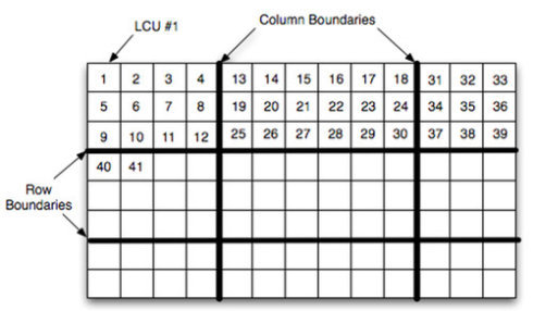
1) 并行块(Tile)

HEVC定义了一个可选的方式,可以把一帧图像分割成并行块。并行块的主要目的是在增强并行处理的能力同时又不引入新的错误扩散。并行块是一些在一帧图像内使用一些共有的信息编码而成,但可以独立解码的区域。一般的做法是将图像切割成包含大体相同数量CTU的并行块。并行块的引入使得简单粗粒度的并行化处理成为可能,线程之间将不再需要考虑复杂的同步和锁。
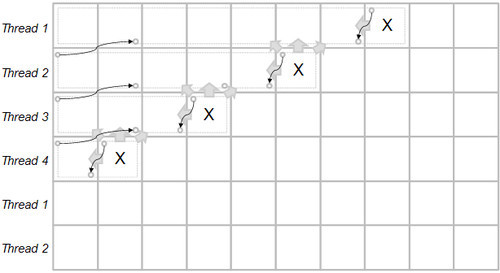
这里写图片描述

2) 错峰并行处理(WPP)

主要用于熵编码。当WPP开启时,片先被分成数个CTU行。第一行正常处理,第二行在第一行处理完2个CTU后开始处理,第三行在第二行处理完2个CTU后开始处理。每一行相对前一行都有2个CTU的延迟。WPP提供了一种在适当的层级上(比如说片)并行化的方式。WPP可以提供比并行块更好的压缩效率,而且不会引入块效应。
这里写图片描述

3) 依赖更小片(Dependent slice segments)

这个设计允许数据与错峰并行处理或者并行块关联起来,在碎片化的包传输网络中,相对于一次编码一整片而言,这种做法可以更快进入解码流程,从而降低延迟。与错峰并行处理一起使用用时,它也需要类似错峰的机制。这项设计尤为适合低延迟要求下的并行处理。

原文地址:http://www.tuicool.com/articles/32Qf6r

  • 0
    点赞
  • 0
    收藏
    觉得还不错? 一键收藏
  • 0
    评论
HEVC标准最后一版(2013年1月23日发布)! 历史: 早在2004年,ITU-T视频编码专家组(VCEG)开始研究新技术以便创建一个新的视频压缩标准。在2004年10月,H.264/ AVC小组对潜在的各种技术进行了调查。2005年1月VCEG的会议上,VCEG开始指定某些主题为“关键技术”作进一步研究。2005年成立软件代码库称为Key Technical Areas (KTA)用来评估这些新的“关键技术。KTA的软件是在联合模型(JM)基础上由MPEG和VCEG的视频组联合开发的,项目名称暂定为H.265和H.NGVC(Next-generation Video Coding),此项目在2010年最终演化为由VCEG和MPEG合资项目也叫做HEVC(High efficiency video coding)。 按照NGVC的初步要求,在维持视觉质量相同的情况下,比特率较H.264/MPEG-4 AVC的高中档(high profile),计算复杂度维持在比特率较H.264/MPEG-4 AVC的高中档的1/2至3倍之间。 “H.265” 只是作为 “高性能视频编码(HEVC)”一个昵称。2009年7月,实验结果表明比特率相较于H.264/AVC High Profile平均降低20%左右,这些结果促使MPEG与VCEG合作发起的新的标准化工作。 2010年1月,VCEG和MPEG开始发起视频压缩技术正式提案。相关技术由视频编码联合组(Joint Collaborative Team on Video Coding (JCT-VC))审议和评估,其合作小组第一次会议于2010年4月召开大会,一共有27个完整的提案。评价结果表明,一些提案在许多测试用例可以达到只用一半的比特率并维持H.264/AVC相同的视觉质量。在这次会议上,联合项目名改称为高效率的视频编码(HEVC),并且JCT-VC小组把相关技术集成到一个的软件代码库(HM[2])和标准文本草案规范,并进行进一步实验,以评估各项功能。[1] 新技术特点: HEVC草案设计,包括各种编码技术: 树状结构的预测和残差块分割 扩展预测块大小(最多为64×64) 大块变换(最大余弦变换块为32×32) 正方形和非正方形的变换块 整数逆变换 基于方向的帧内预测与预测类型 基于模式依赖正弦/余弦变换 自适应运动矢量预测选择机制 基于空间的运动矢量预测 多帧运动补偿预测 高精度运动补偿插值 去块滤波器 自适应环路滤波器(ALF) 上下文自适应进制算术编码(CABAC) 进度表 HEVC标准时间表如下: 2012年2月:委员会草案(完整的标准草案) 2012年7月:国际标准草案 2013年1月:国际标准最终草案(准备被批准为标准) 2013年1月26日,其正式成为国际标准
新一代视频压缩编码技术!今年刚认证的H.265编码标准,前几天一直找不到白皮书,今天发上来,估计不少人也在找吧。下面是目录: CONTENTS Page Abstract i 0 Introduction 1 0.1 General 1 0.2 Prologue 1 0.3 Purpose 1 0.4 Applications 1 0.5 Publication and versions of this Specification 1 0.6 Profiles, tiers and levels 2 0.7 Overview of the design characteristics 2 0.8 How to read this Specification 2 1 Scope 3 2 Normative references 3 2.1 General 3 2.2 Identical Recommendations | International Standards 3 2.3 Paired Recommendations | International Standards equivalent in technical content 3 2.4 Additional references 3 3 Definitions 3 4 Abbreviations 12 5 Conventions 13 5.1 General 13 5.2 Arithmetic operators 13 5.3 Logical operators 13 5.4 Relational operators 14 5.5 Bit-wise operators 14 5.6 Assignment operators 14 5.7 Range notation 14 5.8 Mathematical functions 15 5.9 Order of operation precedence 15 5.10 Variables, syntax elements, and tables 16 5.11 Text description of logical operations 17 5.12 Processes 18 6 Bitstream and picture formats, partitionings, scanning processes, and neighbouring relationships 18 6.1 Bitstream formats 18 6.2 Source, decoded, and output picture formats 18 6.3 Partitioning of pictures, slices, slice segments, tiles, coding tree units, and coding tree blocks 21 6.3.1 Partitioning of pictures into slices, slice segments, and tiles 21 6.3.2 Block and quadtree structures 22 6.3.3 Spatial or component-wise partionings 23 6.4 Availability processes 23 6.4.1 Derivation process for z-scan order block availability 23 6.4.2 Derivation process for prediction block availability 24 6.5 Scanning processes 25 6.5.1 Coding tree block raster and tile scanning conversion process 25 6.5.2 Z-scan order array initialization process 26 6.5.3 Up-right diagonal scan order array initialization process 26 6.5.4 Horizontal scan order array initialization process 27 6.5.5 Vertical scan order array initialization process 27 7 Syntax and semantics 28 7.1 Method of specifying syntax in tabular form 28 7.2 Specification of syntax functions and descriptors 29 7.3 Syntax in tabular form 30 7.3.1 NAL unit syntax 30 7.3.1.1 General NAL unit syntax 30 7.3.1.2 NAL unit header syntax 30 7.3.2 Raw byte sequence payloads, trailing bits, and byte alignment syntax 31 7.3.2.1 Video parameter set RBSP syntax 31 7.3.2.2 Sequence parameter set RBSP syntax 32 7.3.2.3 Picture parameter set RBSP syntax 34 7.3.2.4 Supplemental enhancement information RBSP syntax 35 7.3.2.5 Access unit delimiter RBSP syntax 35 7.3.2.6 End of sequence RBSP syntax 35 7.3.2.7 End of bitstream RBSP syntax 35 7.3.2.8 Filler data RBSP syntax 36 7.3.2.9 Slice segment layer RBSP syntax 36 7.3.2.10 RBSP slice segment trailing bits syntax 36 7.3.2.11 RBSP trailing bits syntax 36 7.3.2.12 Byte alignment syntax 36 7.3.3 Profile, tier and level syntax 37 7.3.4 Scaling list data syntax 38 7.3.5 Supplemental enhancement information message syntax 38 7.3.6 Slice segment header syntax 39 7.3.6.1 General slice segment header syntax 39 7.3.6.2 Reference picture list modification syntax 41 7.3.6.3 Weighted prediction parameters syntax 42 7.3.7 Short-term reference picture set syntax 43 7.3.8 Slice segment data syntax 43 7.3.8.1 General slice segment data syntax 43 7.3.8.2 Coding tree unit syntax 44 7.3.8.3 Sample adaptive offset syntax 45 7.3.8.4 Coding quadtree syntax 46 7.3.8.5 Coding unit syntax 47 7.3.8.6 Prediction unit syntax 49 7.3.8.7 PCM sample syntax 49 7.3.8.8 Transform tree syntax 50 7.3.8.9 Motion vector difference syntax 50 7.3.8.10 Transform unit syntax 51 7.3.8.11 Residual coding syntax 52 7.4 Semantics 54 7.4.1 General 54 7.4.2 NAL unit semantics 54 7.4.2.1 General NAL unit semantics 54 7.4.2.2 NAL unit header semantics 55 7.4.2.3 Encapsulation of an SODB within an RBSP (informative) 58 7.4.2.4 Order of NAL units and association to coded pictures, access units, and coded video sequences 59 7.4.3 Raw byte sequence payloads, trailing bits, and byte alignment semantics 62 7.4.3.1 Video parameter set RBSP semantics 62 7.4.3.2 Sequence parameter set RBSP semantics 64 7.4.3.3 Picture parameter set RBSP semantics 69 7.4.3.4 Supplemental enhancement information RBSP semantics 72 7.4.3.5 Access unit delimiter RBSP semantics 72 7.4.3.6 End of sequence RBSP semantics 72 7.4.3.7 End of bitstream RBSP semantics 72 7.4.3.8 Filler data RBSP semantics 73 7.4.3.9 Slice segment layer RBSP semantics 73 7.4.3.10 RBSP slice segment trailing bits semantics 73 7.4.3.11 RBSP trailing bits semantics 73 7.4.3.12 Byte alignment semantics 73 7.4.4 Profile, tier and level semantics 73 7.4.5 Scaling list data semantics 75 7.4.6 Supplemental enhancement information message semantics 76 7.4.7 Slice segment header semantics 77 7.4.7.1 General slice segment header semantics 77 7.4.7.2 Reference picture list modification semantics 81 7.4.7.3 Weighted prediction parameters semantics 82 7.4.8 Short-term reference picture set semantics 83 7.4.9 Slice segment data semantics 85 7.4.9.1 General slice segment data semantics 85 7.4.9.2 Coding tree unit semantics 85 7.4.9.3 Sample adaptive offset semantics 85 7.4.9.4 Coding quadtree semantics 87 7.4.9.5 Coding unit semantics 87 7.4.9.6 Prediction unit semantics 89 7.4.9.7 PCM sample semantics 90 7.4.9.8 Transform tree semantics 90 7.4.9.9 Motion vector difference semantics 91 7.4.9.10 Transform unit semantics 91 7.4.9.11 Residual coding semantics 92 8 Decoding process 94 8.1 General decoding process 94 8.2 NAL unit decoding process 95 8.3 Slice decoding process 96 8.3.1 Decoding process for picture order count 96 8.3.2 Decoding process for reference picture set 96 8.3.3 Decoding process for generating unavailable reference pictures 100 8.3.3.1 General decoding process for generating unavailable reference pictures 100 8.3.3.2 Generation of one unavailable picture 101 8.3.4 Decoding process for reference picture lists construction 101 8.4 Decoding process for coding units coded in intra prediction mode 102 8.4.1 General decoding process for coding units coded in intra prediction mode 102 8.4.2 Derivation process for luma intra prediction mode 103 8.4.3 Derivation process for chroma intra prediction mode 105 8.4.4 Decoding process for intra blocks 105 8.4.4.1 General decoding process for intra blocks 105 8.4.4.2 Intra sample prediction 106 8.5 Decoding process for coding units coded in inter prediction mode 112 8.5.1 General decoding process for coding units coded in inter prediction mode 112 8.5.2 Inter prediction process 112 8.5.3 Decoding process for prediction units in inter prediction mode 115 8.5.3.1 General 115 8.5.3.2 Derivation process for motion vector components and reference indices 115 8.5.3.3 Decoding process for inter prediction samples 130 8.5.4 Decoding process for the residual signal of coding units coded in inter prediction mode 138 8.5.4.1 General 138 8.5.4.2 Decoding process for luma residual blocks 139 8.5.4.3 Decoding process for chroma residual blocks 140 8.6 Scaling, transformation and array construction process prior to deblocking filter process 141 8.6.1 Derivation process for quantization parameters 141 8.6.2 Scaling and transformation process 142 8.6.3 Scaling process for transform coefficients 143 8.6.4 Transformation process for scaled transform coefficients 144 8.6.4.1 General 144 8.6.4.2 Transformation process 144 8.6.5 Picture construction process prior to in-loop filter process 146 8.7 In-loop filter process 146 8.7.1 General 146 8.7.2 Deblocking filter process 147 8.7.2.1 General 147 8.7.2.2 Derivation process of transform block boundary 148 8.7.2.3 Derivation process of prediction block boundary 149 8.7.2.4 Derivation process of boundary filtering strength 150 8.7.2.5 Edge filtering process 151 8.7.3 Sample adaptive offset process 159 8.7.3.1 General 159 8.7.3.2 Coding tree block modification process 159 9 Parsing process 161 9.1 General 161 9.2 Parsing process for 0-th order Exp-Golomb codes 161 9.2.1 General 161 9.2.2 Mapping process for signed Exp-Golomb codes 163 9.3 CABAC parsing process for slice segment data 163 9.3.1 General 163 9.3.2 Initialization process 165 9.3.2.1 General 165 9.3.2.2 Initialization process for context variables 166 9.3.2.3 Storage process for context variables 174 9.3.2.4 Synchronization process for context variables 174 9.3.2.5 Initialization process for the arithmetic decoding engine 174 9.3.3 Binarization process 175 9.3.3.1 General 175 9.3.3.2 Truncated Rice (TR) binarization process 176 9.3.3.3 k-th order Exp-Golomb (EGk) binarization process 177 9.3.3.4 Fixed-length (FL) binarization process 178 9.3.3.5 Binarization process for part_mode 178 9.3.3.6 Binarization process for intra_chroma_pred_mode 178 9.3.3.7 Binarization process for inter_pred_idc 179 9.3.3.8 Binarization process for cu_qp_delta_abs 179 9.3.3.9 Binarization process for coeff_abs_level_remaining 179 9.3.4 Decoding process flow 180 9.3.4.1 General 180 9.3.4.2 Derivation process for ctxTable, ctxIdx and bypassFlag 180 9.3.4.3 Arithmetic decoding process 186 9.3.5 Arithmetic encoding process (informative) 192 9.3.5.1 General 192 9.3.5.2 Initialization process for the arithmetic encoding engine (informative) 192 9.3.5.3 Encoding process for a binary decision (informative) 193 9.3.5.4 Renormalization process in the arithmetic encoding engine (informative) 194 9.3.5.5 Bypass encoding process for binary decisions (informative) 195 9.3.5.6 Encoding process for a binary decision before termination (informative) 196 9.3.5.7 Byte stuffing process (informative) 197 10 Sub-bitstream extraction process 198 Annex A Profiles, tiers and levels 199 A.1 Overview of profiles, tiers and levels 199 A.2 Requirements on video decoder capability 199 A.3 Profiles 199 A.3.1 General 199 A.3.2 Main profile 199 A.3.3 Main 10 profile 200 A.3.4 Main Still Picture profile 200 A.4 Tiers and levels 201 A.4.1 General tier and level limits 201 A.4.2 Profile-specific level limits for the Main and Main 10 profiles 202 A.4.3 Effect of level limits on picture rate for the Main and Main 10 profiles (informative) 204 Annex B Byte stream format 208 B.1 General 208 B.2 Byte stream NAL unit syntax and semantics 208 B.2.1 Byte stream NAL unit syntax 208 B.2.2 Byte stream NAL unit semantics 208 B.3 Byte stream NAL unit decoding process 209 B.4 Decoder byte-alignment recovery (informative) 209 Annex C Hypothetical reference decoder 210 C.1 General 210 C.2 Operation of coded picture buffer (CPB) 214 C.2.1 General 214 C.2.2 Timing of decoding unit arrival 214 C.2.3 Timing of decoding unit removal and decoding of decoding unit 216 C.3 Operation of the decoded picture buffer (DPB) 218 C.3.1 General 218 C.3.2 Removal of pictures from the DPB 218 C.3.3 Picture output 219 C.3.4 Current decoded picture marking and storage 220 C.4 Bitstream conformance 220 C.5 Decoder conformance 221 C.5.1 General 221 C.5.2 Operation of the output order DPB 222 C.5.2.1 General 222 C.5.2.2 Output and removal of pictures from the DPB 222 C.5.2.3 Picture decoding, marking, additional bumping, and storage 223 C.5.2.4 "Bumping" process 223 Annex D Supplemental enhancement information 225 D.1 General 225 D.2 SEI payload syntax 226 D.2.1 General SEI message syntax 226 D.2.2 Buffering period SEI message syntax 228 D.2.3 Picture timing SEI message syntax 229 D.2.4 Pan-scan rectangle SEI message syntax 229 D.2.5 Filler payload SEI message syntax 230 D.2.6 User data registered by Rec. ITU-T T.35 SEI message syntax 230 D.2.7 User data unregistered SEI message syntax 230 D.2.8 Recovery point SEI message syntax 230 D.2.9 Scene information SEI message syntax 231 D.2.10 Picture snapshot SEI message syntax 231 D.2.11 Progressive refinement segment start SEI message syntax 231 D.2.12 Progressive refinement segment end SEI message syntax 231 D.2.13 Film grain characteristics SEI message syntax 232 D.2.14 Post-filter hint SEI message syntax 232 D.2.15 Tone mapping information SEI message syntax 233 D.2.16 Frame packing arrangement SEI message syntax 234 D.2.17 Display orientation SEI message syntax 234 D.2.18 Structure of pictures information SEI message syntax 235 D.2.19 Decoded picture hash SEI message syntax 235 D.2.20 Active parameter sets SEI message syntax 235 D.2.21 Decoding unit information SEI message syntax 236 D.2.22 Temporal sub-layer zero index SEI message syntax 236 D.2.23 Scalable nesting SEI message syntax 236 D.2.24 Region refresh information SEI message syntax 237 D.2.25 Reserved SEI message syntax 237 D.3 SEI payload semantics 237 D.3.1 General SEI payload semantics 237 D.3.2 Buffering period SEI message semantics 240 D.3.3 Picture timing SEI message semantics 242 D.3.4 Pan-scan rectangle SEI message semantics 247 D.3.5 Filler payload SEI message semantics 248 D.3.6 User data registered by Rec. ITU-T T.35 SEI message semantics 248 D.3.7 User data unregistered SEI message semantics 248 D.3.8 Recovery point SEI message semantics 248 D.3.9 Scene information SEI message semantics 249 D.3.10 Picture snapshot SEI message semantics 252 D.3.11 Progressive refinement segment start SEI message semantics 252 D.3.12 Progressive refinement segment end SEI message semantics 253 D.3.13 Film grain characteristics SEI message semantics 253 D.3.14 Post-filter hint SEI message semantics 258 D.3.15 Tone mapping information SEI message semantics 259 D.3.16 Frame packing arrangement SEI message semantics 263 D.3.17 Display orientation SEI message semantics 270 D.3.18 Structure of pictures information SEI message semantics 271 D.3.19 Decoded picture hash SEI message semantics 272 D.3.20 Active parameter sets SEI message semantics 273 D.3.21 Decoding unit information SEI message semantics 273 D.3.22 Temporal sub-layer zero index SEI message semantics 275 D.3.23 Scalable nesting SEI message semantics 275 D.3.24 Region refresh information SEI message semantics 276 D.3.25 Reserved SEI message semantics 277 Annex E Video usability information 278 E.1 General 278 E.1 VUI syntax 279 E.1.1 VUI parameters syntax 279 E.1.2 HRD parameters syntax 281 E.1.3 Sub-layer HRD parameters syntax 282 E.2 VUI semantics 282 E.2.1 VUI parameters semantics 282 E.2.2 HRD parameters semantics 294 E.2.3 Sub-layer HRD parameters semantics 296 Bibliography 298

“相关推荐”对你有帮助么?

  • 非常没帮助
  • 没帮助
  • 一般
  • 有帮助
  • 非常有帮助
提交
评论
添加红包

请填写红包祝福语或标题

红包个数最小为10个

红包金额最低5元

当前余额3.43前往充值 >
需支付:10.00
成就一亿技术人!
领取后你会自动成为博主和红包主的粉丝 规则
hope_wisdom
发出的红包
实付
使用余额支付
点击重新获取
扫码支付
钱包余额 0

抵扣说明:

1.余额是钱包充值的虚拟货币,按照1:1的比例进行支付金额的抵扣。
2.余额无法直接购买下载,可以购买VIP、付费专栏及课程。

余额充值