


样例截取自linux4.1.13中,与设备树有关BeagleBone Black 的部分代码,
1、 定位GPIO控制器在处理的外围地址:

GPIO0 内存映射:

GPIO1 内存映射:

GPIO2、GPIO3 内存映射:

2、CONTROL_MODULE控制模式的寄存器位置:

3、引脚复用地址: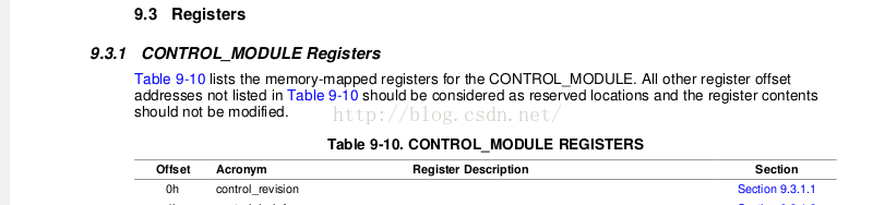

4、 Linux设备树对上述GPIO映射的实现如下:
    / {
      compatible = "ti,am33xx";
      interrupt-parent = <&intc>;

      ocp {
        compatible = "simple-bus";
        #address-cells = <1>;
        #size-cells = <1>;
        ranges;
        ti,hwmods = "l3_main";
        gpio0: gpio@44e07000 {
            compatible = "ti,omap4-gpio";
            ti,hwmods = "gpio1";
            gpio-controller;
            #gpio-cells = <2>;
            interrupt-controller;
            #interrupt-cells = <2>;
            reg = <0x44e07000 0x1000>;
            interrupts = <96>;
        };

        gpio1: gpio@4804c000 {
            compatible = "ti,omap4-gpio";
            ti,hwmods = "gpio2";
            gpio-controller;
            #gpio-cells = <2>;
            interrupt-controller;
            #interrupt-cells = <2>;
            reg = <0x4804c000 0x1000>;
            interrupts = <98>;
        };

        gpio2: gpio@481ac000 {
            compatible = "ti,omap4-gpio";
            ti,hwmods = "gpio3";
            gpio-controller;
            #gpio-cells = <2>;
            interrupt-controller;
            #interrupt-cells = <2>;
            reg = <0x481ac000 0x1000>;
            interrupts = <32>;
        };

        gpio3: gpio@481ae000 {
            compatible = "ti,omap4-gpio";
            ti,hwmods = "gpio4";
            gpio-controller;
            #gpio-cells = <2>;
            interrupt-controller;
            #interrupt-cells = <2>;
            reg = <0x481ae000 0x1000>;
            interrupts = <62>;
        };
      };
 }:
5、控制模式器和引脚复用内存映射
ocp {
        compatible = "simple-bus";
        #address-cells = <1>;
        #size-cells = <1>;
        ranges;
        ti,hwmods = "l3_main";

        l4_wkup: l4_wkup@44c00000 {
            compatible = "ti,am3-l4-wkup", "simple-bus";
            #address-cells = <1>;
            #size-cells = <1>;
            ranges = <0 0x44c00000 0x280000>;

                scm: scm@210000 {
                compatible = "ti,am3-scm", "simple-bus";
                reg = <0x210000 0x2000>;
                #address-cells = <1>;
                #size-cells = <1>;
                ranges = <0 0x210000 0x2000>;

/*

*计算下 控制模式的地址 = 0x44c00000+0x210000=0x44E1000

*引脚复用地址=0x44E1000+0x800 = 0x44E10800

*/

                am33xx_pinmux: pinmux@800 {
                    compatible = "pinctrl-single";
                    reg = <0x800 0x238>;
                    #address-cells = <1>;
                    #size-cells = <0>;
                    pinctrl-single,register-width = <32>;
                    pinctrl-single,function-mask = <0x7f>;
                };

           };

  };
6、开启处理器的内部引脚复用、上下拉等属性有关的CONTROL_MODULE:
TI的处理器有专门的控制器模式,用于设置IO属性。处理器的部分引脚有复用功能,必须记得设置引脚复用单元,此处开启的是beaglebone black上的4个usr led,其详细的引脚位置不贴出了,请查阅相关手册。
&am33xx_pinmux {
    pinctrl-names = "default";
    pinctrl-0 = <&clkout2_pin>;

    user_leds_s0: user_leds_s0 {
        pinctrl-single,pins = <
            0x54 (PIN_OUTPUT_PULLDOWN | MUX_MODE7)    /* gpmc_a5.gpio1_21 */
            0x58 (PIN_OUTPUT_PULLUP | MUX_MODE7)    /* gpmc_a6.gpio1_22 */
            0x5c (PIN_OUTPUT_PULLDOWN | MUX_MODE7)    /* gpmc_a7.gpio1_23 */
            0x60 (PIN_OUTPUT_PULLUP | MUX_MODE7)    /* gpmc_a8.gpio1_24 */
     >;
   }

}
7、linux内核与驱动LED有关的设备树实现:
/{

leds {
        pinctrl-names = "default";
        pinctrl-0 = <&user_leds_s0>;

        compatible = "gpio-leds";

        led@2 {
            label = "beaglebone:green:heartbeat";
            gpios = <&gpio1 21 GPIO_ACTIVE_HIGH>;
            linux,default-trigger = "heartbeat";
            default-state = "off";
        };

        led@3 {
            label = "beaglebone:green:mmc0";
            gpios = <&gpio1 22 GPIO_ACTIVE_HIGH>;
            linux,default-trigger = "mmc0";
            default-state = "off";
        };

        led@4 {
            label = "beaglebone:green:usr2";
            gpios = <&gpio1 23 GPIO_ACTIVE_HIGH>;
            linux,default-trigger = "cpu0";
            default-state = "off";
        };

        led@5 {
            label = "beaglebone:green:usr3";
            gpios = <&gpio1 24 GPIO_ACTIVE_HIGH>;
            linux,default-trigger = "mmc1";
            default-state = "off";
        };

}
8、 TI处理器有关的linux内核对有关的gpio、pinctrl-single、gpio-leds的设备树属性定义的描述:
8.1 ti, omap2-gpio 属性描述,摘自内核的目录下的/Documentation/devicetree/bindings/gpio/gpio-omap.txt
OMAP GPIO controller bindings

Required properties:
- compatible:
  - "ti,omap2-gpio" for OMAP2 controllers
  - "ti,omap3-gpio" for OMAP3 controllers
  - "ti,omap4-gpio" for OMAP4 controllers
- gpio-controller : Marks the device node as a GPIO controller.
- #gpio-cells : Should be two.
  - first cell is the pin number
  - second cell is used to specify optional parameters (unused)
- interrupt-controller: Mark the device node as an interrupt controller.
- #interrupt-cells : Should be 2.
  The first cell is the GPIO number.
  The second cell is used to specify flags:
    bits[3:0] trigger type and level flags:
      1 = low-to-high edge triggered.
      2 = high-to-low edge triggered.
      4 = active high level-sensitive.
      8 = active low level-sensitive.

OMAP specific properties:
- ti,hwmods:        Name of the hwmod associated to the GPIO:
            "gpio<X>", <X> being the 1-based instance number
            from the HW spec.
- ti,gpio-always-on:     Indicates if a GPIO bank is always powered and
            so will never lose its logic state.


Example:

gpio4: gpio4 {
    compatible = "ti,omap4-gpio";
    ti,hwmods = "gpio4";
    gpio-controller;
    #gpio-cells = <2>;
    interrupt-controller;
    #interrupt-cells = <2>;
};
8.2 pinctrl-single,摘自内核的目录下的/Documentation/devicetree/bindings/pinctrl/pinctrl-single.txt
One-register-per-pin type device tree based pinctrl driver

Required properties:
- compatible : "pinctrl-single" or "pinconf-single".
  "pinctrl-single" means that pinconf isn't supported.
  "pinconf-single" means that generic pinconf is supported.

- reg : offset and length of the register set for the mux registers

- pinctrl-single,register-width : pinmux register access width in bits

- pinctrl-single,function-mask : mask of allowed pinmux function bits
  in the pinmux register

Optional properties:
- pinctrl-single,function-off : function off mode for disabled state if
  available and same for all registers; if not specified, disabling of
  pin functions is ignored

- pinctrl-single,bit-per-mux : boolean to indicate that one register controls
  more than one pin, for which "pinctrl-single,function-mask" property specifies
 position mask of pin.

- pinctrl-single,drive-strength : array of value that are used to configure
  drive strength in the pinmux register. They're value of drive strength
  current and drive strength mask.

		/* drive strength current, mask */
		pinctrl-single,power-source = <0x30 0xf0>;

- pinctrl-single,bias-pullup : array of value that are used to configure the
  input bias pullup in the pinmux register.

		/* input, enabled pullup bits, disabled pullup bits, mask */
		pinctrl-single,bias-pullup = <0 1 0 1>;

- pinctrl-single,bias-pulldown : array of value that are used to configure the
  input bias pulldown in the pinmux register.

		/* input, enabled pulldown bits, disabled pulldown bits, mask */
		pinctrl-single,bias-pulldown = <2 2 0 2>;

  * Two bits to control input bias pullup and pulldown: User should use
    pinctrl-single,bias-pullup & pinctrl-single,bias-pulldown. One bit means
    pullup, and the other one bit means pulldown.
  * Three bits to control input bias enable, pullup and pulldown. User should
    use pinctrl-single,bias-pullup & pinctrl-single,bias-pulldown. Input bias
    enable bit should be included in pullup or pulldown bits.
  * Although driver could set PIN_CONFIG_BIAS_DISABLE, there's no property as
    pinctrl-single,bias-disable. Because pinctrl single driver could implement
    it by calling pulldown, pullup disabled.

- pinctrl-single,input-schmitt : array of value that are used to configure
  input schmitt in the pinmux register. In some silicons, there're two input
  schmitt value (rising-edge & falling-edge) in the pinmux register.

		/* input schmitt value, mask */
		pinctrl-single,input-schmitt = <0x30 0x70>;

- pinctrl-single,input-schmitt-enable : array of value that are used to
  configure input schmitt enable or disable in the pinmux register.

		/* input, enable bits, disable bits, mask */
		pinctrl-single,input-schmitt-enable = <0x30 0x40 0 0x70>;

- pinctrl-single,low-power-mode : array of value that are used to configure
  low power mode of this pin. For some silicons, the low power mode will
  control the output of the pin when the pad including the pin enter low
  power mode.
		/* low power mode value, mask */
		pinctrl-single,low-power-mode = <0x288 0x388>;

- pinctrl-single,gpio-range : list of value that are used to configure a GPIO
  range. They're value of subnode phandle, pin base in pinctrl device, pin
  number in this range, GPIO function value of this GPIO range.
  The number of parameters is depend on #pinctrl-single,gpio-range-cells
  property.

		/* pin base, nr pins & gpio function */
		pinctrl-single,gpio-range = <&range 0 3 0 &range 3 9 1>;

- interrupt-controller : standard interrupt controller binding if using
  interrupts for wake-up events for example. In this case pinctrl-single
  is set up as a chained interrupt controller and the wake-up interrupts
  can be requested by the drivers using request_irq().

- #interrupt-cells : standard interrupt binding if using interrupts

This driver assumes that there is only one register for each pin (unless the
pinctrl-single,bit-per-mux is set), and uses the common pinctrl bindings as
specified in the pinctrl-bindings.txt document in this directory.

The pin configuration nodes for pinctrl-single are specified as pinctrl
register offset and value pairs using pinctrl-single,pins. Only the bits
specified in pinctrl-single,function-mask are updated. For example, setting
a pin for a device could be done with:

	pinctrl-single,pins = <0xdc 0x118>;

Where 0xdc is the offset from the pinctrl register base address for the
device pinctrl register, and 0x118 contains the desired value of the
pinctrl register. See the device example and static board pins example
below for more information.

In case when one register changes more than one pin's mux the
pinctrl-single,bits need to be used which takes three parameters:

	pinctrl-single,bits = <0xdc 0x18 0xff>;

Where 0xdc is the offset from the pinctrl register base address for the
device pinctrl register, 0x18 is the desired value, and 0xff is the sub mask to
be used when applying this change to the register.


Optional sub-node: In case some pins could be configured as GPIO in the pinmux
register, those pins could be defined as a GPIO range. This sub-node is required
by pinctrl-single,gpio-range property.

Required properties in sub-node:
- #pinctrl-single,gpio-range-cells : the number of parameters after phandle in
  pinctrl-single,gpio-range property.

	range: gpio-range {
		#pinctrl-single,gpio-range-cells = <3>;
	};


Example:

/* SoC common file */

/* first controller instance for pins in core domain */
pmx_core: pinmux@4a100040 {
	compatible = "pinctrl-single";
	reg = <0x4a100040 0x0196>;
	#address-cells = <1>;
	#size-cells = <0>;
	#interrupt-cells = <1>;
	interrupt-controller;
	pinctrl-single,register-width = <16>;
	pinctrl-single,function-mask = <0xffff>;
};

/* second controller instance for pins in wkup domain */
pmx_wkup: pinmux@4a31e040 {
	compatible = "pinctrl-single";
	reg = <0x4a31e040 0x0038>;
	#address-cells = <1>;
	#size-cells = <0>;
	#interrupt-cells = <1>;
	interrupt-controller;
	pinctrl-single,register-width = <16>;
	pinctrl-single,function-mask = <0xffff>;
};

control_devconf0: pinmux@48002274 {
	compatible = "pinctrl-single";
	reg = <0x48002274 4>;	/* Single register */
	#address-cells = <1>;
	#size-cells = <0>;
	pinctrl-single,bit-per-mux;
	pinctrl-single,register-width = <32>;
	pinctrl-single,function-mask = <0x5F>;
};

/* third controller instance for pins in gpio domain */
pmx_gpio: pinmux@d401e000 {
	compatible = "pinconf-single";
	reg = <0xd401e000 0x0330>;
	#address-cells = <1>;
	#size-cells = <1>;
	ranges;

	pinctrl-single,register-width = <32>;
	pinctrl-single,function-mask = <7>;

	/* sparse GPIO range could be supported */
	pinctrl-single,gpio-range = <&range 0 3 0 &range 3 9 1
				&range 12 1 0 &range 13 29 1
				&range 43 1 0 &range 44 49 1
				&range 94 1 1 &range 96 2 1>;

	range: gpio-range {
		#pinctrl-single,gpio-range-cells = <3>;
	};
};


/* board specific .dts file */

&pmx_core {

	/*
	 * map all board specific static pins enabled by the pinctrl driver
	 * itself during the boot (or just set them up in the bootloader)
	 */
	pinctrl-names = "default";
	pinctrl-0 = <&board_pins>;

	board_pins: pinmux_board_pins {
		pinctrl-single,pins = <
			0x6c 0xf
			0x6e 0xf
			0x70 0xf
			0x72 0xf
		>;
	};

	uart0_pins: pinmux_uart0_pins {
		pinctrl-single,pins = <
			0x208 0		/* UART0_RXD (IOCFG138) */
			0x20c 0		/* UART0_TXD (IOCFG139) */
		>;
		pinctrl-single,bias-pulldown = <0 2 2>;
		pinctrl-single,bias-pullup = <0 1 1>;
	};

	/* map uart2 pins */
	uart2_pins: pinmux_uart2_pins {
		pinctrl-single,pins = <
			0xd8 0x118
			0xda 0
			0xdc 0x118
			0xde 0
		>;
	};
};

&control_devconf0 {
	mcbsp1_pins: pinmux_mcbsp1_pins {
		pinctrl-single,bits = <
			0x00 0x18 0x18 /* FSR/CLKR signal from FSX/CLKX pin */
		>;
	};

	mcbsp2_clks_pins: pinmux_mcbsp2_clks_pins {
		pinctrl-single,bits = <
			0x00 0x40 0x40 /* McBSP2 CLKS from McBSP_CLKS pin */
		>;
	};

};

&uart1 {
       pinctrl-names = "default";
       pinctrl-0 = <&uart0_pins>;
};

&uart2 {
       pinctrl-names = "default";
       pinctrl-0 = <&uart2_pins>;
};
8.3 gpio-leds,摘自内核的目录下的/Documentation/devicetree/bindings/leds/txtleds-gpio.txt
LEDs connected to GPIO lines

Required properties:
- compatible : should be "gpio-leds".

Each LED is represented as a sub-node of the gpio-leds device.  Each
node's name represents the name of the corresponding LED.

LED sub-node properties:
- gpios :  Should specify the LED's GPIO, see "gpios property" in
  Documentation/devicetree/bindings/gpio/gpio.txt.  Active low LEDs should be
  indicated using flags in the GPIO specifier.
- label :  (optional)
  see Documentation/devicetree/bindings/leds/common.txt
- linux,default-trigger :  (optional)
  see Documentation/devicetree/bindings/leds/common.txt
- default-state:  (optional) The initial state of the LED.  Valid
  values are "on", "off", and "keep".  If the LED is already on or off
  and the default-state property is set the to same value, then no
  glitch should be produced where the LED momentarily turns off (or
  on).  The "keep" setting will keep the LED at whatever its current
  state is, without producing a glitch.  The default is off if this
  property is not present.
- retain-state-suspended: (optional) The suspend state can be retained.Such
  as charge-led gpio.

Examples:

#include <dt-bindings/gpio/gpio.h>

leds {
    compatible = "gpio-leds";
    hdd {
        label = "IDE Activity";
        gpios = <&mcu_pio 0 GPIO_ACTIVE_LOW>;
        linux,default-trigger = "ide-disk";
    };

    fault {
        gpios = <&mcu_pio 1 GPIO_ACTIVE_HIGH>;
        /* Keep LED on if BIOS detected hardware fault */
        default-state = "keep";
    };
};

run-control {
    compatible = "gpio-leds";
    red {
        gpios = <&mpc8572 6 GPIO_ACTIVE_HIGH>;
        default-state = "off";
    };
    green {
        gpios = <&mpc8572 7 GPIO_ACTIVE_HIGH>;
        default-state = "on";
    };
};

leds {
    compatible = "gpio-leds";

    charger-led {
        gpios = <&gpio1 2 GPIO_ACTIVE_HIGH>;
        linux,default-trigger = "max8903-charger-charging";
        retain-state-suspended;
    };
};
Documentation/devicetree/bindings/leds/common.txt
Common leds properties.

LED and flash LED devices provide the same basic functionality as current
regulators, but extended with LED and flash LED specific features like
blinking patterns, flash timeout, flash faults and external flash strobe mode.

Many LED devices expose more than one current output that can be connected
to one or more discrete LED component. Since the arrangement of connections
can influence the way of the LED device initialization, the LED components
have to be tightly coupled with the LED device binding. They are represented
by child nodes of the parent LED device binding.

Optional properties for child nodes:
- led-sources : List of device current outputs the LED is connected to. The
        outputs are identified by the numbers that must be defined
        in the LED device binding documentation.
- label : The label for this LED. If omitted, the label is taken from the node
      name (excluding the unit address). It has to uniquely identify
      a device, i.e. no other LED class device can be assigned the same
      label.

- linux,default-trigger :  This parameter, if present, is a
    string defining the trigger assigned to the LED.  Current triggers are:
     "backlight" - LED will act as a back-light, controlled by the framebuffer
           system
     "default-on" - LED will turn on (but for leds-gpio see "default-state"
            property in Documentation/devicetree/bindings/gpio/led.txt)
     "heartbeat" - LED "double" flashes at a load average based rate
     "ide-disk" - LED indicates disk activity
     "timer" - LED flashes at a fixed, configurable rate

- max-microamp : maximum intensity in microamperes of the LED
         (torch LED for flash devices)
- flash-max-microamp : maximum intensity in microamperes of the
                       flash LED; it is mandatory if the LED should
               support the flash mode
- flash-timeout-us : timeout in microseconds after which the flash
                     LED is turned off


Examples:

system-status {
    label = "Status";
    linux,default-trigger = "heartbeat";
    ...
};

camera-flash {
    label = "Flash";
    led-sources = <0>, <1>;
    max-microamp = <50000>;
    flash-max-microamp = <320000>;
    flash-timeout-us = <500000>;
};
9.总结:
开发一个led的驱动,实质涉及就两大块:其一就是硬件底层有关的实现,其二就是调用硬件底层来实现用户功能(低级用户功能)。
本例在硬件底层中,涉及的主要是gpio控制、控制模式的引脚复用,而要使她们能正常工作,又需要加载相应的驱动模块,而设备树的“compatible”为其找寻相应的驱动提供了路径,
led用户层的功能的驱动就要劳驾“gpio-leds” --compatible 属性来实现。
参考:
1、AM335x ARM ® CortexTM-A8 Microprocessors (MPUs) Technical Reference Manual
2、 linux4.1.13
备注:
1。 20160206, wiwa 完成初稿


 738
738


 被折叠的 条评论
为什么被折叠?
被折叠的 条评论
为什么被折叠?
 到【灌水乐园】发言


