


 本文档提供了一个32位x86汇编语言编程的基础指南,涵盖了常用指令集和调用约定等内容,适合初学者入门。
http://www.cs.virginia.edu/~evans/cs216/guides/x86.html
| University of Virginia Computer Science CS216: Program and Data Representation, Spring 2006 | 27 July 2016 |
x86 Assembly Guide
Contents: Registers | Memory and Addressing | Instructions | Calling Convention
This guide describes the basics of 32-bit x86 assembly language programming, covering a small but useful subset of the available instructions and assembler directives. There are several different assembly languages for generating x86 machine code. The one we will use in CS216 is the Microsoft Macro Assembler (MASM) assembler. MASM uses the standard Intel syntax for writing x86 assembly code.
The full x86 instruction set is large and complex (Intel's x86 instruction set manuals comprise over 2900 pages), and we do not cover it all in this guide. For example, there is a 16-bit subset of the x86 instruction set. Using the 16-bit programming model can be quite complex. It has a segmented memory model, more restrictions on register usage, and so on. In this guide, we will limit our attention to more modern aspects of x86 programming, and delve into the instruction set only in enough detail to get a basic feel for x86 programming.
Resources
- Guide to Using Assembly in Visual Studio — a tutorial on building and debugging assembly code in Visual Studio
- Intel x86 Instruction Set Reference
- Intel's Pentium Manuals (the full gory details)
Registers
Modern (i.e 386 and beyond) x86 processors have eight 32-bit general purpose registers, as depicted in Figure 1. The register names are mostly historical. For example, EAX used to be called the accumulator since it was used by a number of arithmetic operations, and ECX was known as the counter since it was used to hold a loop index. Whereas most of the registers have lost their special purposes in the modern instruction set, by convention, two are reserved for special purposes — the stack pointer (ESP) and the base pointer (EBP).
For the EAX, EBX, ECX, and EDX registers, subsections may be used. For example, the least significant 2 bytes of EAX can be treated as a 16-bit register called AX. The least significant byte of AX can be used as a single 8-bit register called AL, while the most significant byte of AX can be used as a single 8-bit register called AH. These names refer to the same physical register. When a two-byte quantity is placed into DX, the update affects the value of DH, DL, and EDX. These sub-registers are mainly hold-overs from older, 16-bit versions of the instruction set. However, they are sometimes convenient when dealing with data that are smaller than 32-bits (e.g. 1-byte ASCII characters).
When referring to registers in assembly language, the names are not case-sensitive. For example, the names EAX and eax refer to the same register.
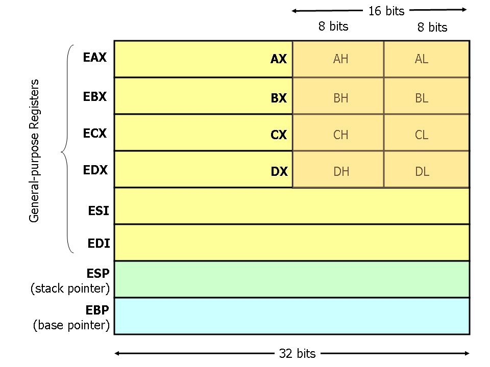
Figure 1. x86 Registers
Memory and Addressing Modes
Declaring Static Data Regions
You can declare static data regions (analogous to global variables) in x86 assembly using special assembler directives for this purpose. Data declarations should be preceded by the .DATA directive. Following this directive, the directives DB , DW , and DD can be used to declare one, two, and four byte data locations, respectively. Declared locations can be labeled with names for later reference — this is similar to declaring variables by name, but abides by some lower level rules. For example, locations declared in sequence will be located in memory next to one another.Example declarations:
.DATA var DB 64 ; Declare a byte, referred to as location var, containing the value 64. var2 DB ? ; Declare an uninitialized byte, referred to as location var2. DB 10 ; Declare a byte with no label, containing the value 10. Its location is var2 + 1. X DW ? ; Declare a 2-byte uninitialized value, referred to as location X. Y DD 30000 ; Declare a 4-byte value, referred to as location Y, initialized to 30000.
Unlike in high level languages where arrays can have many dimensions and are accessed by indices, arrays in x86 assembly language are simply a number of cells located contiguously in memory. An array can be declared by just listing the values, as in the first example below. Two other common methods used for declaring arrays of data are the DUP directive and the use of string literals. The DUP directive tells the assembler to duplicate an expression a given number of times. For example, 4 DUP(2) is equivalent to 2, 2, 2, 2.
Some examples:
Z DD 1, 2, 3 ; Declare three 4-byte values, initialized to 1, 2, and 3. The value of location Z + 8 will be 3. bytes DB 10 DUP(?) ; Declare 10 uninitialized bytes starting at location bytes. arr DD 100 DUP(0) ; Declare 100 4-byte words starting at location arr, all initialized to 0 str DB 'hello',0 ; Declare 6 bytes starting at the address str, initialized to the ASCII character values for hello and the null (0) byte.
Addressing Memory
Modern x86-compatible processors are capable of addressing up to 2 32 bytes of memory: memory addresses are 32-bits wide. In the examples above, where we used labels to refer to memory regions, these labels are actually replaced by the assembler with 32-bit quantities that specify addresses in memory. In addition to supporting referring to memory regions by labels (i.e. constant values), the x86 provides a flexible scheme for computing and referring to memory addresses: up to two of the 32-bit registers and a 32-bit signed constant can be added together to compute a memory address. One of the registers can be optionally pre-multiplied by 2, 4, or 8. The addressing modes can be used with many x86 instructions (we'll describe them in the next section). Here we illustrate some examples using the mov instruction that moves data between registers and memory. This instruction has two operands: the first is the destination and the second specifies the source. Some examples of mov instructions using address computations are:Some examples of invalid address calculations include:
mov eax, [ebx] ; Move the 4 bytes in memory at the address contained in EBX into EAX mov [var], ebx ; Move the contents of EBX into the 4 bytes at memory address var. (Note, var is a 32-bit constant). mov eax, [esi-4] ; Move 4 bytes at memory address ESI + (-4) into EAX mov [esi+eax], cl ; Move the contents of CL into the byte at address ESI+EAX mov edx, [esi+4*ebx] ; Move the 4 bytes of data at address ESI+4*EBX into EDX
mov eax, [ebx-ecx] ; Can only add register values mov [eax+esi+edi], ebx ; At most 2 registers in address computation
Size Directives
In general, the intended size of the of the data item at a given memory address can be inferred from the assembly code instruction in which it is referenced. For example, in all of the above instructions, the size of the memory regions could be inferred from the size of the register operand. When we were loading a 32-bit register, the assembler could infer that the region of memory we were referring to was 4 bytes wide. When we were storing the value of a one byte register to memory, the assembler could infer that we wanted the address to refer to a single byte in memory. However, in some cases the size of a referred-to memory region is ambiguous. Consider the instruction mov [ebx], 2 . Should this instruction move the value 2 into the single byte at address EBX ? Perhaps it should move the 32-bit integer representation of 2 into the 4-bytes starting at address EBX . Since either is a valid possible interpretation, the assembler must be explicitly directed as to which is correct. The size directives BYTE PTR , WORD PTR , and DWORD PTR serve this purpose, indicating sizes of 1, 2, and 4 bytes respectively. For example:
mov BYTE PTR [ebx], 2 ; Move 2 into the single byte at the address stored in EBX. mov WORD PTR [ebx], 2 ; Move the 16-bit integer representation of 2 into the 2 bytes starting at the address in EBX. mov DWORD PTR [ebx], 2 ; Move the 32-bit integer representation of 2 into the 4 bytes starting at the address in EBX.
Instructions
Machine instructions generally fall into three categories: data movement, arithmetic/logic, and control-flow. In this section, we will look at important examples of x86 instructions from each category. This section should not be considered an exhaustive list of x86 instructions, but rather a useful subset. For a complete list, see Intel's instruction set reference. We use the following notation:
<reg32> Any 32-bit register (EAX, EBX, ECX, EDX, ESI, EDI, ESP, or EBP) <reg16> Any 16-bit register (AX, BX, CX, or DX) <reg8> Any 8-bit register (AH, BH, CH, DH, AL, BL, CL, or DL) <reg> Any register <mem> A memory address (e.g., [eax], [var + 4], or dword ptr [eax+ebx]) <con32> Any 32-bit constant <con16> Any 16-bit constant <con8> Any 8-bit constant <con> Any 8-, 16-, or 32-bit constant
Data Movement Instructions
mov — Move (Opcodes: 88, 89, 8A, 8B, 8C, 8E, ...)The mov instruction copies the data item referred to by its second operand (i.e. register contents, memory contents, or a constant value) into the location referred to by its first operand (i.e. a register or memory). While register-to-register moves are possible, direct memory-to-memory moves are not. In cases where memory transfers are desired, the source memory contents must first be loaded into a register, then can be stored to the destination memory address.Syntax
mov <reg>,<reg>
mov <reg>,<mem>
mov <mem>,<reg>
mov <reg>,<const>
mov <mem>,<const>
Examples
mov eax, ebx — copy the value in ebx into eax
mov byte ptr [var], 5 — store the value 5 into the byte at location var
push — Push stack (Opcodes: FF, 89, 8A, 8B, 8C, 8E, ...)
The push instruction places its operand onto the top of the hardware supported stack in memory. Specifically, push first decrements ESP by 4, then places its operand into the contents of the 32-bit location at address [ESP]. ESP (the stack pointer) is decremented by push since the x86 stack grows down - i.e. the stack grows from high addresses to lower addresses. Syntaxpop — Pop stack
push <reg32>
push <mem>
push <con32>Examples
push eax — push eax on the stack
push [var] — push the 4 bytes at address var onto the stack
The pop instruction removes the 4-byte data element from the top of the hardware-supported stack into the specified operand (i.e. register or memory location). It first moves the 4 bytes located at memory location [SP] into the specified register or memory location, and then increments SP by 4.lea — Load effective addressSyntax
Examples
pop <reg32>
pop <mem>
pop edi — pop the top element of the stack into EDI.
pop [ebx] — pop the top element of the stack into memory at the four bytes starting at location EBX.
The lea instruction places the address specified by its second operand into the register specified by its first operand. Note, the contents of the memory location are not loaded, only the effective address is computed and placed into the register. This is useful for obtaining a pointer into a memory region.Syntax
lea <reg32>,<mem>Examples
lea edi, [ebx+4*esi] — the quantity EBX+4*ESI is placed in EDI.
lea eax, [var] — the value in var is placed in EAX.
lea eax, [val] — the value val is placed in EAX.
Arithmetic and Logic Instructions
add — Integer AdditionThe add instruction adds together its two operands, storing the result in its first operand. Note, whereas both operands may be registers, at most one operand may be a memory location. Syntaxsub — Integer Subtraction
add <reg>,<reg>
add <reg>,<mem>
add <mem>,<reg>
add <reg>,<con>
add <mem>,<con>
Examples
add eax, 10 — EAX ← EAX + 10
add BYTE PTR [var], 10 — add 10 to the single byte stored at memory address var
The sub instruction stores in the value of its first operand the result of subtracting the value of its second operand from the value of its first operand. As with add Syntaxinc, dec — Increment, Decrement
sub <reg>,<reg>
sub <reg>,<mem>
sub <mem>,<reg>
sub <reg>,<con>
sub <mem>,<con>
Examples
sub al, ah — AL ← AL - AH
sub eax, 216 — subtract 216 from the value stored in EAX
The inc instruction increments the contents of its operand by one. The dec instruction decrements the contents of its operand by one.imul — Integer MultiplicationSyntax
inc <reg>
inc <mem>
dec <reg>
dec <mem>Examples
dec eax — subtract one from the contents of EAX.
inc DWORD PTR [var] — add one to the 32-bit integer stored at location var
The imul instruction has two basic formats: two-operand (first two syntax listings above) and three-operand (last two syntax listings above). The two-operand form multiplies its two operands together and stores the result in the first operand. The result (i.e. first) operand must be a register. The three operand form multiplies its second and third operands together and stores the result in its first operand. Again, the result operand must be a register. Furthermore, the third operand is restricted to being a constant value. Syntaxidiv — Integer Division
imul <reg32>,<reg32>
imul <reg32>,<mem>
imul <reg32>,<reg32>,<con>
imul <reg32>,<mem>,<con>Examples
imul eax, [var] — multiply the contents of EAX by the 32-bit contents of the memory location var. Store the result in EAX.imul esi, edi, 25 — ESI → EDI * 25
The idiv instruction divides the contents of the 64 bit integer EDX:EAX (constructed by viewing EDX as the most significant four bytes and EAX as the least significant four bytes) by the specified operand value. The quotient result of the division is stored into EAX, while the remainder is placed in EDX.and, or, xor — Bitwise logical and, or and exclusive orSyntax
idiv <reg32>
idiv <mem>Examples
idiv ebx — divide the contents of EDX:EAX by the contents of EBX. Place the quotient in EAX and the remainder in EDX.idiv DWORD PTR [var] — divide the contents of EDX:EAS by the 32-bit value stored at memory location var. Place the quotient in EAX and the remainder in EDX.
These instructions perform the specified logical operation (logical bitwise and, or, and exclusive or, respectively) on their operands, placing the result in the first operand location.not — Bitwise Logical NotSyntax
and <reg>,<reg>
and <reg>,<mem>
and <mem>,<reg>
and <reg>,<con>
and <mem>,<con>
or <reg>,<reg>
or <reg>,<mem>
or <mem>,<reg>
or <reg>,<con>
or <mem>,<con>
xor <reg>,<reg>
xor <reg>,<mem>
xor <mem>,<reg>
xor <reg>,<con>
xor <mem>,<con>
Examples
and eax, 0fH — clear all but the last 4 bits of EAX.
xor edx, edx — set the contents of EDX to zero.
Logically negates the operand contents (that is, flips all bit values in the operand).Syntax
not <reg>
not <mem>Example
not BYTE PTR [var] — negate all bits in the byte at the memory location var.
neg — Negate
Performs the two's complement negation of the operand contents.shl, shr — Shift Left, Shift RightSyntax
neg <reg>
neg <mem>Example
neg eax — EAX → - EAX
These instructions shift the bits in their first operand's contents left and right, padding the resulting empty bit positions with zeros. The shifted operand can be shifted up to 31 places. The number of bits to shift is specified by the second operand, which can be either an 8-bit constant or the register CL. In either case, shifts counts of greater then 31 are performed modulo 32.Syntax
shl <reg>,<con8>
shl <mem>,<con8>
shl <reg>,<cl>
shl <mem>,<cl>shr <reg>,<con8>
shr <mem>,<con8>
shr <reg>,<cl>
shr <mem>,<cl>Examples
shl eax, 1 — Multiply the value of EAX by 2 (if the most significant bit is 0)shr ebx, cl — Store in EBX the floor of result of dividing the value of EBX by 2 n where n is the value in CL.
Control Flow Instructions
The x86 processor maintains an instruction pointer (IP) register that is a 32-bit value indicating the location in memory where the current instruction starts. Normally, it increments to point to the next instruction in memory begins after execution an instruction. The IP register cannot be manipulated directly, but is updated implicitly by provided control flow instructions.We use the notation <label> to refer to labeled locations in the program text. Labels can be inserted anywhere in x86 assembly code text by entering a label name followed by a colon. For example,
       mov esi, [ebp+8]
begin: xor ecx, ecx
       mov eax, [esi]
The second instruction in this code fragment is labeled
begin
. Elsewhere in the code, we can refer to the memory location that this instruction is located at in memory using the more convenient symbolic name
begin
. This label is just a convenient way of expressing the location instead of its 32-bit value.
jmp — Jump
Transfers program control flow to the instruction at the memory location indicated by the operand.jcondition — Conditional JumpSyntax
jmp <label>Example
jmp begin — Jump to the instruction labeled begin.
These instructions are conditional jumps that are based on the status of a set of condition codes that are stored in a special register called the machine status word. The contents of the machine status word include information about the last arithmetic operation performed. For example, one bit of this word indicates if the last result was zero. Another indicates if the last result was negative. Based on these condition codes, a number of conditional jumps can be performed. For example, the jz instruction performs a jump to the specified operand label if the result of the last arithmetic operation was zero. Otherwise, control proceeds to the next instruction in sequence.cmp — CompareA number of the conditional branches are given names that are intuitively based on the last operation performed being a special compare instruction, cmp (see below). For example, conditional branches such as jle and jne are based on first performing a cmp operation on the desired operands.
Syntax
je <label> (jump when equal)
jne <label> (jump when not equal)
jz <label> (jump when last result was zero)
jg <label> (jump when greater than)
jge <label> (jump when greater than or equal to)
jl <label> (jump when less than)
jle <label> (jump when less than or equal to)Example
cmp eax, ebx
jle doneIf the contents of EAX are less than or equal to the contents of EBX, jump to the label done. Otherwise, continue to the next instruction.
Compare the values of the two specified operands, setting the condition codes in the machine status word appropriately. This instruction is equivalent to the sub instruction, except the result of the subtraction is discarded instead of replacing the first operand.call, ret — Subroutine call and returnSyntax
cmp <reg>,<reg>
cmp <reg>,<mem>
cmp <mem>,<reg>
cmp <reg>,<con>Example
cmp DWORD PTR [var], 10
jeq loopIf the 4 bytes stored at location var are equal to the 4-byte integer constant 10, jump to the location labeled loop.
These instructions implement a subroutine call and return. The call instruction first pushes the current code location onto the hardware supported stack in memory (see the push instruction for details), and then performs an unconditional jump to the code location indicated by the label operand. Unlike the simple jump instructions, the call instruction saves the location to return to when the subroutine completes.The ret instruction implements a subroutine return mechanism. This instruction first pops a code location off the hardware supported in-memory stack (see the pop instruction for details). It then performs an unconditional jump to the retrieved code location.
Syntax
call <label>
ret
Calling Convention
To allow separate programmers to share code and develop libraries for use by many programs, and to simplify the use of subroutines in general, programmers typically adopt a common calling convention . The calling convention is a protocol about how to call and return from routines. For example, given a set of calling convention rules, a programmer need not examine the definition of a subroutine to determine how parameters should be passed to that subroutine. Furthermore, given a set of calling convention rules, high-level language compilers can be made to follow the rules, thus allowing hand-coded assembly language routines and high-level language routines to call one another. In practice, many calling conventions are possible. We will use the widely used C language calling convention. Following this convention will allow you to write assembly language subroutines that are safely callable from C (and C++) code, and will also enable you to call C library functions from your assembly language code. The C calling convention is based heavily on the use of the hardware-supported stack. It is based on the push , pop , call , and ret instructions. Subroutine parameters are passed on the stack. Registers are saved on the stack, and local variables used by subroutines are placed in memory on the stack. The vast majority of high-level procedural languages implemented on most processors have used similar calling conventions. The calling convention is broken into two sets of rules. The first set of rules is employed by the caller of the subroutine, and the second set of rules is observed by the writer of the subroutine (the callee). It should be emphasized that mistakes in the observance of these rules quickly result in fatal program errors since the stack will be left in an inconsistent state; thus meticulous care should be used when implementing the call convention in your own subroutines.
 >
>
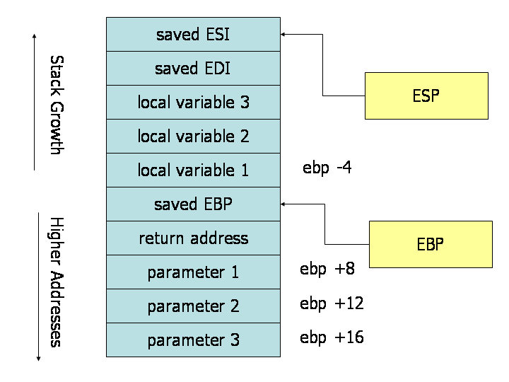
Stack during Subroutine Call
[Thanks to James Peterson for finding and fixing the bug in the original version of this figure!]
A good way to visualize the operation of the calling convention is to draw the contents of the nearby region of the stack during subroutine execution. The image above depicts the contents of the stack during the execution of a subroutine with three parameters and three local variables. The cells depicted in the stack are 32-bit wide memory locations, thus the memory addresses of the cells are 4 bytes apart. The first parameter resides at an offset of 8 bytes from the base pointer. Above the parameters on the stack (and below the base pointer), the call instruction placed the return address, thus leading to an extra 4 bytes of offset from the base pointer to the first parameter. When the ret instruction is used to return from the subroutine, it will jump to the return address stored on the stack.
Caller Rules
To make a subrouting call, the caller should:- Before calling a subroutine, the caller should save the contents of certain registers that are designated caller-saved. The caller-saved registers are EAX, ECX, EDX. Since the called subroutine is allowed to modify these registers, if the caller relies on their values after the subroutine returns, the caller must push the values in these registers onto the stack (so they can be restore after the subroutine returns.
- To pass parameters to the subroutine, push them onto the stack before the call. The parameters should be pushed in inverted order (i.e. last parameter first). Since the stack grows down, the first parameter will be stored at the lowest address (this inversion of parameters was historically used to allow functions to be passed a variable number of parameters).
- To call the subroutine, use the call instruction. This instruction places the return address on top of the parameters on the stack, and branches to the subroutine code. This invokes the subroutine, which should follow the callee rules below.
- Remove the parameters from stack. This restores the stack to its state before the call was performed.
- Restore the contents of caller-saved registers (EAX, ECX, EDX) by popping them off of the stack. The caller can assume that no other registers were modified by the subroutine.
The code below shows a function call that follows the caller rules. The caller is calling a function _myFunc that takes three integer parameters. First parameter is in EAX, the second parameter is the constant 216; the third parameter is in memory location var .
Note that after the call returns, the caller cleans up the stack using the add instruction. We have 12 bytes (3 parameters * 4 bytes each) on the stack, and the stack grows down. Thus, to get rid of the parameters, we can simply add 12 to the stack pointer.push [var] ; Push last parameter first push 216 ; Push the second parameter push eax ; Push first parameter last call _myFunc ; Call the function (assume C naming) add esp, 12
The result produced by _myFunc is now available for use in the register EAX. The values of the caller-saved registers (ECX and EDX), may have been changed. If the caller uses them after the call, it would have needed to save them on the stack before the call and restore them after it.
Callee Rules
The definition of the subroutine should adhere to the following rules at the beginning of the subroutine:- Push the value of EBP onto the stack, and then copy the value of ESP into EBP using the following instructions:
    push ebp
    mov  ebp, esp
This initial action maintains the base pointer, EBP. The base pointer is used by convention as a point of reference for finding parameters and local variables on the stack. When a subroutine is executing, the base pointer holds a copy of the stack pointer value from when the subroutine started executing. Parameters and local variables will always be located at known, constant offsets away from the base pointer value. We push the old base pointer value at the beginning of the subroutine so that we can later restore the appropriate base pointer value for the caller when the subroutine returns. Remember, the caller is not expecting the subroutine to change the value of the base pointer. We then move the stack pointer into EBP to obtain our point of reference for accessing parameters and local variables. - Next, allocate local variables by making space on the stack. Recall, the stack grows down, so to make space on the top of the stack, the stack pointer should be decremented. The amount by which the stack pointer is decremented depends on the number and size of local variables needed. For example, if 3 local integers (4 bytes each) were required, the stack pointer would need to be decremented by 12 to make space for these local variables (i.e., sub esp, 12). As with parameters, local variables will be located at known offsets from the base pointer.
- Next, save the values of the callee-saved registers that will be used by the function. To save registers, push them onto the stack. The callee-saved registers are EBX, EDI, and ESI (ESP and EBP will also be preserved by the calling convention, but need not be pushed on the stack during this step).
- Leave the return value in EAX.
- Restore the old values of any callee-saved registers (EDI and ESI) that were modified. The register contents are restored by popping them from the stack. The registers should be popped in the inverse order that they were pushed.
- Deallocate local variables. The obvious way to do this might be to add the appropriate value to the stack pointer (since the space was allocated by subtracting the needed amount from the stack pointer). In practice, a less error-prone way to deallocate the variables is to move the value in the base pointer into the stack pointer: mov esp, ebp. This works because the base pointer always contains the value that the stack pointer contained immediately prior to the allocation of the local variables.
- Immediately before returning, restore the caller's base pointer value by popping EBP off the stack. Recall that the first thing we did on entry to the subroutine was to push the base pointer to save its old value.
- Finally, return to the caller by executing a ret instruction. This instruction will find and remove the appropriate return address from the stack.
Here is an example function definition that follows the callee rules:
.486
.MODEL FLAT
.CODE
PUBLIC _myFunc
_myFunc PROC
  ; Subroutine Prologue
  push ebp     ; Save the old base pointer value.
  mov ebp, esp ; Set the new base pointer value.
  sub esp, 4   ; Make room for one 4-byte local variable.
  push edi     ; Save the values of registers that the function
  push esi     ; will modify. This function uses EDI and ESI.
  ; (no need to save EBX, EBP, or ESP)

  ; Subroutine Body
  mov eax, [ebp+8]   ; Move value of parameter 1 into EAX
  mov esi, [ebp+12]  ; Move value of parameter 2 into ESI
  mov edi, [ebp+16]  ; Move value of parameter 3 into EDI

  mov [ebp-4], edi   ; Move EDI into the local variable
  add [ebp-4], esi   ; Add ESI into the local variable
  add eax, [ebp-4]   ; Add the contents of the local variable
                     ; into EAX (final result)

  ; Subroutine Epilogue
  pop esi      ; Recover register values
  pop  edi
  mov esp, ebp ; Deallocate local variables
  pop ebp ; Restore the caller's base pointer value
  ret
_myFunc ENDP
END
The subroutine prologue performs the standard actions of saving a snapshot of the stack pointer in EBP (the base pointer), allocating local variables by decrementing the stack pointer, and saving register values on the stack.
In the body of the subroutine we can see the use of the base pointer. Both parameters and local variables are located at constant offsets from the base pointer for the duration of the subroutines execution. In particular, we notice that since parameters were placed onto the stack before the subroutine was called, they are always located below the base pointer (i.e. at higher addresses) on the stack. The first parameter to the subroutine can always be found at memory location [EBP+8], the second at [EBP+12], the third at [EBP+16]. Similarly, since local variables are allocated after the base pointer is set, they always reside above the base pointer (i.e. at lower addresses) on the stack. In particular, the first local variable is always located at [EBP-4], the second at [EBP-8], and so on. This conventional use of the base pointer allows us to quickly identify the use of local variables and parameters within a function body.
The function epilogue is basically a mirror image of the function prologue. The caller's register values are recovered from the stack, the local variables are deallocated by resetting the stack pointer, the caller's base pointer value is recovered, and the ret instruction is used to return to the appropriate code location in the caller.and since updated by Alan Batson, Mike Lack, and Anita Jones.
It was revised for 216 Spring 2006 by David Evans.
| CS216: Program and Data Representation University of Virginia | David Evans evans@cs.virginia.edu Using these Materials |


 766
766

 被折叠的 条评论
为什么被折叠?
被折叠的 条评论
为什么被折叠?
 到【灌水乐园】发言


