


(第一次写博客,如有错误,恳请提出批评。如果对自己有用的话希望可以留下言,也可以交流下。。。让我知道没白写。。。)
本文使用STM32L452RE的板子,在STM32CubeMX工具下进行I2C对PCF8523里面时钟寄存器的读写。
硬件平台:STM32L452RE(NUCLEO)开发板
软件平台:STM32CubeMX + keil 5
1.首先进行STM32CubeMX的配置,
(1)打开STM32CubeMX,选中其中的New Project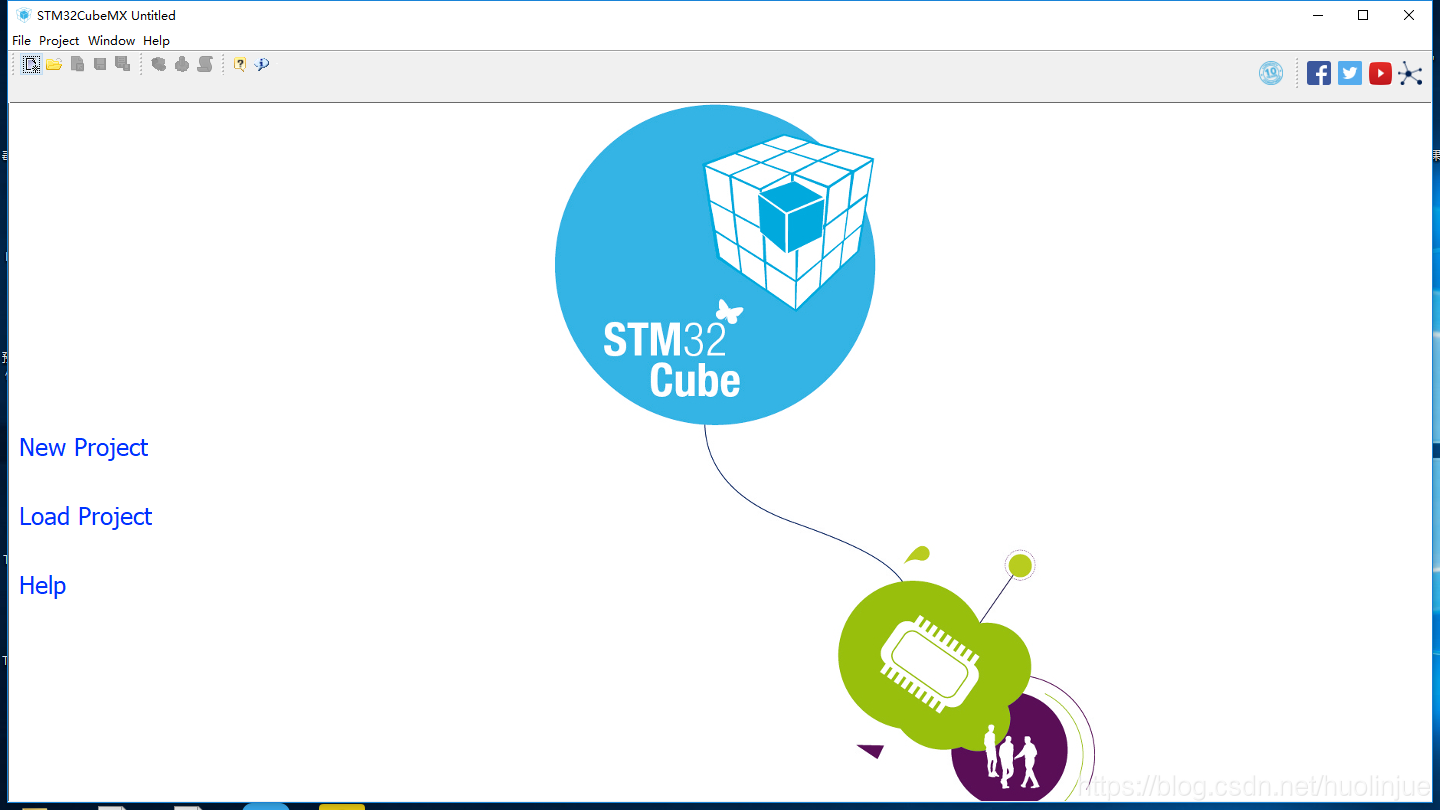
(2)接下来选中我们自己的芯片类型(在此之前你的STM32需要导入芯片的包,这里不具体阐述)左上角可以输入很方便的搜索出来。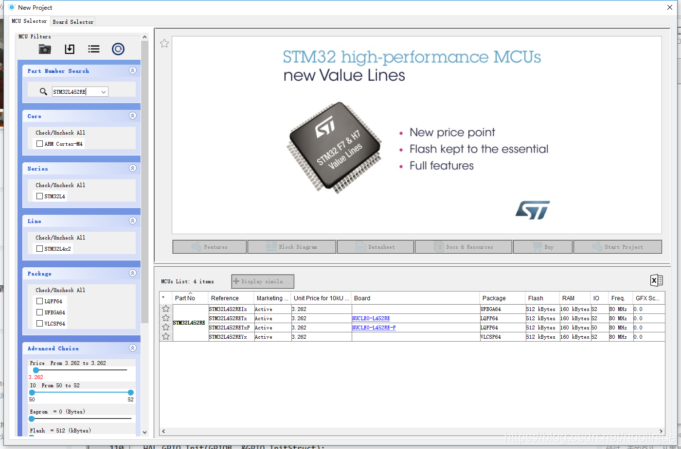
(3)选中其中蓝色的NUCLEO-L452RE为我们这块板子。 点击进入。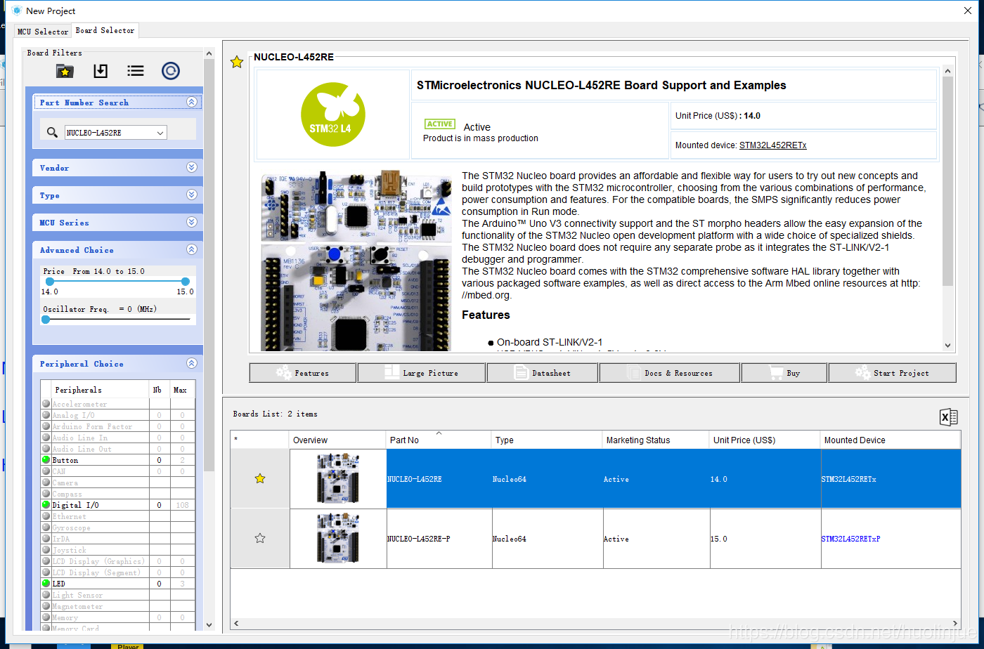
(4)之后进入会让我们选择是否默认配置,我选择了No 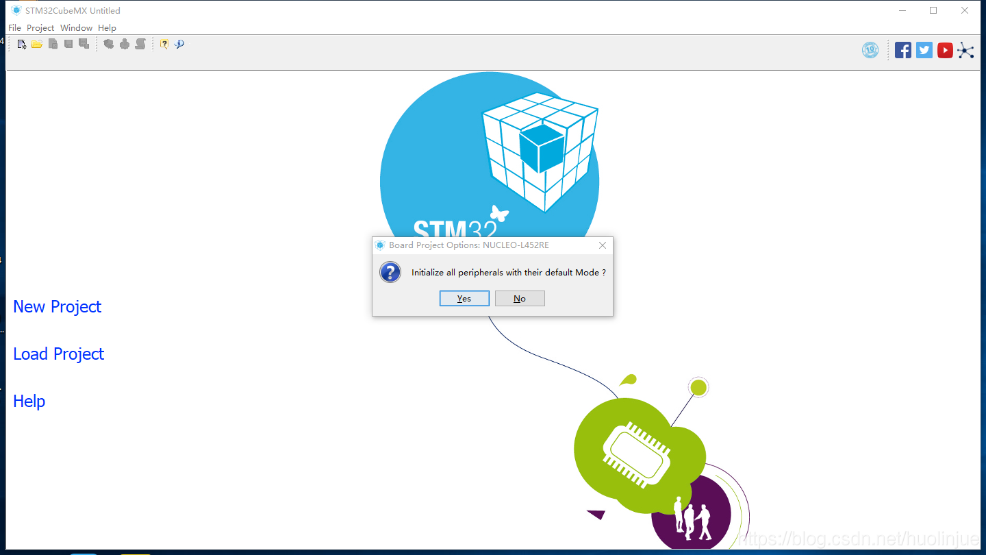
(5)进去后就为这样。。。因为上面我选择的是具体的开发板,所以生成的这些都是该开发板默认的引脚连接。如果我们选择的是单纯芯片,进去进没有这些引脚,只有一些默认电源时钟什么的。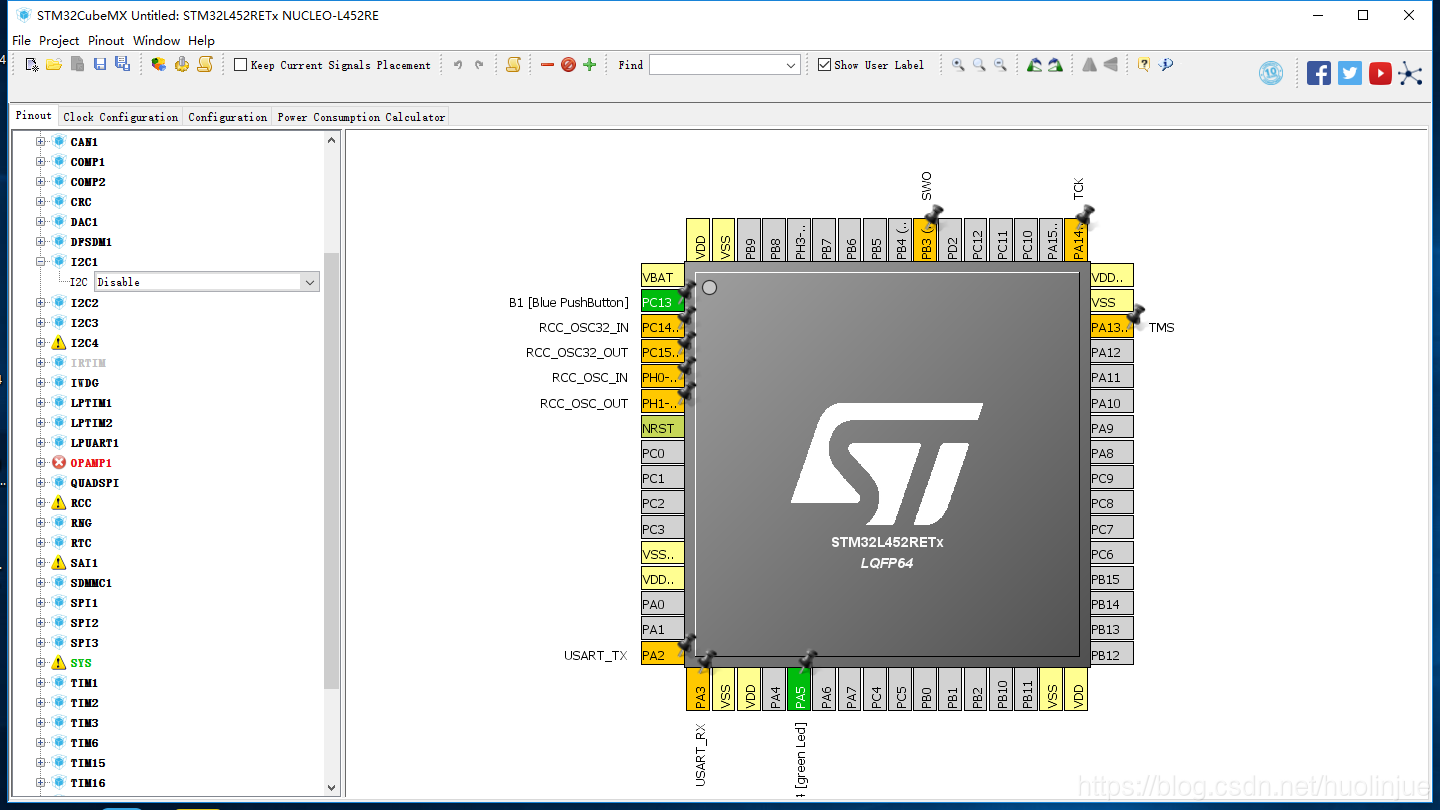
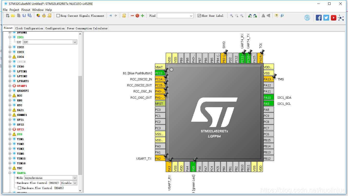
(6)然后配制I2C1使能功能为I2C1,UART4功能为串口,模式为异步,如下:
(7)然后设置时钟,在Clock Configuaration中。我选择了MSI,因为这块板子我之前做串口通信实验时,只有MSI为正确,HSI串口发送过来为乱码。在选择MSI后,有的倍数为红色,修改为正常就行。如下图:
(8)之后基本都采用默认设置,然后选择左上方的Project里面的Settings,自己新建名字,路径都采用默认值(!!!记住一定要全为英文路径,不然会出错,我之前装在了中文路径下面,然后生成的工程里面没有.s文件,很麻烦得自己手动添加,而且还会有其他问题。切记!!!),这里IDE我选择了MDK-ARM V5。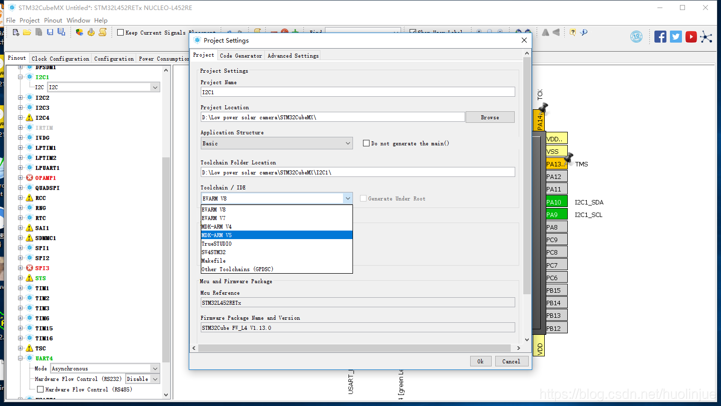
(9)之后再Code Generator中我一般都这样选择,我是看的STM32CubeMX手册中的一个例子这样选,所以我之后的工程一般都这样选择。然后OK

(10)然后点击生成工程。之后Open Project ,因为我电脑有keil5直接就用keil打开了。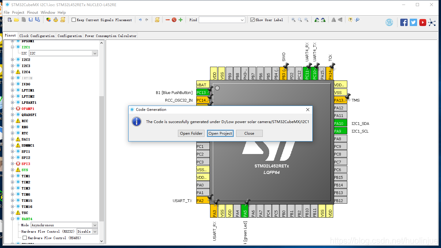
2.关于使用I2C读取PCF的代码
(1)关于PCF8523,我们可以在它的芯片手册中找到I2C控制时它的从地址为0XD0,最后一位为读写为,写为0,读为1。如图: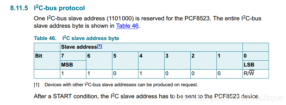
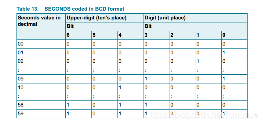
(2)而且我们要读取的为它的秒寄存器,地址为03。如图,而且由于为秒(0-59)因此采用了7位BCD码的形式表示: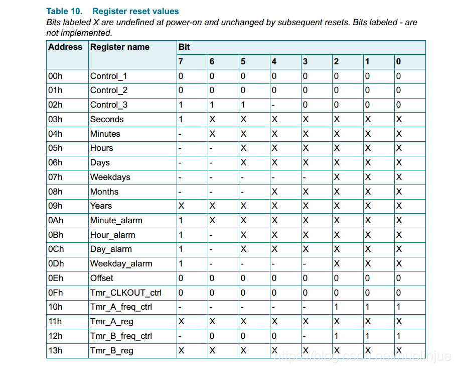
(2)因此我们可以写程序部分,为了串口方便调试,我们采用重写printf输出到串口的方式。而且由于秒最高位为1,因此最后应该减去0x80。程序部分如下:我只改动了main.c。如下,(记得添加的代码最好放在规定的begin 和end区域中间,这样使用STM32CubeMX改动时重新生成代码时你的代码还会在,很方便。)
/**
  ******************************************************************************
  * @file           : main.c
  * @brief          : Main program body
  ******************************************************************************
  ** This notice applies to any and all portions of this file
  * that are not between comment pairs USER CODE BEGIN and
  * USER CODE END. Other portions of this file, whether
  * inserted by the user or by software development tools
  * are owned by their respective copyright owners.
  *
  * COPYRIGHT(c) 2018 STMicroelectronics
  *
  * Redistribution and use in source and binary forms, with or without modification,
  * are permitted provided that the following conditions are met:
  *   1. Redistributions of source code must retain the above copyright notice,
  *      this list of conditions and the following disclaimer.
  *   2. Redistributions in binary form must reproduce the above copyright notice,
  *      this list of conditions and the following disclaimer in the documentation
  *      and/or other materials provided with the distribution.
  *   3. Neither the name of STMicroelectronics nor the names of its contributors
  *      may be used to endorse or promote products derived from this software
  *      without specific prior written permission.
  *
  * THIS SOFTWARE IS PROVIDED BY THE COPYRIGHT HOLDERS AND CONTRIBUTORS "AS IS"
  * AND ANY EXPRESS OR IMPLIED WARRANTIES, INCLUDING, BUT NOT LIMITED TO, THE
  * IMPLIED WARRANTIES OF MERCHANTABILITY AND FITNESS FOR A PARTICULAR PURPOSE ARE
  * DISCLAIMED. IN NO EVENT SHALL THE COPYRIGHT HOLDER OR CONTRIBUTORS BE LIABLE
  * FOR ANY DIRECT, INDIRECT, INCIDENTAL, SPECIAL, EXEMPLARY, OR CONSEQUENTIAL
  * DAMAGES (INCLUDING, BUT NOT LIMITED TO, PROCUREMENT OF SUBSTITUTE GOODS OR
  * SERVICES; LOSS OF USE, DATA, OR PROFITS; OR BUSINESS INTERRUPTION) HOWEVER
  * CAUSED AND ON ANY THEORY OF LIABILITY, WHETHER IN CONTRACT, STRICT LIABILITY,
  * OR TORT (INCLUDING NEGLIGENCE OR OTHERWISE) ARISING IN ANY WAY OUT OF THE USE
  * OF THIS SOFTWARE, EVEN IF ADVISED OF THE POSSIBILITY OF SUCH DAMAGE.
  *
  ******************************************************************************
  */
/* Includes ------------------------------------------------------------------*/
#include "main.h"
#include "stm32l4xx_hal.h"

/* USER CODE BEGIN Includes */
#include <stdio.h>
#include <string.h>
/* USER CODE END Includes */

/* Private variables ---------------------------------------------------------*/
I2C_HandleTypeDef hi2c1;

UART_HandleTypeDef huart4;

/* USER CODE BEGIN PV */
/* Private variables ---------------------------------------------------------*/
#define PCF8523_Write 0xD0
#define PCF8523_Read 0XD1
#define SEC 0x03
#define BufferSize 0x100
uint8_t ReadBuffer[BufferSize];
uint16_t i;
/* USER CODE END PV */

/* Private function prototypes -----------------------------------------------*/
void SystemClock_Config(void);
static void MX_GPIO_Init(void);
static void MX_I2C1_Init(void);
static void MX_UART4_Init(void);

/* USER CODE BEGIN PFP */
/* Private function prototypes -----------------------------------------------*/

/* USER CODE END PFP */

/* USER CODE BEGIN 0 */
#ifdef __GNUC__

/* With GCC, small printf (option LD Linker->Libraries->Small printf

   set to 'Yes') calls __io_putchar() */

#define PUTCHAR_PROTOTYPE int __io_putchar(int ch)

#else

#define PUTCHAR_PROTOTYPE int fputc(int ch, FILE *f)

#endif /* __GNUC__ */

PUTCHAR_PROTOTYPE

{

    HAL_UART_Transmit(&huart4 , (uint8_t *)&ch, 1, 0xFFFF);

    return ch;

}
/* USER CODE END 0 */

/**
  * @brief  The application entry point.
  *
  * @retval None
  */
int main(void)
{
  /* USER CODE BEGIN 1 */

  /* USER CODE END 1 */

  /* MCU Configuration----------------------------------------------------------*/

  /* Reset of all peripherals, Initializes the Flash interface and the Systick. */
  HAL_Init();

  /* USER CODE BEGIN Init */

  /* USER CODE END Init */

  /* Configure the system clock */
  SystemClock_Config();

  /* USER CODE BEGIN SysInit */

  /* USER CODE END SysInit */

  /* Initialize all configured peripherals */
  MX_GPIO_Init();
  MX_I2C1_Init();
  MX_UART4_Init();
  /* USER CODE BEGIN 2 */

  /* USER CODE END 2 */

  /* Infinite loop */
  /* USER CODE BEGIN WHILE */
  while (1)
  {

  /* USER CODE END WHILE */

  /* USER CODE BEGIN 3 */
	  MX_I2C1_Init();

		HAL_I2C_Mem_Read(&hi2c1, PCF8523_Read, 0, I2C_MEMADD_SIZE_8BIT,ReadBuffer,BufferSize, 0x10);
		printf("Time:%02X\n",ReadBuffer[3]-0x80);
		HAL_Delay(1000);
  }
  /* USER CODE END 3 */

}

/**
  * @brief System Clock Configuration
  * @retval None
  */
void SystemClock_Config(void)
{

  RCC_OscInitTypeDef RCC_OscInitStruct;
  RCC_ClkInitTypeDef RCC_ClkInitStruct;
  RCC_PeriphCLKInitTypeDef PeriphClkInit;

    /**Initializes the CPU, AHB and APB busses clocks
    */
  RCC_OscInitStruct.OscillatorType = RCC_OSCILLATORTYPE_MSI;
  RCC_OscInitStruct.MSIState = RCC_MSI_ON;
  RCC_OscInitStruct.MSICalibrationValue = 0;
  RCC_OscInitStruct.MSIClockRange = RCC_MSIRANGE_6;
  RCC_OscInitStruct.PLL.PLLState = RCC_PLL_ON;
  RCC_OscInitStruct.PLL.PLLSource = RCC_PLLSOURCE_MSI;
  RCC_OscInitStruct.PLL.PLLM = 1;
  RCC_OscInitStruct.PLL.PLLN = 20;
  RCC_OscInitStruct.PLL.PLLP = RCC_PLLP_DIV7;
  RCC_OscInitStruct.PLL.PLLQ = RCC_PLLQ_DIV2;
  RCC_OscInitStruct.PLL.PLLR = RCC_PLLR_DIV2;
  if (HAL_RCC_OscConfig(&RCC_OscInitStruct) != HAL_OK)
  {
    _Error_Handler(__FILE__, __LINE__);
  }

    /**Initializes the CPU, AHB and APB busses clocks
    */
  RCC_ClkInitStruct.ClockType = RCC_CLOCKTYPE_HCLK|RCC_CLOCKTYPE_SYSCLK
                              |RCC_CLOCKTYPE_PCLK1|RCC_CLOCKTYPE_PCLK2;
  RCC_ClkInitStruct.SYSCLKSource = RCC_SYSCLKSOURCE_PLLCLK;
  RCC_ClkInitStruct.AHBCLKDivider = RCC_SYSCLK_DIV1;
  RCC_ClkInitStruct.APB1CLKDivider = RCC_HCLK_DIV1;
  RCC_ClkInitStruct.APB2CLKDivider = RCC_HCLK_DIV1;

  if (HAL_RCC_ClockConfig(&RCC_ClkInitStruct, FLASH_LATENCY_2) != HAL_OK)
  {
    _Error_Handler(__FILE__, __LINE__);
  }

  PeriphClkInit.PeriphClockSelection = RCC_PERIPHCLK_UART4|RCC_PERIPHCLK_I2C1;
  PeriphClkInit.Uart4ClockSelection = RCC_UART4CLKSOURCE_PCLK1;
  PeriphClkInit.I2c1ClockSelection = RCC_I2C1CLKSOURCE_PCLK1;
  if (HAL_RCCEx_PeriphCLKConfig(&PeriphClkInit) != HAL_OK)
  {
    _Error_Handler(__FILE__, __LINE__);
  }

    /**Configure the main internal regulator output voltage
    */
  if (HAL_PWREx_ControlVoltageScaling(PWR_REGULATOR_VOLTAGE_SCALE1) != HAL_OK)
  {
    _Error_Handler(__FILE__, __LINE__);
  }

    /**Configure the Systick interrupt time
    */
  HAL_SYSTICK_Config(HAL_RCC_GetHCLKFreq()/1000);

    /**Configure the Systick
    */
  HAL_SYSTICK_CLKSourceConfig(SYSTICK_CLKSOURCE_HCLK);

  /* SysTick_IRQn interrupt configuration */
  HAL_NVIC_SetPriority(SysTick_IRQn, 0, 0);
}

/* I2C1 init function */
static void MX_I2C1_Init(void)
{

  hi2c1.Instance = I2C1;
  hi2c1.Init.Timing = 0x00909BEB;
  hi2c1.Init.OwnAddress1 = 0;
  hi2c1.Init.AddressingMode = I2C_ADDRESSINGMODE_7BIT;
  hi2c1.Init.DualAddressMode = I2C_DUALADDRESS_DISABLE;
  hi2c1.Init.OwnAddress2 = 0;
  hi2c1.Init.OwnAddress2Masks = I2C_OA2_NOMASK;
  hi2c1.Init.GeneralCallMode = I2C_GENERALCALL_DISABLE;
  hi2c1.Init.NoStretchMode = I2C_NOSTRETCH_DISABLE;
  if (HAL_I2C_Init(&hi2c1) != HAL_OK)
  {
    _Error_Handler(__FILE__, __LINE__);
  }

    /**Configure Analogue filter
    */
  if (HAL_I2CEx_ConfigAnalogFilter(&hi2c1, I2C_ANALOGFILTER_ENABLE) != HAL_OK)
  {
    _Error_Handler(__FILE__, __LINE__);
  }

    /**Configure Digital filter
    */
  if (HAL_I2CEx_ConfigDigitalFilter(&hi2c1, 0) != HAL_OK)
  {
    _Error_Handler(__FILE__, __LINE__);
  }

}

/* UART4 init function */
static void MX_UART4_Init(void)
{

  huart4.Instance = UART4;
  huart4.Init.BaudRate = 115200;
  huart4.Init.WordLength = UART_WORDLENGTH_8B;
  huart4.Init.StopBits = UART_STOPBITS_1;
  huart4.Init.Parity = UART_PARITY_NONE;
  huart4.Init.Mode = UART_MODE_TX_RX;
  huart4.Init.HwFlowCtl = UART_HWCONTROL_NONE;
  huart4.Init.OverSampling = UART_OVERSAMPLING_16;
  huart4.Init.OneBitSampling = UART_ONE_BIT_SAMPLE_DISABLE;
  huart4.AdvancedInit.AdvFeatureInit = UART_ADVFEATURE_NO_INIT;
  if (HAL_UART_Init(&huart4) != HAL_OK)
  {
    _Error_Handler(__FILE__, __LINE__);
  }

}

/** Configure pins as
        * Analog
        * Input
        * Output
        * EVENT_OUT
        * EXTI
        * Free pins are configured automatically as Analog (this feature is enabled through
        * the Code Generation settings)
     PA2   ------> USART2_TX
     PA3   ------> USART2_RX
*/
static void MX_GPIO_Init(void)
{

  GPIO_InitTypeDef GPIO_InitStruct;

  /* GPIO Ports Clock Enable */
  __HAL_RCC_GPIOC_CLK_ENABLE();
  __HAL_RCC_GPIOH_CLK_ENABLE();
  __HAL_RCC_GPIOA_CLK_ENABLE();
  __HAL_RCC_GPIOB_CLK_ENABLE();
  __HAL_RCC_GPIOD_CLK_ENABLE();

  /*Configure GPIO pin Output Level */
  HAL_GPIO_WritePin(LD4_GPIO_Port, LD4_Pin, GPIO_PIN_RESET);

  /*Configure GPIO pin : B1_Pin */
  GPIO_InitStruct.Pin = B1_Pin;
  GPIO_InitStruct.Mode = GPIO_MODE_IT_FALLING;
  GPIO_InitStruct.Pull = GPIO_NOPULL;
  HAL_GPIO_Init(B1_GPIO_Port, &GPIO_InitStruct);

  /*Configure GPIO pins : PC0 PC1 PC2 PC3
                           PC4 PC5 PC6 PC7
                           PC8 PC9 PC12 */
  GPIO_InitStruct.Pin = GPIO_PIN_0|GPIO_PIN_1|GPIO_PIN_2|GPIO_PIN_3
                          |GPIO_PIN_4|GPIO_PIN_5|GPIO_PIN_6|GPIO_PIN_7
                          |GPIO_PIN_8|GPIO_PIN_9|GPIO_PIN_12;
  GPIO_InitStruct.Mode = GPIO_MODE_ANALOG;
  GPIO_InitStruct.Pull = GPIO_NOPULL;
  HAL_GPIO_Init(GPIOC, &GPIO_InitStruct);

  /*Configure GPIO pins : PA0 PA1 PA4 PA6
                           PA7 PA8 PA11 PA12
                           PA15 */
  GPIO_InitStruct.Pin = GPIO_PIN_0|GPIO_PIN_1|GPIO_PIN_4|GPIO_PIN_6
                          |GPIO_PIN_7|GPIO_PIN_8|GPIO_PIN_11|GPIO_PIN_12
                          |GPIO_PIN_15;
  GPIO_InitStruct.Mode = GPIO_MODE_ANALOG;
  GPIO_InitStruct.Pull = GPIO_NOPULL;
  HAL_GPIO_Init(GPIOA, &GPIO_InitStruct);

  /*Configure GPIO pins : USART_TX_Pin USART_RX_Pin */
  GPIO_InitStruct.Pin = USART_TX_Pin|USART_RX_Pin;
  GPIO_InitStruct.Mode = GPIO_MODE_AF_PP;
  GPIO_InitStruct.Pull = GPIO_NOPULL;
  GPIO_InitStruct.Speed = GPIO_SPEED_FREQ_VERY_HIGH;
  GPIO_InitStruct.Alternate = GPIO_AF7_USART2;
  HAL_GPIO_Init(GPIOA, &GPIO_InitStruct);

  /*Configure GPIO pin : LD4_Pin */
  GPIO_InitStruct.Pin = LD4_Pin;
  GPIO_InitStruct.Mode = GPIO_MODE_OUTPUT_PP;
  GPIO_InitStruct.Pull = GPIO_NOPULL;
  GPIO_InitStruct.Speed = GPIO_SPEED_FREQ_LOW;
  HAL_GPIO_Init(LD4_GPIO_Port, &GPIO_InitStruct);

  /*Configure GPIO pins : PB0 PB1 PB2 PB10
                           PB11 PB12 PB13 PB14
                           PB15 PB4 PB5 PB6
                           PB7 PB8 PB9 */
  GPIO_InitStruct.Pin = GPIO_PIN_0|GPIO_PIN_1|GPIO_PIN_2|GPIO_PIN_10
                          |GPIO_PIN_11|GPIO_PIN_12|GPIO_PIN_13|GPIO_PIN_14
                          |GPIO_PIN_15|GPIO_PIN_4|GPIO_PIN_5|GPIO_PIN_6
                          |GPIO_PIN_7|GPIO_PIN_8|GPIO_PIN_9;
  GPIO_InitStruct.Mode = GPIO_MODE_ANALOG;
  GPIO_InitStruct.Pull = GPIO_NOPULL;
  HAL_GPIO_Init(GPIOB, &GPIO_InitStruct);

  /*Configure GPIO pin : PD2 */
  GPIO_InitStruct.Pin = GPIO_PIN_2;
  GPIO_InitStruct.Mode = GPIO_MODE_ANALOG;
  GPIO_InitStruct.Pull = GPIO_NOPULL;
  HAL_GPIO_Init(GPIOD, &GPIO_InitStruct);

  /*Configure GPIO pin : PH3 */
  GPIO_InitStruct.Pin = GPIO_PIN_3;
  GPIO_InitStruct.Mode = GPIO_MODE_ANALOG;
  GPIO_InitStruct.Pull = GPIO_NOPULL;
  HAL_GPIO_Init(GPIOH, &GPIO_InitStruct);

}

/* USER CODE BEGIN 4 */

/* USER CODE END 4 */

/**
  * @brief  This function is executed in case of error occurrence.
  * @param  file: The file name as string.
  * @param  line: The line in file as a number.
  * @retval None
  */
void _Error_Handler(char *file, int line)
{
  /* USER CODE BEGIN Error_Handler_Debug */
  /* User can add his own implementation to report the HAL error return state */
  while(1)
  {
  }
  /* USER CODE END Error_Handler_Debug */
}

#ifdef  USE_FULL_ASSERT
/**
  * @brief  Reports the name of the source file and the source line number
  *         where the assert_param error has occurred.
  * @param  file: pointer to the source file name
  * @param  line: assert_param error line source number
  * @retval None
  */
void assert_failed(uint8_t* file, uint32_t line)
{
  /* USER CODE BEGIN 6 */
  /* User can add his own implementation to report the file name and line number,
     tex: printf("Wrong parameters value: file %s on line %d\r\n", file, line) */
  /* USER CODE END 6 */
}
#endif /* USE_FULL_ASSERT */

/**
  * @}
  */

/**
  * @}
  */

/************************ (C) COPYRIGHT STMicroelectronics *****END OF FILE****/
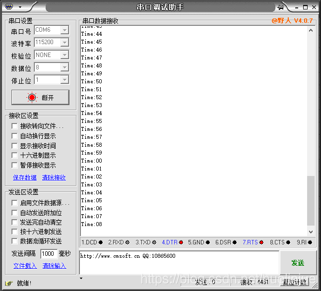
(3)最后通过串口助手查看如下:而且联调时可以用窗口监视器来查看我们ReadBuff[3]中的内容,一直在递加。如下图:
(4)好吧,最后配上一个从其他板子上PCF8523引出来的线以及连接图。。。。(好像是很丑)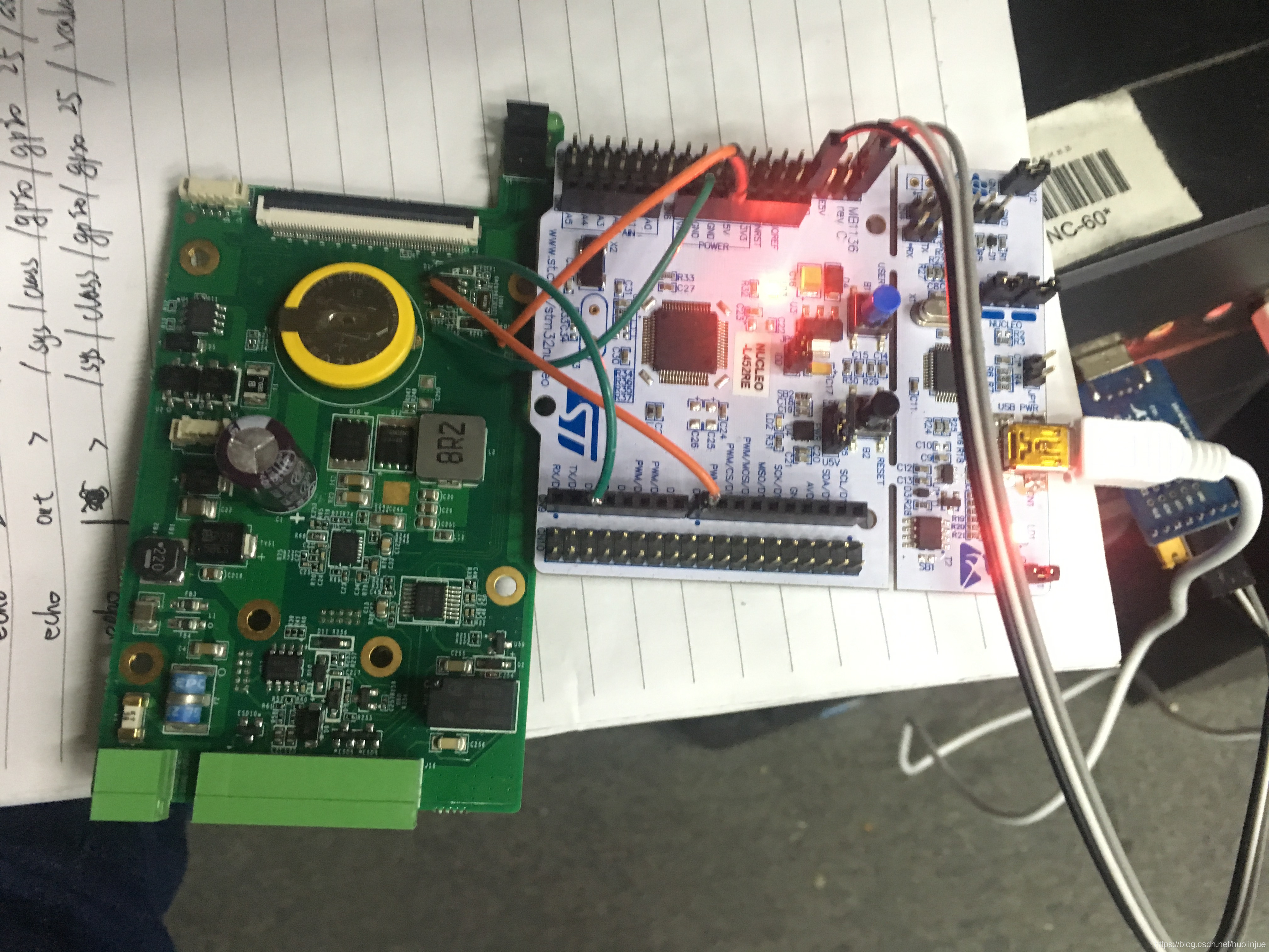
最后,这里借鉴学习了很多其他人的博客。在这里很多就不一一举出来了。。


 2万+
2万+


 被折叠的 条评论
为什么被折叠?
被折叠的 条评论
为什么被折叠?
 到【灌水乐园】发言


