


实验解析
绿色区域就是运营商,黄色区域为公司内部网络,左边蓝色区域为OSPF骨干区域,右边蓝色区域为RIP区域,OSPF区域我们加了两台三层交换机,用到了链路捆绑,还要在与运营商通信的时候转换IP地址,用到了easy IP 技术,RIP中间的路由我们使用了单臂路由的配置
- AR3、AR4、AR5配成RIP
- AR2、AR3、SW1、SW2配成OSPF(骨干区域)
- AR4下方配成单臂路由
- SW1与SW2配E-trunk,分别在SW1、SW2的vlanif逻辑接口上配IP地址
- 各个路由与三层交换机配环回地址
实验目的
在OSPF、RIP协议下实现企业网对运营商的单方向通信,以及实现单方向的映射服务
实验环境
ensp中五台路由,二台三层交换机,五台二层交换机,七台pc,一个服务,wireshark抓包软件
实验过程
首先在华为模拟器ensp中建立拓扑图,按照以下参数为各个路由和交换机配参数
R1:
sys
sysname R1
interface GigabitEthernet0/0/0
 ip address 202.2.2.1 255.255.255.0
interface GigabitEthernet0/0/1
 ip address 202.2.12.1 255.255.255.0
R2:
sys
sysname R2
interface GigabitEthernet0/0/0
 ip address 10.1.113.1 255.255.255.0
interface GigabitEthernet0/0/1
 ip address 10.1.111.1 255.255.255.0
interface GigabitEthernet0/0/2
 ip address 10.1.112.1 255.255.255.0
interface GigabitEthernet6/0/0
 ip address 202.2.12.2 255.255.255.0
 #
 acl number 2000
 rule 5 permit source 10.1.0.0 0.0.255.255
 nat server protocol tcp global 202.2.12.3 www inside 10.1.100.100 www
 nat outbound 2000
 interface LoopBack0
 ip address 2.2.2.2 255.255.255.255
#
ospf 1 router-id 2.2.2.2
 default-route-advertise
 area 0.0.0.0
  network 2.2.2.2 0.0.0.0
  network 10.1.111.0 0.0.0.255
  network 10.1.112.0 0.0.0.255
  network 10.1.113.0 0.0.0.255
#
ip route-static 0.0.0.0 0.0.0.0 202.2.12.1
R3:
sys
sysname R3
interface GigabitEthernet0/0/0
 ip address 10.1.113.2 255.255.255.0
#
interface GigabitEthernet0/0/1
 ip address 10.1.134.1 255.255.255.0
interface LoopBack0
 ip address 3.3.3.3 255.255.255.255
#
ospf 1 router-id 3.3.3.3
 import-route rip 1 cost 5 type 2
 area 0.0.0.0
  network 3.3.3.3 0.0.0.0
  network 10.1.113.0 0.0.0.255
#
rip 1
 default-route originate
 version 2
 network 10.0.0.0
 import-route ospf 1
R4:
sys
sysname R4
interface GigabitEthernet0/0/0.21
 dot1q termination vid 21
 ip address 10.1.21.1 255.255.255.0
 arp broadcast enable
#
interface GigabitEthernet0/0/0.22
 dot1q termination vid 22
 ip address 10.1.22.1 255.255.255.0
 arp broadcast enable
#
interface GigabitEthernet0/0/1
 ip address 10.1.134.2 255.255.255.0
#
interface GigabitEthernet0/0/2
 ip address 10.1.135.1 255.255.255.0
interface LoopBack0
 ip address 4.4.4.4 255.255.255.255
#
rip 1
 version 2
 network 4.0.0.0
 network 10.0.0.0
R5:
sys
sysname R5
interface GigabitEthernet0/0/0
 ip address 10.1.100.1 255.255.255.0
#
interface GigabitEthernet0/0/1
#
interface GigabitEthernet0/0/2
 ip address 10.1.135.2 255.255.255.0
interface LoopBack0
 ip address 5.5.5.5 255.255.255.255
#
rip 1
 version 2
 network 5.0.0.0
 network 10.0.0.0
三层交换机SW1:
sys
sysname SW1
vlan batch 11 12 1000 1001
interface Vlanif11
 ip address 10.1.11.1 255.255.255.0
#
interface Vlanif12
 ip address 10.1.12.1 255.255.255.0
#
interface Vlanif1000
 ip address 10.1.122.11 255.255.255.0
#
interface Vlanif1001
 ip address 10.1.111.12 255.255.255.0
#
interface Eth-Trunk1
 port link-type access
 port default vlan 1000
#
interface GigabitEthernet0/0/1
 port link-type access
 port default vlan 1001
interface GigabitEthernet0/0/11
 eth-trunk 1
interface GigabitEthernet0/0/12
 eth-trunk 1
 interface GigabitEthernet0/0/21
 port link-type access
 port default vlan 11
interface GigabitEthernet0/0/22
 port link-type access
 port default vlan 12
interface LoopBack0
 ip address 11.11.11.11 255.255.255.255
#
ospf 1 router-id 11.11.11.11
 area 0.0.0.0
  network 11.11.11.11 0.0.0.0
  network 10.1.11.0 0.0.0.255
  network 10.1.12.0 0.0.0.255
  network 10.1.122.0 0.0.0.255
  network 10.1.111.0 0.0.0.255
三层交换机SW2:
sys
sysname SW2
vlan batch 13 14 1000 1002
interface Vlanif13
 ip address 10.1.13.1 255.255.255.0
#
interface Vlanif14
 ip address 10.1.14.1 255.255.255.0
#
interface Vlanif1000
 ip address 10.1.122.12 255.255.255.0
#
interface Vlanif1002
 ip address 10.1.112.12 255.255.255.0
#
interface Eth-Trunk1
 port link-type access
 port default vlan 1000
#
interface GigabitEthernet0/0/2
 port link-type access
 port default vlan 1002
interface GigabitEthernet0/0/11
 eth-trunk 1
interface GigabitEthernet0/0/12
 eth-trunk 1
interface GigabitEthernet0/0/23
 port link-type access
 port default vlan 13
#
interface GigabitEthernet0/0/24
 port link-type access
 port default vlan 14
#
ospf 1 router-id 22.22.22.22
 area 0.0.0.0
  network 22.22.22.22 0.0.0.0
  network 10.1.13.0 0.0.0.255
  network 10.1.14.0 0.0.0.255
  network 10.1.122.0 0.0.0.255
  network 10.1.112.0 0.0.0.255
交换机SW3:
sys
sysname SW3
vlan batch 11
#
interface Ethernet0/0/1
 port link-type access
 port default vlan 11
interface GigabitEthernet0/0/1
 port link-type access
 port default vlan 11
交换机SW4:
sys
sysname SW4
vlan batch 12
#
interface Ethernet0/0/1
 port link-type access
 port default vlan 12
 interface GigabitEthernet0/0/1
 port link-type access
 port default vlan 12
交换机SW5:
sys
sysname SW5
vlan batch 13
#
interface Ethernet0/0/1
 port link-type access
 port default vlan 13
 interface GigabitEthernet0/0/1
 port link-type access
 port default vlan 13
交换机SW6:
sys
sysname SW6
vlan batch 14
#
interface Ethernet0/0/1
 port link-type access
 port default vlan 14
 interface GigabitEthernet0/0/1
 port link-type access
 port default vlan 14
交换机SW7:
sys
sysname SW7
vlan batch 21 22
#
interface Ethernet0/0/1
 port link-type access
 port default vlan 21
interface Ethernet0/0/2
 port link-type access
 port default vlan 22
 interface Ethernet0/0/10
 port link-type trunk
 port trunk allow-pass vlan 21 to 22
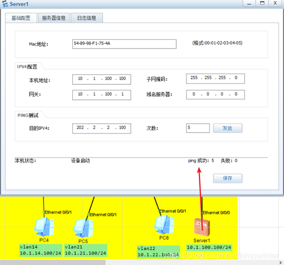
最后我们为七台主机和服务配上IP地址、子网掩码以及网关,服务的IP地址不会配置参照之前的博客
主机1:10.1.11.100/24
主机2:10.1.12.100/24
主机3:10.1.13.100/24
主机4:10.1.14.100/24
主机5:10.1.21.100/24
主机6:10.1.22.100/24
主机7:202.2.2.100/24
server:10.1.100.100/24
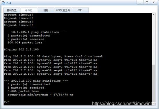
配置完成后我们进入测试阶段
我们抓包查看NAT地址是否转换,转换成功
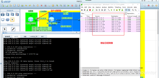
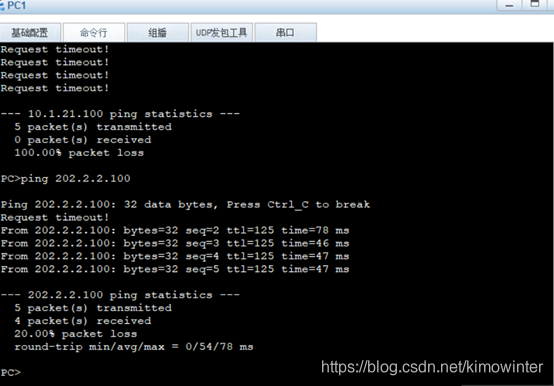
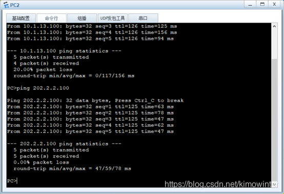
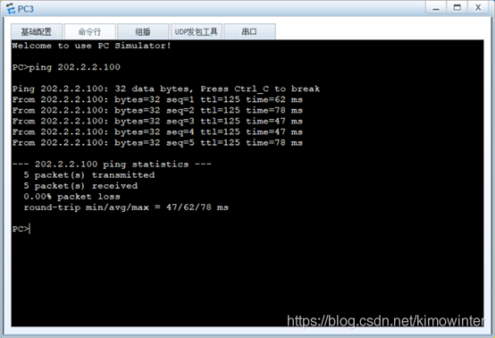
我们再用企业内部的pc和服务分别去ping运营商的pc,全都能ping通,实验成功


 640
640


 被折叠的 条评论
为什么被折叠?
被折叠的 条评论
为什么被折叠?
 到【灌水乐园】发言


