


转载地址:https://blog.csdn.net/cc289123557/article/details/51781771
本文系列文章
建议参考文章Documentation/devicetree/booting-without-of.txt
linux设备树的解释 - 总览
文章从全局介绍了dt使用的整个流程,言简意赅
linux设备树的解释 - DTC编译器
文章介绍了dtc编译器及DT文件组织结构
linux设备树的解释 - DTB文件格式
文章介绍了被编译完成的dtb文件格式,要能够理解内核是怎么把dts转换成device,dtb文件格式是必须了解的
linux设备树的解释 - DT文件数据结构
文章介绍了dts文件里的数据组织结构及各个节点、属性的用途
我们知道linux设备驱动模型是由device-bus-driver组成的,在linux 2.6内核版本上,device是通过arch/arm/mach-some/目录下的board-some-evm.c文件来进行注册的,而到了3.x和4.x版本后,社区引入了设备树(device tree)来代替以前的device注册方法,下面的介绍都是用DT简称来代替设备树
DT使用流程
DT使用流程图,下文详加解释:
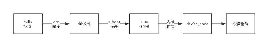
1.DT文件在文件夹/arch/*/boot/dts/目录下,由后缀名为dts和dtsi的文件组成,这些文件里的数据组织结构由其它文章介绍,通过dtc编译器最终把dt文件生成为dtb文件,dtb文件会被烧写在 NAND或者SD或者EMMC存储设备上,然后由u-boot传递给linux内核
2.我们知道uboot是一段引导程序,最终会引导启动linux内核,uboot会传递一些参数给内核,对于arm架构来说,ro/r1/r2寄存器上的参数为:
r0 : 0
r1 : Valid machine type number.
r2 : dtb文件在RAM中的物理地址(以前没有dtb文件时,对应的是TAGlist的物理地址).
3.dtb文件传递给内核后,内核会把dtb文件扩展为device_node结构体链表,最终这些结构体会由设备驱动来使用进行device注册,device_node结构体中一些字段对应的含义如下:
struct device_node {
    const char *name;------------------name属性对应的值
    const char *type;------------------device_type属性对应的值
    phandle phandle;-------------------phandle属性对应的值
    const char *full_name;-------------节点的全名(如:/cpus/cpu0:V1-3;cpu0:V16)

    struct  property *properties;------属性链表
    struct  property *deadprops;-------removed properties
    struct  device_node *parent;-------父节点
    struct  device_node *child;--------子节点
    struct  device_node *sibling;------兄弟节点
    struct  device_node *next;---------同type下一个节点
    struct  device_node *allnext;------所有节点的下一个节点
    struct  kobject kobj;
    unsigned long _flags;
    void    *data;
};dtb转换为device_node是通过函数drivers/of/fdt.c->unflatten_device_tree->unflatten_dt_node完成的;系统初始化时会初始化platform总线上的设备(有simple-bus来决定),具体操作在drivers/of/platform.c->of_platform_populate函数中,函数会把device_nonde转换为platform_device,然后加入到platform_bus的devices链表中
int of_platform_populate(struct device_node *root,
            const struct of_device_id *matches,
            const struct of_dev_auxdata *lookup,
            struct device *parent)
DT文件结构
DT的文件组织结构如图
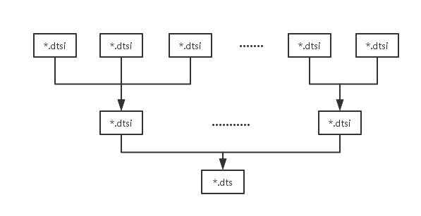
*.dts作为一块板子总的设备组织结构,它会include其他一些有共同特性的文件来,这些文件就是后缀名为*.dtsi的文件
DTC编译
dtc编译器能够把 dts 文件生成为dtb文件,也能把dtb文件生成为dts文件
语法
dtc [-I input-format] [-O output-format] [-o output-filename] [-V output_version] input_filename
参数说明
input-format:
- “dtb”: “blob” format
- “dts”: “source” format.
- “fs” format.
output-format:
- “dtb”: “blob” format
- “dts”: “source” format
- “asm”: assembly language file
output_version:
定义”blob”的版本,在dtb文件的字段中有表示,支持1 2 3和16,默认是3,在16版本上有许多特性改变
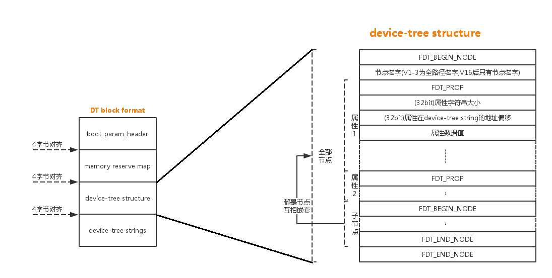
dtb文件格式
dtb文件的格式如下图 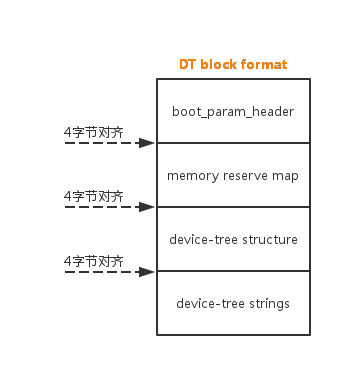
NOTE:不同部分顺序可能不一样
文件头boot_param_header
struct boot_param_header {
        u32     magic;----------------用于标dtb文件头,等于OF_DT_HEADER=“0xd00dfeed”
        u32     totalsize;------------dtb文件大小
        u32     off_dt_struct;--------DT structure偏移
        u32     off_dt_strings;-------DT strings偏移
        u32     off_mem_rsvmap;-------memory reserve map偏移
        u32     version;--------------版本号
        u32     last_comp_version;----兼容最早版本号

        /* version 2 fields below */
        u32     boot_cpuid_phys;------physical CPU id

        /* version 3 fields below */
        u32     size_dt_strings;------size of the strings block

        /* version 17 fields below */
        u32 size_dt_struct;-----------size of the DT structure block
};
保留内存memory reserve map
这段保存的是一个保留内存映射列表,每个表由一对64位的物理地址和大小组成
device-tree structure&strings
由于某些属性(比如compatible)在大多数节点下都会存在,为了减少dtb文件大小,就需要把这些属性字符串只指定一个存储位置即可,这样每个节点的属性只需要按照位置找到属性字符串的位置就可以得到是哪个属性,所以dtb把device-tree strings单独列出来存储,下图是device-tree structure的格式,节点嵌套节点 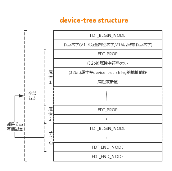
上面的宏定义如下
#define FDT_MAGIC   0xd00dfeed  /* 4: version, 4: total size */
#define FDT_TAGSIZE sizeof(uint32_t)

#define FDT_BEGIN_NODE  0x1     /* Start node: full name */
#define FDT_END_NODE    0x2     /* End node */
#define FDT_PROP    0x3     /* Property: name off, size, content */
#define FDT_NOP     0x4     /* nop */
#define FDT_END     0x9

#define FDT_V1_SIZE (7*sizeof(uint32_t))
#define FDT_V2_SIZE (FDT_V1_SIZE + sizeof(uint32_t))
#define FDT_V3_SIZE (FDT_V2_SIZE + sizeof(uint32_t))
#define FDT_V16_SIZE    FDT_V3_SIZE
#define FDT_V17_SIZE    (FDT_V16_SIZE + sizeof(uint32_t))
总图
DT数据结构总括
一个设备树的总体结构如下
  / o device-tree
      |- name = "device-tree"
      |- model = "MyBoardName"
      |- compatible = "MyBoardFamilyName"
      |- #address-cells = <2>
      |- #size-cells = <2>
      |- linux,phandle = <0>
      |
      o cpus
      | | - name = "cpus"
      | | - linux,phandle = <1>
      | | - #address-cells = <1>
      | | - #size-cells = <0>
      | |
      | o PowerPC,970@0
      |   |- name = "PowerPC,970"
      |   |- device_type = "cpu"
      |   |- reg = <0>
      |   |- clock-frequency = <0x5f5e1000>
      |   |- 64-bit
      |   |- linux,phandle = <2>
      |
      o memory@0
      | |- name = "memory"
      | |- device_type = "memory"
      | |- reg = <0x00000000 0x00000000 0x00000000 0x20000000>
      | |- linux,phandle = <3>
      |
      o chosen
        |- name = "chosen"
        |- bootargs = "root=/dev/sda2"
        |- linux,phandle = <4>
下面是个实际的例子:s3c6410-smdk6410板子的设备树
/ {
    model = "SAMSUNG SMDK6410 board based on S3C6410";
    compatible = "samsung,mini6410", "samsung,s3c6410";

    memory {
        reg = <0x50000000 0x8000000>;
    };

    chosen {
        bootargs = "console=ttySAC0,115200n8 earlyprintk rootwait root=/dev/mmcblk0p1";
    };

    clocks {
        compatible = "simple-bus";
        #address-cells = <1>;
        #size-cells = <0>;

        fin_pll: oscillator@0 {
            compatible = "fixed-clock";
            reg = <0>;
            clock-frequency = <12000000>;
            clock-output-names = "fin_pll";
            #clock-cells = <0>;
        };

        xusbxti: oscillator@1 {
            compatible = "fixed-clock";
            reg = <1>;
            clock-output-names = "xusbxti";
            clock-frequency = <48000000>;
            #clock-cells = <0>;
        };
    };

    srom-cs1@18000000 {
        compatible = "simple-bus";
        #address-cells = <1>;
        #size-cells = <1>;
        reg = <0x18000000 0x8000000>;
        ranges;

        ethernet@18000000 {
            compatible = "smsc,lan9115";
            reg = <0x18000000 0x10000>;
            interrupt-parent = <&gpn>;
            interrupts = <10 IRQ_TYPE_LEVEL_LOW>;
            phy-mode = "mii";
            reg-io-width = <4>;
            smsc,force-internal-phy;
        };
    };
};
从上可以得知设备树是由节点组成的,总体上由一个根节点”/”包含,根节点下包含许多子节点,子节点下又包含子节点,节点中又包含许多属性,下面先介绍单元节点,然后介绍每个属性的含义及表达
单个节点组成
单个节点表示
[label:] node-name[@unit-address] {
   [properties]
   [child nodes]
}
[]表示可选的,一个节点名字组成:
[label:] node-name[@unit-address]
其中node-name是必须有的,@unit-address表示节点所在的地址,label是节点的标签,可以方便其他文件引用此节点,引用的表示为:
&sdhci0 {
    pinctrl-names = "default";
    pinctrl-0 = <&sd0_clk>, <&sd0_cmd>, <&sd0_cd>, <&sd0_bus4>;
    bus-width = <4>;
    status = "okay";
};
sdhci0就是一个label,sdhci0节点在dtsi文件中已经存在了,但是在某一特定板子上要有某些特殊的表示,就可以引用sdhci0节点来定义一些属性
节点下面包含许多属性properties
节点下面包含许多子节点child nodes
属性介绍
cells属性及地址表达
在属性中有一些属性是用来定义子节点的地址规范的,比如属性#address-cells和#size-cells,例如下面的表示:
    #address-cells = <1>;
    #size-cells = <1>;
一个cell可以理解为一小格空间,用<>来表示,里面的数都是32位数据值,和此有关的属性有reg和ranges属性
reg
reg属性的表达为
bus address, size
#address-cells属性定义bus address,#size-cells来定义size,举上面的例子来说:
    srom-cs1@18000000 {
        compatible = "simple-bus";
        #address-cells = <1>;
        #size-cells = <1>;
        reg = <0x18000000 0x8000000>;
        ranges;

        ethernet@18000000 {
            compatible = "smsc,lan9115";
            reg = <0x18000000 0x10000>;
            interrupt-parent = <&gpn>;
            interrupts = <10 IRQ_TYPE_LEVEL_LOW>;
            phy-mode = "mii";
            reg-io-width = <4>;
            smsc,force-internal-phy;
        };
    };
#address-cells = <1>规定了reg = <0x18000000 0x10000>中的0x18000000
#size-cells = <1>规定了reg = <0x18000000 0x10000>中的0x10000
如果#address-cells = <2>,那么reg就应该是像下面这样子的:
reg = < 0x00000000 0x18000000 0x10000>
#address-cells = <2>规定了 0x00000000 0x18000000
还有像这样表达的:
reg = < 0x00000000 0x18000000 0x10000
        0x00000000 0x20000000 0x10000>
这个等同于把两个reg合并到一个reg里面去了,等同于下面的表达
    reg = < 0x00000000 0x18000000 0x10000 >
    reg = < 0x00000000 0x20000000 0x10000 >
用途:reg顾名思义就是代表设备寄存器的地址区间
ranges
ranges的表达为
bus address, parent bus address, size
类似上面reg属性的表达,#address-cells规定了‘bus address, parent bus address‘;#size-cells 规定了‘size‘
用途:ranges属性用于内存的动态映射,在memory节点再详细介绍
“compatible” 属性
compatible属性用于兼容性匹配,在设备驱动中用于和设备驱动来进行匹配,如上面举例:
compatible = "smsc,lan9115";
它会在设备注册中匹配有”smsc,lan9115”标志的驱动,还有一些这样表达:
compatible = "samsung,mini6410", "samsung,s3c6410";
表示会匹配samsung,mini6410和samsung,s3c6410,其实这就是兼容的意思
“name” 属性
name属性现在好多节点都不定义,它类似于device_type属性,在版本16后,如果此属性不存在,那么就会用节点的名字(@前面的名字)来重新定义它
中断属性
interrupts属性和#interrupt-cells属性
#interrupt-cells决定了interrupts有几个值,每个值的定义由中断控制器的具体spec决定
例如:
gic: interrupt-controller@12001000 {
    compatible = "arm,gic-400";
    reg = <0 0x12001000 0 0x1000>,
          <0 0x12002000 0 0x2000>,
          <0 0x12004000 0 0x2000>,
          <0 0x12006000 0 0x2000>;
    #interrupt-cells = <3>;
    interrupt-controller;
    interrupts = <GIC_PPI 9 (GIC_CPU_MASK_SIMPLE(8)
                | IRQ_TYPE_LEVEL_HIGH)>;
};
serial0: serial@1c020000 {
    status = "disabled";
    device_type = "serial";
    compatible = "ns16550a";
    reg = <0 0x1c020000 0x0 0x1000>;
    reg-shift = <2>;
    clock-frequency = <10000000>;
    interrupt-parent = <&gic>;
    interrupts = <0x0 0x4c 0x4>;
};
#interrupt-cells = <3>;决定了interrupts = <0x0 0x4c 0x4>;
OpenPIC的#interrupt-cells = <2>,interrupts的两个值的含义为:中断号和中断触发条件,其中中断触发条件的定义为:
0 = low to high edge sensitive type enabled
1 = active low level sensitive type enabled
2 = active high level sensitive type enabled
3 = high to low edge sensitive type enabled
interrupt-parent属性
此属性决定了节点所依附的中断控制器,如上面的例子中,serial0所依附的中断控制器为gic: interrupt-controller@12001000
属性数据值
某些属性值这么表示:
property = [0x0a 0x0b 0x0c 0x0d 0xde 0xea 0xad 0xbe 0xef];
这是定义属性值为字节数组
property = "a","b","c";
这是定义属性值为字符串数组
还有些属性没值,是空属性
NOTE1:属性就类似于协议的东西,具体驱动中怎么用,可以自己定义
NOTE2:如果你要定义自己的属性,那么最好属性由vendor,string表示
节点介绍
root node
根节点需要有这些属性存在:
- model : this is your board name/model
- #address-cells : address representation for "root" devices
- #size-cells: the size representation for "root" devices
- compatible : the board "family" generally finds its way here,
  for example, if you have 2 board models with a similar layout,
  that typically get driven by the same platform code in the
  kernel, you would specify the exact board model in the
  compatible property followed by an entry that represents the SoC
  model.
/cpus node
节点属性至少有
           #address-cells = <00000001>
           #size-cells    = <00000000>
#address-cells规定了子cpu的地址,见/cpus/* nodes
/cpus/* nodes
节点名字一般这么定义“ < architecture >,< core >”
属性有:
- device_type : has to be "cpu"
- reg : This is the physical CPU number, it's a single 32-bit cell
  and is also used as-is as the unit number for constructing the
  unit name in the full path. For example, with 2 CPUs, you would
  have the full path:
    /cpus/PowerPC,970FX@0
    /cpus/PowerPC,970FX@1
  (unit addresses do not require leading zeroes)
- d-cache-block-size : one cell, L1 data cache block size in bytes (*)
- i-cache-block-size : one cell, L1 instruction cache block size in
  bytes
- d-cache-size : one cell, size of L1 data cache in bytes
- i-cache-size : one cell, size of L1 instruction cache in bytes
其他属性
- timebase-frequency : a cell indicating the frequency of the
  timebase in Hz. This is not directly used by the generic code,
  but you are welcome to copy/paste the pSeries code for setting
  the kernel timebase/decrementer calibration based on this
  value.
- clock-frequency : a cell indicating the CPU core clock frequency
  in Hz. A new property will be defined for 64-bit values, but if
  your frequency is < 4Ghz, one cell is enough. Here as well as
  for the above, the common code doesn't use that property, but
  you are welcome to re-use the pSeries or Maple one. A future
  kernel version might provide a common function for this.
- d-cache-line-size : one cell, L1 data cache line size in bytes
  if different from the block size
- i-cache-line-size : one cell, L1 instruction cache line size in
  bytes if different from the block size
/memory node(s)
定义了板子的物理内存分布
例子:
- device_type : has to be "memory"
- reg : This property contains all the physical memory ranges of
  your board. It's a list of addresses/sizes concatenated
  together, with the number of cells of each defined by the
  #address-cells and #size-cells of the root node. For example,
  with both of these properties being 2 like in the example given
  earlier, a 970 based machine with 6Gb of RAM could typically
  have a "reg" property here that looks like:

  00000000 00000000 00000000 80000000
  00000001 00000000 00000001 00000000

  That is a range starting at 0 of 0x80000000 bytes and a range
  starting at 0x100000000 and of 0x100000000 bytes. You can see
  that there is no memory covering the IO hole between 2Gb and
  4Gb. Some vendors prefer splitting those ranges into smaller
  segments, but the kernel doesn't care.
/chosen node
建议属性
- bootargs : This zero-terminated string is passed as the kernel
  command line
- linux,stdout-path : This is the full path to your standard
  console device if any. Typically, if you have serial devices on
  your board, you may want to put the full path to the one set as
  the default console in the firmware here, for the kernel to pick
  it up as its own default console.
/soc < SOCname> node
此节点适用于SOC(system-on-a-chip),节点名字开始必须是soc(MPC8540->soc8540)
必须的属性
- ranges : Should be defined as specified in 1) to describe the
  translation of SoC addresses for memory mapped SoC registers.
- bus-frequency: Contains the bus frequency for the SoC node.
  Typically, the value of this field is filled in by the boot
  loader.
- compatible : Exact model of the SoC
推荐属性
- reg : This property defines the address and size of the
  memory-mapped registers that are used for the SOC node itself.
  It does not include the child device registers - these will be
  defined inside each child node.  The address specified in the
  "reg" property should match the unit address of the SOC node.
- #address-cells : Address representation for "soc" devices.  The
  format of this field may vary depending on whether or not the
  device registers are memory mapped.  For memory mapped
  registers, this field represents the number of cells needed to
  represent the address of the registers.  For SOCs that do not
  use MMIO, a special address format should be defined that
  contains enough cells to represent the required information.
  See 1) above for more details on defining #address-cells.
- #size-cells : Size representation for "soc" devices
- #interrupt-cells : Defines the width of cells used to represent
   interrupts.  Typically this value is <2>, which includes a
   32-bit number that represents the interrupt number, and a
   32-bit number that represents the interrupt sense and level.
   This field is only needed if the SOC contains an interrupt
   controller.
例子:
soc8540@e0000000 {
    #address-cells = <1>;
    #size-cells = <1>;
    #interrupt-cells = <2>;
    device_type = "soc";
    ranges = <0x00000000 0xe0000000 0x00100000>
    reg = <0xe0000000 0x00003000>;
    bus-frequency = <0>;
}


 3万+
3万+

 被折叠的 条评论
为什么被折叠?
被折叠的 条评论
为什么被折叠?
 到【灌水乐园】发言


