


目录

一、绘制图元
在上一篇博客
中,我们介绍了 图元的类型:三角形、直线和点精灵,现在我们来介绍一下如何绘制图元。
图元是可以用OpenGL ES中的glDrawArrays、glDrawElements、glDrawRangeElements、glDrawArraysInstanced和glDrawElementsInstanced命令绘制的几何形状对象。下面我们来介绍一下这几个API。
1.1 glDrawArrays
1.1.1 glDrawArraysAPI说明
void glDrawArrays (GLenum mode, GLint first, GLsizei count);
参数说明:
-
mode
指定要渲染的图元,有效值为:// 点精灵 GL_POINTS // 直线 GL_LINES GL_LINE_STRIP GL_LINE_LOOP // 三角形 GL_TRIANGLES GL_TRIANGLE_STRIP GL_TRIANGLE_FAN -
first
指定启用的顶点数组中的起始顶点索引 -
count
指定要绘制的顶点数量
1.1.2 glDrawArraysAPI示例
glDrawArrays用元素索引为first到first + count - 1的元素指定的顶点绘制mode指定的图元。
调用
glDrawArrays(GL_TRIANGLES, 0, 6 );
将绘制两个三角形:一个三角形由元素索引(0,1,2)指定,另外一个三角形由元素索引(3,4,5)指定。
类似的,调用
glDrawArrays(GL_TRIANGLE_STRIP, 0, 5 );
将绘制三个三角形:一个三角形由元素索引(0,1,2)指定,第二个三角形由元素索引(2,1,3)指定,最后一个三角形由元素索引(2,3,4)指定
1.2 glDrawElements
1.2.1 glDrawElementsAPI说明
void glDrawElements (GLenum mode, GLsizei count, GLenum type, const void *indices);
参数说明:
-
mode
指定要渲染的图元,有效值为:// 点精灵 GL_POINTS // 直线 GL_LINES GL_LINE_STRIP GL_LINE_LOOP // 三角形 GL_TRIANGLES GL_TRIANGLE_STRIP GL_TRIANGLE_FAN -
count
指定要绘制的索引数量 -
type
指定indices中保存的元素索引类型,有效值为:- GL_UNSIGNED_BYTE
- GL_UNSIGNED_SHORT
- GL_UNSIGNED_INT
-
indices
指向元素索引存储位置的指针
1.3 glDrawRangeElements
1.3.1 glDrawRangeElementsAPI说明
void glDrawRangeElements (GLenum mode, GLuint start, GLuint end, GLsizei count, GLenum type, const void *indices);
参数说明:
-
mode
指定要渲染的图元,有效值为:// 点精灵 GL_POINTS // 直线 GL_LINES GL_LINE_STRIP GL_LINE_LOOP // 三角形 GL_TRIANGLES GL_TRIANGLE_STRIP GL_TRIANGLE_FAN -
start
指定indices中的最小数组索引 -
end
指定indices中的最大数组索引 -
count
指定要绘制的索引数量 -
type
指定indices中保存的元素索引类型,有效值为:- GL_UNSIGNED_BYTE
- GL_UNSIGNED_SHORT
- GL_UNSIGNED_INT
-
indices
指向元素索引存储位置的指针
1.4 如何选择?
如果你又一个由一系列顺序元素索引描述的图元,且几何形状的顶点不共享,则glDrawArrays很好用。但是,游戏或者其他3D应用程序使用的典型对象由多个三角形网格组成,其中的元素索引可能不一定按照顺序,顶点通常在网格的三角形之间共享。
考虑如下图所示的立方体:
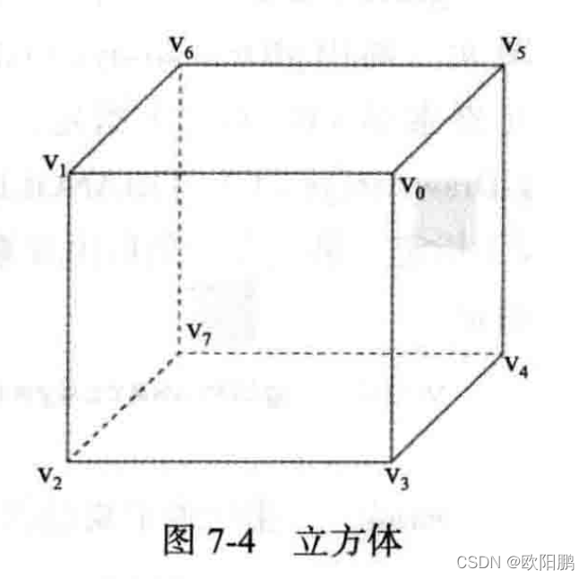
1.4.1 用glDrawArrays绘制
如果我们用glDrawArrays绘制,则代码如下:
#include <GLUtils.h>

#define VERTEX_POS_INDX 0
#define NUM_FACES 6

GLfloat vertivces[] = { ... } ;  // (x,y,z) per vertex

glEnableVertexAttribArray ( VERTEX_POS_INDX );
glVertexAttribPointer( VERTEX_POS_INDX , 3, GL_FLOAT, GL_FALSE, 0 ,vertivces);

for(int i = 0; i< NUM_FACES; i++)
{
	glDrawArrays(GL_TRIANGLE_FAN, i * 4, 4 );
}

// or

glDrawArrays(GL_TRIANGLES , 36 );
为了用glDrawArrays绘制这个立方体,需要为立方体的每一面调用glDrawArrays。
共享的顶点必须重复,这意味着
- 如果将每面当做
GL_TRIANGLE_FAN绘制,则需要分配24个顶点 - 如果将每面当做
GL_TRIANGLES绘制,则需要分配36个顶点
而不是8个顶点,这显然不是一个高效的方法。
1.4.2 用glDrawElements绘制
用glDrawElements绘制同一个立方体的代码如下:
#define VERTEX_POS_INDX 0
GLfloat vertivces[] = {  } ;  // (x,y,z) per vertex
GLubyte indices[36] = {
        0,1,2,  0,2,3,
        0,3,4,  0,4,5,
        0,5,6,  0,6,1,

        7,1,6,  7,2,1,
        7,5,4,  7,6,5,
        7,3,2,  7,4,3
};
glEnableVertexAttribArray ( VERTEX_POS_INDX );
glVertexAttribPointer( VERTEX_POS_INDX , 3, GL_FLOAT, GL_FALSE, 0 ,vertivces);
glDrawElements( GL_TRIANGLES, sizeof(indices) / sizeof( GLubyte),
                GL_UNSIGNED_BYTE , indices);
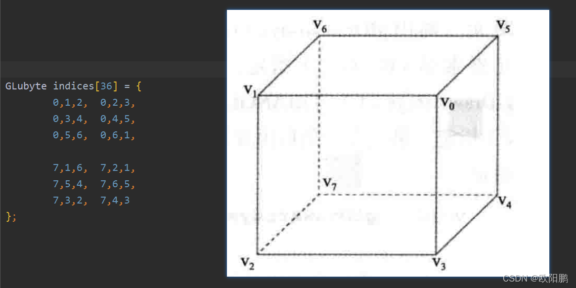
即时我们用glDrawElements绘制三角形,用glDrawArrays和glDrawElements绘制一个三角扇形,我们的应用程序在GPU上运行的也比glDrawArrays更快。
1.5 图元重启
1.5.1 使用图元重启的作用
使用图元重启的作用:
- 可以在一次绘图调用中渲染多个不相连的图元(例如三角扇形或者条带)。这对于降低绘图API调用的开销是有利的。
- 图元重启的另一种方法是生成退化三角形,这种方法较不简洁。
1.5.2 在索引列表中插入一个特殊索引来重启一个用于索引绘图调用
使用图元,可以通过在索引列表中插入一个特殊索引来重启一个用于索引绘图调用(如glDrawElements、glDrawRangeElements、glDrawElementsInstanced)的图元。
这个特殊索引是该索引类型的最大可能索引(例如,索引类型为GL_UNSIGNED_BYTE是为255,索引类型为GL_UNSIGNED_SHORT时为65535)。
例如,假定两个三角形条带分别有元素索引 (0,1,2,3)和 (8,9,10,11)。如果我们想利用图元重启在一次调用glDrawElement***中绘制两个条带,索引类型为GL_UNSIGNED_BYTE,则组合的元素索引列表为(0,1,2,3 ,255, 8,9,10,11)。
1.5.3 启用和禁用图元重启
可以用如下代码启用和禁用图元重启:
// 启用图元重启
glEnable( GL_PRIMITIVE_RESTART_FIXED_INDEX );

// Draw primitives

// 禁用图元重启
glDisable( GL_PRIMITIVE_RESTART_FIXED_INDEX );
1.6 驱动顶点
如果没有限定符,那么顶点着色器的输出值在图元中使用线性插值。
但是,使用平面着色时没有发生插值。因为没有发生插值,所以片段着色器中只有一个顶点值可用。
对于给定的图元实例,这个驱动顶点确定使用顶点着色器的哪一个顶点输出,因为只能使用一个顶点。
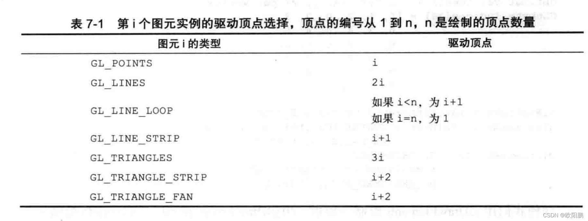
下表展示了驱动顶点选择的规则:
表:第
i个图元实例的驱动顶点选择,顶点的编号从1到n,n是绘制的顶点数量
图元i的类型 | 驱动顶点 |
|---|---|
GL_POINTS | i |
GL_LINES | 2i |
GL_LINE_LOOP | 如果 i < n, 则为 i + 1 |
GL_LINE_STRIP | 如果 i = n, 则为 1 |
GL_TRIANGLES | i + 1 |
GL_TRIANGLE_STRIP | 3i |
GL_TRIANGLE_FAN | i + 2 |
1.7 几何形状实例化
1.7.1 几何形状实例化的作用
- 几何形状实例化很高效,可以用一次API调用多次渲染具有不同属性(例如不同的变换矩阵、颜色或者大小)的一个对象。
这一功能在渲染大量类似对象时很有用,例如对人群的渲染。 - 几何形状实例化降低了向OpenGL ES 引擎发送许多API调用的CPU处理开销。
1.7.2 使用几何形状实例化
要使用几何形状实例化绘图调用渲染,可以使用如下命令:
glDrawArraysInstancedglDrawElementsInstanced
void glDrawArraysInstanced (GLenum mode, GLint first,
                       GLsizei count, GLsizei instancecount);

void glDrawElementsInstanced (GLenum mode, GLsizei count,
						GLenum type, const void *indices,
						GLsizei instancecount);
参数说明:
-
mode
指定要渲染的图元,有效值为:// 点精灵 GL_POINTS // 直线 GL_LINES GL_LINE_STRIP GL_LINE_LOOP // 三角形 GL_TRIANGLES GL_TRIANGLE_STRIP GL_TRIANGLE_FAN -
fisrt
指定启用的顶点数组中的起始顶点索引(仅限glDrawArraysInstanced) -
count
指定要绘制的索引数量 -
type
指定indices中保存的元素索引类型(仅限glDrawElementsInstanced),有效值为:- GL_UNSIGNED_BYTE
- GL_UNSIGNED_SHORT
- GL_UNSIGNED_INT
-
indices
指向元素索引存储位置的指针(仅限glDrawElementsInstanced) -
instancecount
指定绘图的图元实例数量
可以使用两种方法访问每个实例的数据。
1.7.2.1 glDrawArraysInstanced
第一个方法是用如下命令指示OpenGL ES对每个实例读取一次或者多次顶点属性:
void glVertexAttribDivisor (GLuint index, GLuint divisor);
参数说明:
- index
指定通用顶点属性索引 - divisor
指定index位置的通用属性更新之间传递的实例数量
默认情况下,如果没有指定glVertexAttribDivisor 或者顶点属性的divisor等于0,对每个顶点将读取一次顶点属性。如果divisor等于1,对每个图元实例读取一次顶点属性
1.7.2.2 glDrawElementsInstanced
第二个方法是使用内建输入变量 gl_InstanceID 作为顶点着色器中的缓冲区索引,以访问每个实例的数据。使用前面提到的几何形状实例化API调用时,gl_InstanceID将保存当前图元实例的索引。使用非实例化绘图调用时,gl_InstanceID将返回0.
1.7.3 实战一下
下面两个代码片段说明如何用一次实例化绘图调用绘制多个几何形状(例如立方体),其中每个立方体实例的颜色不同。
首先,我们创建一个颜色缓冲区,用于保存以后用于实例化绘图调用的多种颜色数据(每个实例一个颜色)。
// Random color for each instance
   {
      GLubyte colors[NUM_INSTANCES][4];
      int instance;

      srandom ( 0 );

      for ( instance = 0; instance < NUM_INSTANCES; instance++ )
      {
         colors[instance][0] = random() % 255;
         colors[instance][1] = random() % 255;
         colors[instance][2] = random() % 255;
         colors[instance][3] = 0;
      }

      glGenBuffers ( 1, &userData->colorVBO );
      glBindBuffer ( GL_ARRAY_BUFFER, userData->colorVBO );
      glBufferData ( GL_ARRAY_BUFFER, NUM_INSTANCES * 4, colors, GL_STATIC_DRAW );
   }
创建和填充颜色缓冲区之后,我们可以绑定颜色缓冲区,将其作为几何形状的顶点属性之一。然后,指定顶点属性因数1,为每个图元实例读取颜色。最后,用一次实例化绘图调用绘制立方体。
  // Load the instance color buffer
   glBindBuffer ( GL_ARRAY_BUFFER, userData->colorVBO );
   glVertexAttribPointer ( COLOR_LOC, 4, GL_UNSIGNED_BYTE,
                           GL_TRUE, 4 * sizeof ( GLubyte ), ( const void * ) NULL );
   glEnableVertexAttribArray ( COLOR_LOC );

   // Set one color per instance
   glVertexAttribDivisor ( COLOR_LOC, 1 );

   // 省略其他代码

   // Bind the index buffer
   glBindBuffer ( GL_ELEMENT_ARRAY_BUFFER, userData->indicesIBO );

   // Draw the cubes
   glDrawElementsInstanced ( GL_TRIANGLES, userData->numIndices,
   						GL_UNSIGNED_INT, ( const void * ) NULL, NUM_INSTANCES );
完整代码为:
#include <stdlib.h>
#include <math.h>
#include "esUtil.h"

#ifdef _WIN32
#define srandom srand
#define random rand
#endif


#define NUM_INSTANCES   100
#define POSITION_LOC    0
#define COLOR_LOC       1
#define MVP_LOC         2

typedef struct
{
   // Handle to a program object
   GLuint programObject;

   // VBOs
   GLuint positionVBO;
   GLuint colorVBO;
   GLuint mvpVBO;
   GLuint indicesIBO;

   // Number of indices
   int       numIndices;

   // Rotation angle
   GLfloat   angle[NUM_INSTANCES];

} UserData;

///
// Initialize the shader and program object
//
int Init ( ESContext *esContext )
{
   GLfloat *positions;
   GLuint *indices;

   UserData *userData = esContext->userData;
   const char vShaderStr[] =
      "#version 300 es                             \n"
      "layout(location = 0) in vec4 a_position;    \n"
      "layout(location = 1) in vec4 a_color;       \n"
      "layout(location = 2) in mat4 a_mvpMatrix;   \n"
      "out vec4 v_color;                           \n"
      "void main()                                 \n"
      "{                                           \n"
      "   v_color = a_color;                       \n"
      "   gl_Position = a_mvpMatrix * a_position;  \n"
      "}                                           \n";

   const char fShaderStr[] =
      "#version 300 es                                \n"
      "precision mediump float;                       \n"
      "in vec4 v_color;                               \n"
      "layout(location = 0) out vec4 outColor;        \n"
      "void main()                                    \n"
      "{                                              \n"
      "  outColor = v_color;                          \n"
      "}                                              \n";

   // Load the shaders and get a linked program object
   userData->programObject = esLoadProgram ( vShaderStr, fShaderStr );

   // Generate the vertex data
   userData->numIndices = esGenCube ( 0.1f, &positions,
                                      NULL, NULL, &indices );

   // Index buffer object
   glGenBuffers ( 1, &userData->indicesIBO );
   glBindBuffer ( GL_ELEMENT_ARRAY_BUFFER, userData->indicesIBO );
   glBufferData ( GL_ELEMENT_ARRAY_BUFFER, sizeof ( GLuint ) * userData->numIndices, indices, GL_STATIC_DRAW );
   glBindBuffer ( GL_ELEMENT_ARRAY_BUFFER, 0 );
   free ( indices );

   // Position VBO for cube model
   glGenBuffers ( 1, &userData->positionVBO );
   glBindBuffer ( GL_ARRAY_BUFFER, userData->positionVBO );
   glBufferData ( GL_ARRAY_BUFFER, 24 * sizeof ( GLfloat ) * 3, positions, GL_STATIC_DRAW );
   free ( positions );

   // Random color for each instance
   {
      GLubyte colors[NUM_INSTANCES][4];
      int instance;

      srandom ( 0 );

      for ( instance = 0; instance < NUM_INSTANCES; instance++ )
      {
         colors[instance][0] = random() % 255;
         colors[instance][1] = random() % 255;
         colors[instance][2] = random() % 255;
         colors[instance][3] = 0;
      }

      glGenBuffers ( 1, &userData->colorVBO );
      glBindBuffer ( GL_ARRAY_BUFFER, userData->colorVBO );
      glBufferData ( GL_ARRAY_BUFFER, NUM_INSTANCES * 4, colors, GL_STATIC_DRAW );
   }

   // Allocate storage to store MVP per instance
   {
      int instance;

      // Random angle for each instance, compute the MVP later
      for ( instance = 0; instance < NUM_INSTANCES; instance++ )
      {
         userData->angle[instance] = ( float ) ( random() % 32768 ) / 32767.0f * 360.0f;
      }

      glGenBuffers ( 1, &userData->mvpVBO );
      glBindBuffer ( GL_ARRAY_BUFFER, userData->mvpVBO );
      glBufferData ( GL_ARRAY_BUFFER, NUM_INSTANCES * sizeof ( ESMatrix ), NULL, GL_DYNAMIC_DRAW );
   }
   glBindBuffer ( GL_ARRAY_BUFFER, 0 );

   glClearColor ( 1.0f, 1.0f, 1.0f, 0.0f );
   return GL_TRUE;
}


///
// Update MVP matrix based on time
//
void Update ( ESContext *esContext, float deltaTime )
{
   UserData *userData = ( UserData * ) esContext->userData;
   ESMatrix *matrixBuf;
   ESMatrix perspective;
   float    aspect;
   int      instance = 0;
   int      numRows;
   int      numColumns;


   // Compute the window aspect ratio
   aspect = ( GLfloat ) esContext->width / ( GLfloat ) esContext->height;

   // Generate a perspective matrix with a 60 degree FOV
   esMatrixLoadIdentity ( &perspective );
   esPerspective ( &perspective, 60.0f, aspect, 1.0f, 20.0f );

   glBindBuffer ( GL_ARRAY_BUFFER, userData->mvpVBO );
   matrixBuf = ( ESMatrix * ) glMapBufferRange ( GL_ARRAY_BUFFER, 0, sizeof ( ESMatrix ) * NUM_INSTANCES, GL_MAP_WRITE_BIT );

   // Compute a per-instance MVP that translates and rotates each instance differnetly
   numRows = ( int ) sqrtf ( NUM_INSTANCES );
   numColumns = numRows;

   for ( instance = 0; instance < NUM_INSTANCES; instance++ )
   {
      ESMatrix modelview;
      float translateX = ( ( float ) ( instance % numRows ) / ( float ) numRows ) * 2.0f - 1.0f;
      float translateY = ( ( float ) ( instance / numColumns ) / ( float ) numColumns ) * 2.0f - 1.0f;

      // Generate a model view matrix to rotate/translate the cube
      esMatrixLoadIdentity ( &modelview );

      // Per-instance translation
      esTranslate ( &modelview, translateX, translateY, -2.0f );

      // Compute a rotation angle based on time to rotate the cube
      userData->angle[instance] += ( deltaTime * 40.0f );

      if ( userData->angle[instance] >= 360.0f )
      {
         userData->angle[instance] -= 360.0f;
      }

      // Rotate the cube
      esRotate ( &modelview, userData->angle[instance], 1.0, 0.0, 1.0 );

      // Compute the final MVP by multiplying the
      // modevleiw and perspective matrices together
      esMatrixMultiply ( &matrixBuf[instance], &modelview, &perspective );
   }

   glUnmapBuffer ( GL_ARRAY_BUFFER );
}

///
// Draw a triangle using the shader pair created in Init()
//
void Draw ( ESContext *esContext )
{
   UserData *userData = esContext->userData;

   // Set the viewport
   glViewport ( 0, 0, esContext->width, esContext->height );

   // Clear the color buffer
   glClear ( GL_COLOR_BUFFER_BIT | GL_DEPTH_BUFFER_BIT );

   // Use the program object
   glUseProgram ( userData->programObject );

   // Load the vertex position
   glBindBuffer ( GL_ARRAY_BUFFER, userData->positionVBO );
   glVertexAttribPointer ( POSITION_LOC, 3, GL_FLOAT,
                           GL_FALSE, 3 * sizeof ( GLfloat ), ( const void * ) NULL );
   glEnableVertexAttribArray ( POSITION_LOC );

   // Load the instance color buffer
   glBindBuffer ( GL_ARRAY_BUFFER, userData->colorVBO );
   glVertexAttribPointer ( COLOR_LOC, 4, GL_UNSIGNED_BYTE,
                           GL_TRUE, 4 * sizeof ( GLubyte ), ( const void * ) NULL );
   glEnableVertexAttribArray ( COLOR_LOC );

   // Set one color per instance
   glVertexAttribDivisor ( COLOR_LOC, 1 );


   // Load the instance MVP buffer
   glBindBuffer ( GL_ARRAY_BUFFER, userData->mvpVBO );

   // Load each matrix row of the MVP.  Each row gets an increasing attribute location.
   glVertexAttribPointer ( MVP_LOC + 0, 4, GL_FLOAT, GL_FALSE, sizeof ( ESMatrix ), ( const void * ) NULL );
   glVertexAttribPointer ( MVP_LOC + 1, 4, GL_FLOAT, GL_FALSE, sizeof ( ESMatrix ), ( const void * ) ( sizeof ( GLfloat ) * 4 ) );
   glVertexAttribPointer ( MVP_LOC + 2, 4, GL_FLOAT, GL_FALSE, sizeof ( ESMatrix ), ( const void * ) ( sizeof ( GLfloat ) * 8 ) );
   glVertexAttribPointer ( MVP_LOC + 3, 4, GL_FLOAT, GL_FALSE, sizeof ( ESMatrix ), ( const void * ) ( sizeof ( GLfloat ) * 12 ) );
   glEnableVertexAttribArray ( MVP_LOC + 0 );
   glEnableVertexAttribArray ( MVP_LOC + 1 );
   glEnableVertexAttribArray ( MVP_LOC + 2 );
   glEnableVertexAttribArray ( MVP_LOC + 3 );

   // One MVP per instance
   glVertexAttribDivisor ( MVP_LOC + 0, 1 );
   glVertexAttribDivisor ( MVP_LOC + 1, 1 );
   glVertexAttribDivisor ( MVP_LOC + 2, 1 );
   glVertexAttribDivisor ( MVP_LOC + 3, 1 );

   // Bind the index buffer
   glBindBuffer ( GL_ELEMENT_ARRAY_BUFFER, userData->indicesIBO );

   // Draw the cubes
   glDrawElementsInstanced ( GL_TRIANGLES, userData->numIndices, GL_UNSIGNED_INT, ( const void * ) NULL, NUM_INSTANCES );
}

///
// Cleanup
//
void Shutdown ( ESContext *esContext )
{
   UserData *userData = esContext->userData;

   glDeleteBuffers ( 1, &userData->positionVBO );
   glDeleteBuffers ( 1, &userData->colorVBO );
   glDeleteBuffers ( 1, &userData->mvpVBO );
   glDeleteBuffers ( 1, &userData->indicesIBO );

   // Delete program object
   glDeleteProgram ( userData->programObject );
}


int esMain ( ESContext *esContext )
{
   esContext->userData = malloc ( sizeof ( UserData ) );

   esCreateWindow ( esContext, "Instancing", 640, 480, ES_WINDOW_RGB | ES_WINDOW_DEPTH );

   if ( !Init ( esContext ) )
   {
      return GL_FALSE;
   }

   esRegisterShutdownFunc ( esContext, Shutdown );
   esRegisterUpdateFunc ( esContext, Update );
   esRegisterDrawFunc ( esContext, Draw );

   return GL_TRUE;
}
1.8 性能提示
应用程序应该确保用尽可能大的图元尺寸调用glDrawElements和glDrawElementsInstanced。
-
如果我们绘制
GL_TRIANGLES,这很容易做到, -
但是,如果有三角扇形条带或者扇形的网格,可以用图元重启将这些网格连接在一起,而不用对每个三角扇形条带网格单独调用
glDrawElements和glDrawElementsInstanced。 -
如果无法使用图元重启机制将网格连接在一起(为了维护与旧版本的OpenGL ES的兼容性),可以添加造成退化三角形的元素索引,代价是使用更多的索引,并且需要注意这里讨论的一些事项。退化三角形是两个或者更多顶点相同的三角形。GPU可以非常简单地检测和拒绝退化三角形,所以这是很好的性能改进,我们可以将一个很大的图元放入由GPU渲染的队列。
为了连接不同网格而添加的元素索引(或者退化三角形)数量取决于每个网格是三角扇形还是三角形条带以及每个条带中定义的索引数量。三角形条带网格的索引数量很重要,因为我们必须保留从跨越连接起来的不同网格的条带的一个三角形到下一个三角形的弯曲顺序。
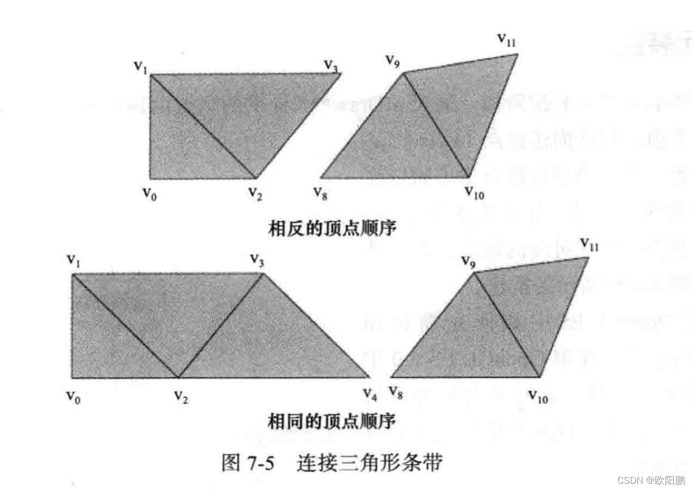
连接不同的三角形条带时,我们需要检查两个相互连接的条带的最后一个三角形和第一个三角形的顺序。
如下图所示,描述三角形条带中偶数编号的三角形的顶点顺序与描述同一个条带中奇数编号的三角形的顶点顺序不同。
有两种情况需要处理:
- 第一个三角形条带的奇数编号的三角形连接到第二个三角形条带的第一个(因而是偶数编号的)三角形
- 第一个三角形条带的偶数编号的三角形连接到第二个三角形条带的第一个(因而是偶数编号的)三角形
下图展示了上述两种情况的不同三角形条带,其中的条带必须连接,使我们用一次
glDrawElements***调用绘制两者。
-
两个相互连接的三角形条带的最后一个三角形和第一个三角形顶点顺序相反的情况
对于上图中两个相互连接的三角形条带的最后一个三角形和第一个三角形顶点顺序相反的情况,每个三角形条带的元素索引分别是(0,1,2,3)和(8,9,10,11)。如果我们用一次glDrawElements***调用绘制两个条带,组合的元素索引列表将为
(0,1,2,3, 3,8, 8,9,10,11)。这个新的元素索引绘制如下三角形:
(0,1,2)、(2,1,3)、(2,3,3)、(3,3,8)、(3,8,8)、(8,8,9)、(8,9,10)、(10,9,11)
其中添加进去的(2,3,3)、(3,3,8)、(3,8,8)表示的三角形是退化三角形
添加到组合元素索引列表的新索引是 (3,8)
- 两个相互连接的三角形条带的最后一个三角形和第一个三角形顶点顺序相同的情况
对于上图中两个相互连接的三角形条带的最后一个三角形和第一个三角形顶点顺序相同的情况,每个三角形条带的元素索引分别是(0,1,2,3,4)和(8,9,19,11)。如果我们用一次glDrawElements***调用绘制两个条带,组合的元素索引列表将为
(0,1,2,4, 4,8, 8,9,10,11)。这个新的元素索引绘制如下三角形:
(0,1,2)、(2,1,3)、(2,3,4)、(4,3,4)、(4,4,4)、(4,4,8)、(4,,8,8)、(8,8,9)、(8,9,10)、(10,9,11)
其中添加进去的(4,3,4)、(4,4,4)、(4,4,8)、(4,8,8)、(8,8,9)表示的三角形是退化三角形
添加到组合元素索引列表的新索引是 (4,8)
注意,需要的附加元素索引数量和生成的退化三角形数量取决于第一个条带的顶点数量。必须保留下一个连接条带的弯曲顺序。


 1万+
1万+


 被折叠的 条评论
为什么被折叠?
被折叠的 条评论
为什么被折叠?
 到【灌水乐园】发言


