


SPI0 与 TWI0 的 ID相同,SPI0 与 TWI0 的 ID相同。编译时有报错

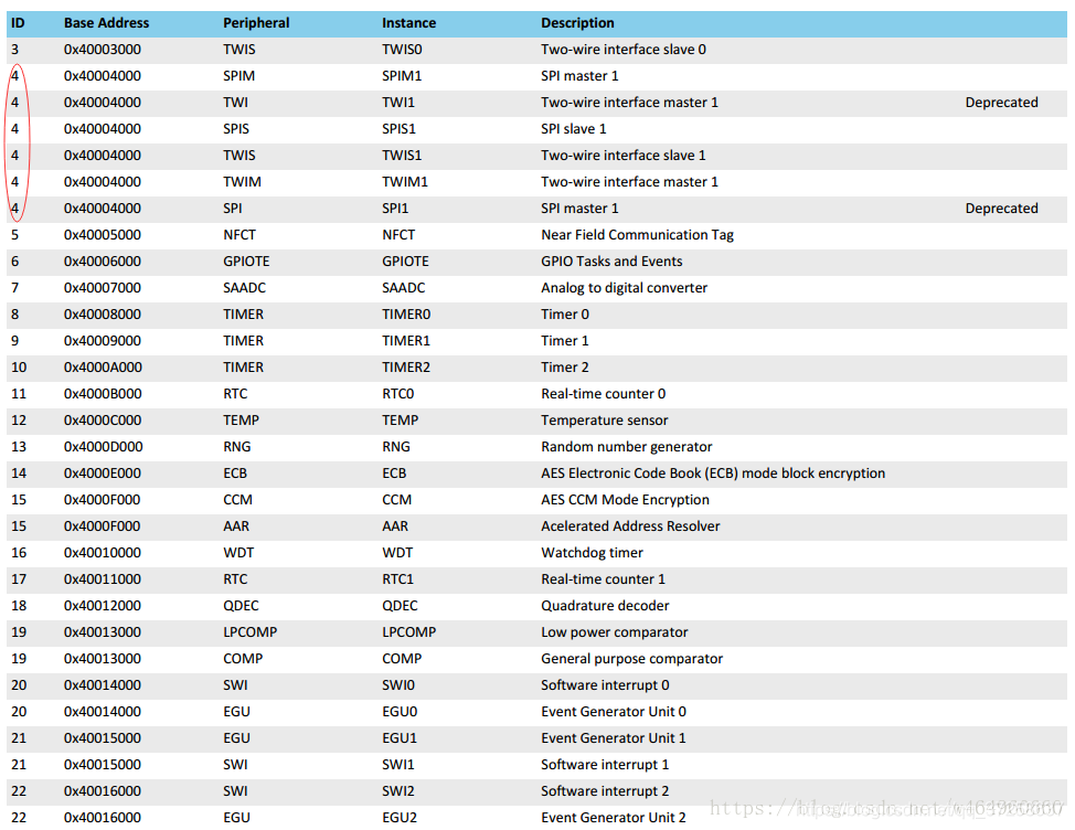
若要避免,有两个方法
1、使用不同ID外设
2、使用模拟SPI或模拟IIC
nRF SPI 初始化
sdk_config.h 中:
添加:
// <h> Application

//==========================================================
// <h> SPI_CONFIGURATION - Spi configuration

//==========================================================
// <o> SPI_BMI088_SCK_PIN - Pin number

// <0=> 0 (P0.0)
// <1=> 1 (P0.1)
// <2=> 2 (P0.2)
// <3=> 3 (P0.3)
// <4=> 4 (P0.4)
// <5=> 5 (P0.5)
// <6=> 6 (P0.6)
// <7=> 7 (P0.7)
// <8=> 8 (P0.8)
// <9=> 9 (P0.9)
// <10=> 10 (P0.10)
// <11=> 11 (P0.11)
// <12=> 12 (P0.12)
// <13=> 13 (P0.13)
// <14=> 14 (P0.14)
// <15=> 15 (P0.15)
// <16=> 16 (P0.16)
// <17=> 17 (P0.17)
// <18=> 18 (P0.18)
// <19=> 19 (P0.19)
// <20=> 20 (P0.20)
// <21=> 21 (P0.21)
// <22=> 22 (P0.22)
// <23=> 23 (P0.23)
// <24=> 24 (P0.24)
// <25=> 25 (P0.25)
// <26=> 26 (P0.26)
// <27=> 27 (P0.27)
// <28=> 28 (P0.28)
// <29=> 29 (P0.29)
// <30=> 30 (P0.30)
// <31=> 31 (P0.31)
// <32=> 32 (P1.0)
// <33=> 33 (P1.1)
// <34=> 34 (P1.2)
// <35=> 35 (P1.3)
// <36=> 36 (P1.4)
// <37=> 37 (P1.5)
// <38=> 38 (P1.6)
// <39=> 39 (P1.7)
// <40=> 40 (P1.8)
// <41=> 41 (P1.9)
// <42=> 42 (P1.10)
// <43=> 43 (P1.11)
// <44=> 44 (P1.12)
// <45=> 45 (P1.13)
// <46=> 46 (P1.14)
// <47=> 47 (P1.15)
// <4294967295=> Not connected

#ifndef SPI_BMI088_SCK_PIN
#define SPI_BMI088_SCK_PIN 45
#endif

// <o> SPI_BMI088_MISO_PIN - Pin number

// <0=> 0 (P0.0)
// <1=> 1 (P0.1)
// <2=> 2 (P0.2)
// <3=> 3 (P0.3)
// <4=> 4 (P0.4)
// <5=> 5 (P0.5)
// <6=> 6 (P0.6)
// <7=> 7 (P0.7)
// <8=> 8 (P0.8)
// <9=> 9 (P0.9)
// <10=> 10 (P0.10)
// <11=> 11 (P0.11)
// <12=> 12 (P0.12)
// <13=> 13 (P0.13)
// <14=> 14 (P0.14)
// <15=> 15 (P0.15)
// <16=> 16 (P0.16)
// <17=> 17 (P0.17)
// <18=> 18 (P0.18)
// <19=> 19 (P0.19)
// <20=> 20 (P0.20)
// <21=> 21 (P0.21)
// <22=> 22 (P0.22)
// <23=> 23 (P0.23)
// <24=> 24 (P0.24)
// <25=> 25 (P0.25)
// <26=> 26 (P0.26)
// <27=> 27 (P0.27)
// <28=> 28 (P0.28)
// <29=> 29 (P0.29)
// <30=> 30 (P0.30)
// <31=> 31 (P0.31)
// <32=> 32 (P1.0)
// <33=> 33 (P1.1)
// <34=> 34 (P1.2)
// <35=> 35 (P1.3)
// <36=> 36 (P1.4)
// <37=> 37 (P1.5)
// <38=> 38 (P1.6)
// <39=> 39 (P1.7)
// <40=> 40 (P1.8)
// <41=> 41 (P1.9)
// <42=> 42 (P1.10)
// <43=> 43 (P1.11)
// <44=> 44 (P1.12)
// <45=> 45 (P1.13)
// <46=> 46 (P1.14)
// <47=> 47 (P1.15)
// <4294967295=> Not connected

#ifndef SPI_BMI088_MISO_PIN
#define SPI_BMI088_MISO_PIN 47
#endif

// <o> SPI_BMI088_MOSI_PIN - Pin number

// <0=> 0 (P0.0)
// <1=> 1 (P0.1)
// <2=> 2 (P0.2)
// <3=> 3 (P0.3)
// <4=> 4 (P0.4)
// <5=> 5 (P0.5)
// <6=> 6 (P0.6)
// <7=> 7 (P0.7)
// <8=> 8 (P0.8)
// <9=> 9 (P0.9)
// <10=> 10 (P0.10)
// <11=> 11 (P0.11)
// <12=> 12 (P0.12)
// <13=> 13 (P0.13)
// <14=> 14 (P0.14)
// <15=> 15 (P0.15)
// <16=> 16 (P0.16)
// <17=> 17 (P0.17)
// <18=> 18 (P0.18)
// <19=> 19 (P0.19)
// <20=> 20 (P0.20)
// <21=> 21 (P0.21)
// <22=> 22 (P0.22)
// <23=> 23 (P0.23)
// <24=> 24 (P0.24)
// <25=> 25 (P0.25)
// <26=> 26 (P0.26)
// <27=> 27 (P0.27)
// <28=> 28 (P0.28)
// <29=> 29 (P0.29)
// <30=> 30 (P0.30)
// <31=> 31 (P0.31)
// <32=> 32 (P1.0)
// <33=> 33 (P1.1)
// <34=> 34 (P1.2)
// <35=> 35 (P1.3)
// <36=> 36 (P1.4)
// <37=> 37 (P1.5)
// <38=> 38 (P1.6)
// <39=> 39 (P1.7)
// <40=> 40 (P1.8)
// <41=> 41 (P1.9)
// <42=> 42 (P1.10)
// <43=> 43 (P1.11)
// <44=> 44 (P1.12)
// <45=> 45 (P1.13)
// <46=> 46 (P1.14)
// <47=> 47 (P1.15)
// <4294967295=> Not connected

#ifndef SPI_BMI088_MOSI_PIN
#define SPI_BMI088_MOSI_PIN 46
#endif


// <o> SPI_BMI088_SS_PIN - Pin number

// <0=> 0 (P0.0)
// <1=> 1 (P0.1)
// <2=> 2 (P0.2)
// <3=> 3 (P0.3)
// <4=> 4 (P0.4)
// <5=> 5 (P0.5)
// <6=> 6 (P0.6)
// <7=> 7 (P0.7)
// <8=> 8 (P0.8)
// <9=> 9 (P0.9)
// <10=> 10 (P0.10)
// <11=> 11 (P0.11)
// <12=> 12 (P0.12)
// <13=> 13 (P0.13)
// <14=> 14 (P0.14)
// <15=> 15 (P0.15)
// <16=> 16 (P0.16)
// <17=> 17 (P0.17)
// <18=> 18 (P0.18)
// <19=> 19 (P0.19)
// <20=> 20 (P0.20)
// <21=> 21 (P0.21)
// <22=> 22 (P0.22)
// <23=> 23 (P0.23)
// <24=> 24 (P0.24)
// <25=> 25 (P0.25)
// <26=> 26 (P0.26)
// <27=> 27 (P0.27)
// <28=> 28 (P0.28)
// <29=> 29 (P0.29)
// <30=> 30 (P0.30)
// <31=> 31 (P0.31)
// <32=> 32 (P1.0)
// <33=> 33 (P1.1)
// <34=> 34 (P1.2)
// <35=> 35 (P1.3)
// <36=> 36 (P1.4)
// <37=> 37 (P1.5)
// <38=> 38 (P1.6)
// <39=> 39 (P1.7)
// <40=> 40 (P1.8)
// <41=> 41 (P1.9)
// <42=> 42 (P1.10)
// <43=> 43 (P1.11)
// <44=> 44 (P1.12)
// <45=> 45 (P1.13)
// <46=> 46 (P1.14)
// <47=> 47 (P1.15)
// <4294967295=> Not connected

#ifndef SPI_BMI088_SS_PIN
#define SPI_BMI088_SS_PIN 8
#endif


// <o> SPI_IRQ_PRIORITY - Interrupt priority

// <i> Priorities 0,2 (nRF51) and 0,1,4,5 (nRF52) are reserved for SoftDevice
// <0=> 0 (highest)
// <1=> 1
// <2=> 2
// <3=> 3
// <4=> 4
// <5=> 5
// <6=> 6
// <7=> 7

#ifndef SPI_IRQ_PRIORITY
#define SPI_IRQ_PRIORITY 2
#endif

// </h>
//==========================================================
勾选:
nRF_Drivers --> NRFX_SPIM_ENABLED
nRF_Drivers --> NRFX_SPI_ENABLED
nRF_Drivers --> SPI_ENABLED
nRF_Drivers --> SPI_ENABLED --> SPI0_ENABLED
nRF_Drivers --> SPI_ENABLED --> SPI0_ENABLED --> SPI0_USE_EASY_DMA
注:
记得打开 SPI0_USE_EASY_DMA,SPI 读写不占用MCU资源,大大提高效率,
nrf_drv_spi.h 中:
#define NRF_DRV_SPI_DEFAULT_CONFIG \
{ \
.sck_pin = NRF_DRV_SPI_PIN_NOT_USED, \
.mosi_pin = NRF_DRV_SPI_PIN_NOT_USED, \
.miso_pin = NRF_DRV_SPI_PIN_NOT_USED, \
.ss_pin = NRF_DRV_SPI_PIN_NOT_USED, \
.irq_priority = SPI_DEFAULT_CONFIG_IRQ_PRIORITY, \
.orc = 0xFF, \
.frequency = NRF_DRV_SPI_FREQ_8M, \
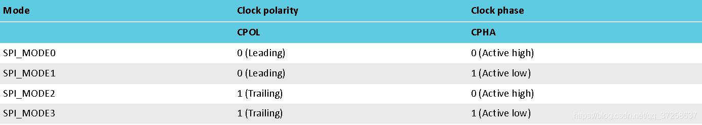
.mode = NRF_DRV_SPI_MODE_0, \
.bit_order = NRF_DRV_SPI_BIT_ORDER_MSB_FIRST, \
}注:
1、设定的 spi 模式,要与传感器对应
2、设定的 spi 的频率要在传感器支持的频率范围内
3、设定的 bit_order 要与传感器的数据排序一致,MSB_FIRST or LSB_FIRST
main.c 中:
#define SPI_INSTANCE_0                  0                                           /**< SPI instance index. */

static const nrf_drv_spi_t spi_0_bmi088 = NRF_DRV_SPI_INSTANCE(SPI_INSTANCE_0);            /**< SPI instance. */

static void spi_bmi088_event_handler(nrf_drv_spi_evt_t const * p_event,
                              					void *                    p_context)
{
    spi_bmi088_xfer_done = true;
//    NRF_LOG_INFO("Spi bmi088 transfer completed.");
}

static void spi_bmi088_init(void)
{
    nrf_drv_spi_config_t spi_bmi088_config = NRF_DRV_SPI_DEFAULT_CONFIG;
    spi_bmi088_config.ss_pin   = NRF_DRV_SPI_PIN_NOT_USED;
    spi_bmi088_config.miso_pin = SPI_BMI088_MISO_PIN;
    spi_bmi088_config.mosi_pin = SPI_BMI088_MOSI_PIN;
    spi_bmi088_config.sck_pin  = SPI_BMI088_SCK_PIN;
    APP_ERROR_CHECK(nrf_drv_spi_init(&spi_0_bmi088, &spi_bmi088_config, spi_bmi088_event_handler, NULL));
}
注:
1、若 cs 片选引脚信号为高使能,或需要操控多个 cs 片选脚时,需在设置时将 .ss_pin 参数留空,另外将其设为输出脚并将其拉高(拉低),在发送或接收时拉低(拉高)。(因为nRF SPI 底层驱动库仅支持 cs 片选引脚低使能)
///< Slave Select pin number (optional).
/**< Set to @ref NRF_DRV_SPI_PIN_NOT_USED
* if this signal is not needed. The driver
* supports only active low for this signal.
* If the signal should be active high,
* it must be controlled externally. */
2、nrf_drv_spi_init 初始化参数中,若回调函数留空则将以阻塞模式执行传输。 Event handler provided by the user. If NULL, transfers will be performed in blocking mode.
nRF 的 SPI 发送与接收做成了一体,收发都需要调用 nrf_drv_spi_transfer:
1、做发送时
nrf_drv_spi_transfer(&spi_0_bmi088, m_tx_buf, m_tx_length, NULL, 0)
发送的数据 m_tx_buf 内容为 :
m_tx_buf[0] = reg_addr
memcpy(&m_tx_buf[1], data, len);
首字节为寄存器地址,(注:需要做偏移,例如,最高位读写位为0时为写,则需 & 0x7F
从第二个字节开始为要写入的数据)
发送的数据长度 m_tx_length
必须是写入数据的长度 + 1(寄存器地址)
接收BUF及接收数据长度留空
2、做接收时
nrf_drv_spi_transfer(&spi_0_bmi088, m_tx_buf, m_tx_length, data, m_rx_length)
发送的数据 m_tx_buf 内容为 :
uint8_t m_tx_buf[1] = {reg_addr};
首字节为寄存器地址,(注:需要做偏移,例如,最高位读写位为1时为读,则需 | 0x80
从第二个字节开始为要写入的数据)
发送的数据长度 m_tx_length = 1;
接收数据长度根据数据而定
注:特别注意冗余数据处理,(具体参考2_Vibration_measurer-Github 项目)=
例:
/*!
 *  @brief Function for reading the sensor's registers through SPI bus.
 *
 *  @param[in] cs_pin   : Chip selection pin.
 *  @param[in] reg_addr : Register address.
 *  @param[in] data     : Pointer to the data buffer to store the read data.
 *  @param[in] len      : No of bytes to read.
 *
 *  @return Status of execution
 *  @retval 0 -> Success
 *  @retval >0 -> Failure Info
 *
 */
int8_t user_bmi088_spi_write(uint8_t cs_pin, uint8_t reg_addr, uint8_t *data, uint16_t len)
{
    if (cs_pin == MCU_GPIO_BMI088_CSB1)
    {
        nrf_gpio_pin_set(MCU_GPIO_BMI088_CSB2);
        nrf_gpio_pin_clear(MCU_GPIO_BMI088_CSB1);
    }
    else if (cs_pin == MCU_GPIO_BMI088_CSB2)
    {
        nrf_gpio_pin_set(MCU_GPIO_BMI088_CSB1);
        nrf_gpio_pin_clear(MCU_GPIO_BMI088_CSB2);
    }
    else
    {
        return -2;
    }

    nrf_delay_us(1);

    if (len <= 32)
    {
        uint8_t m_tx_buf[33] = {0};
        m_tx_buf[0] = reg_addr;
        uint8_t m_tx_length = ((uint8_t)len) + 1;
        memcpy(&m_tx_buf[1], data, len);

        spi_bmi088_xfer_done = false;
        APP_ERROR_CHECK(nrf_drv_spi_transfer(&spi_0_bmi088, m_tx_buf, m_tx_length, NULL, 0));
        while(spi_bmi088_xfer_done == false)
        {
            __WFE();
        }
    }
    else
    {
        NRF_LOG_INFO("Spi write over length.");
    }

    nrf_delay_us(1);
    nrf_gpio_pin_set(MCU_GPIO_BMI088_CSB1);
    nrf_gpio_pin_set(MCU_GPIO_BMI088_CSB2);

    return 0;
}


/*!
 *  @brief Function for writing the sensor's registers through SPI bus.
 *
 *  @param[in] cs_pin   : Chip selection pin.
 *  @param[in] reg_addr : Register address.
 *  @param[out]data     : Pointer to the data buffer whose value is to be written.
 *  @param[in] len      : No of bytes to write.
 *
 *  @return Status of execution
 *  @retval 0 -> Success
 *  @retval >0 -> Failure Info
 *
 */
int8_t user_bmi088_spi_read(uint8_t cs_pin, uint8_t reg_addr, uint8_t *data, uint16_t len)
{
    if (cs_pin == MCU_GPIO_BMI088_CSB1)
    {
        nrf_gpio_pin_set(MCU_GPIO_BMI088_CSB2);
        nrf_gpio_pin_clear(MCU_GPIO_BMI088_CSB1);
    }
    else if (cs_pin == MCU_GPIO_BMI088_CSB2)
    {
        nrf_gpio_pin_set(MCU_GPIO_BMI088_CSB1);
        nrf_gpio_pin_clear(MCU_GPIO_BMI088_CSB2);
    }
    else
    {
        return -2;
    }

    nrf_delay_us(1);

    if (len <= 32)
    {
        uint8_t m_tx_buf[1] = {reg_addr};
        uint8_t m_tx_length = 1;
        uint8_t m_rx_length = (uint8_t)len + 1; // Add the byte sent
        uint8_t m_rx_buf[33] = {0};

        spi_bmi088_xfer_done = false;
        APP_ERROR_CHECK(nrf_drv_spi_transfer(&spi_0_bmi088, m_tx_buf, m_tx_length, m_rx_buf, m_rx_length));
        while(spi_bmi088_xfer_done == false)
        {
            __WFE();
        }

        memcpy(data, &m_rx_buf[1], (m_rx_length - 1));
    }
    else
    {
        NRF_LOG_INFO("Spi read over length.");
    }

    nrf_delay_us(1);
    nrf_gpio_pin_set(MCU_GPIO_BMI088_CSB1);
    nrf_gpio_pin_set(MCU_GPIO_BMI088_CSB2);

    return 0;
}
nRF TWI 初始化
sdk_config.h 中:
勾选:
NRFX_TWIM_ENABLED --> NRFX_TWIM_ENABLED
NRFX_TWIM_ENABLED --> NRFX_TWI_ENABLED
NRFX_TWIM_ENABLED --> NRFX_TWI_ENABLED --> TWI1_ENABLED
NRFX_TWIM_ENABLED --> NRFX_TWI_ENABLED --> TWI1_ENABLED -->TWI1_USE_EASY_DMA
修改:
TWI_DEFAULT_CONFIG_FREQUENCY 26738688
TWI_DEFAULT_CONFIG_CLR_BUS_INIT 0
TWI_DEFAULT_CONFIG_HOLD_BUS_UNINIT 0
TWI_DEFAULT_CONFIG_IRQ_PRIORITY 2
nrf_drv_twi.h 中:
#define NRF_DRV_TWI_DEFAULT_CONFIG                                               \
{                                                                                \
    .frequency          = (nrf_drv_twi_frequency_t)TWI_DEFAULT_CONFIG_FREQUENCY, \
    .scl                = 0xFF,                                                  \
    .sda                = 0xFF,                                                  \
    .interrupt_priority = TWI_DEFAULT_CONFIG_IRQ_PRIORITY,                       \
    .clear_bus_init     = TWI_DEFAULT_CONFIG_CLR_BUS_INIT,                       \
    .hold_bus_uninit    = TWI_DEFAULT_CONFIG_HOLD_BUS_UNINIT,                    \
}
main.c 中:
static void twi_mlx90614_handler(nrf_drv_twi_evt_t const * p_event, void * p_context)
{
    switch (p_event->type)
    {
        case NRF_DRV_TWI_EVT_DONE:
        {
            if (p_event->xfer_desc.type == NRF_DRV_TWI_XFER_TX)
            {
                NRF_LOG_INFO("Twi mlx90614 tx evt done.");
            }
            else if (p_event->xfer_desc.type == NRF_DRV_TWI_XFER_RX)
            {
                NRF_LOG_INFO("Twi mlx90614 rx evt done.");
            }
            else if (p_event->xfer_desc.type == NRF_DRV_TWI_XFER_TXRX)
            {
                NRF_LOG_INFO("Twi mlx90614 txrx evt done.");
            }
            else if (p_event->xfer_desc.type == NRF_DRV_TWI_XFER_TXTX)
            {
                NRF_LOG_INFO("Twi mlx90614 txtx evt done.");
            }
            twi_mlx90614_xfer_done = true;
        } break;

        case NRF_DRV_TWI_EVT_ADDRESS_NACK:
            NRF_LOG_ERROR("Error event: NACK received after sending the address.");
            break;

        case NRF_DRV_TWI_EVT_DATA_NACK:
            NRF_LOG_ERROR("Error event: NACK received after sending a data byte.");
        break;

        default:
            break;
    }
}


static void twi_mlx90614_init(void)
{
    ret_code_t err_code;

    nrf_drv_twi_config_t twi_mlx90614_config = NRF_DRV_TWI_DEFAULT_CONFIG;
    twi_mlx90614_config.scl                  = TWI_MLX90614_SCL_PIN,
    twi_mlx90614_config.sda                  = TWI_MLX90614_SDA_PIN,

    err_code = nrf_drv_twi_init(&twi_1_mlx90614, &twi_mlx90614_config, twi_mlx90614_handler, NULL);
APP_ERROR_CHECK(err_code);

    nrf_drv_twi_enable(&twi_1_mlx90614);
}
nRF 的 TWI 发送调用 nrf_drv_twi_tx,接收调用 nrf_drv_twi_rx。具体时序依照传感器数据手册
例如 mlx90614:
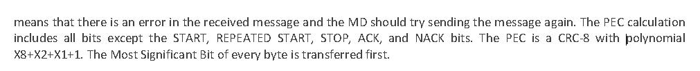
uint8_t PEC_Calculation(uint8_t pec[])
{
    uint8_t crc[6];
    uint8_t BitPosition = 47;
    uint8_t shift;
    uint8_t i;
    uint8_t j;
    uint8_t temp;

    do
    {
        /*Load pattern value 0x000000000107*/
        crc[5] = 0;
        crc[4] = 0;
        crc[3] = 0;
        crc[2] = 0;
        crc[1] = 0x01;
        crc[0] = 0x07;

        /*Set maximum bit position at 47 ( six bytes byte5...byte0,MSbit=47)*/
        BitPosition = 47;

        /*Set shift position at 0*/
        shift = 0;

        /*Find first "1" in the transmited message beginning from the MSByte byte5*/
        i = 5;
        j = 0;
        while (((pec[i] & (0x80 >> j)) == 0) && (i > 0))
        {
            BitPosition--;
            if (j < 7)
            {
                j++;
            }
            else
            {
                j = 0x00;
                i--;
            }
        }/*End of while */

        /*Get shift value for pattern value*/
        shift = BitPosition - 8;

        /*Shift pattern value */
        while(shift)
        {
            for(i = 5; i < 0xFF; i--)
            {
                if((crc[i-1] & 0x80) && (i > 0))
                {
                    temp = 1;
                }
                else
                {
                    temp = 0;
                }
                crc[i] <<= 1;
                crc[i] += temp;
            }/*End of for*/
            shift--;
        }/*End of while*/

        /*Exclusive OR between pec and crc*/
        for(i = 0; i <= 5; i++)
        {
            pec[i] ^= crc[i];
        }/*End of for*/
    } while(BitPosition > 8); /*End of do-while*/

    return pec[0];
}


uint16_t SMBus_Read_Memory(uint8_t slave_Address, uint8_t command)
{
    ret_code_t err_code;
    uint16_t data;			// Data storage (DataH:DataL)
    uint8_t Pec;			// PEC byte storage
    uint8_t PecReg;			// Calculated PEC byte storage
    uint8_t arr[6];			// Buffer for the sent bytes
    uint8_t DataL = 0;			// Low data byte storage
    uint8_t DataH = 0;			// High data byte storage
    uint8_t Error_Counter;              // Defines the number of the attempts for communication with MLX90614
    uint8_t rx_data[3] = {0};           // Data received from twi
    uint8_t tx_data[1] = {command};     // Data sent from twi

    Error_Counter = 0x00;               // Initialising of Error_Counter
    slave_Address <<= 1;                // 2-7 bits indicate the slave address

    do
    {
        err_code = nrf_drv_twi_tx(&twi_1_mlx90614, slave_Address, tx_data, 1, true);
        APP_ERROR_CHECK(err_code);
        twi_mlx90614_xfer_done = false;
        while(twi_mlx90614_xfer_done == false);
        {
            __WFE();
        }

        err_code = nrf_drv_twi_rx(&twi_1_mlx90614, slave_Address, rx_data, 3);
        APP_ERROR_CHECK(err_code);
        twi_mlx90614_xfer_done = false;
        while(twi_mlx90614_xfer_done == false);
        {
            __WFE();
        }

        DataL = rx_data[0];
        DataH = rx_data[1];
        Pec = rx_data[2];

        arr[5] = slave_Address;
        arr[4] = command;
        arr[3] = slave_Address + 1;
        arr[2] = DataL;
        arr[1] = DataH;
        arr[0] = 0;
        PecReg = PEC_Calculation(arr);  // Calculate CRC
    } while(PecReg != Pec);             // If received and calculated CRC are equal go out from do-while{}

    data = (DataH << 8) | DataL;        // data = DataH:DataL

    return data;
}


static float SMBus_Read_Ambient_Temp(void)
{
    return SMBus_Read_Memory(SA, (RAM_ACCESS | RAM_TA)) * 0.02 - 273.15;
}


static float SMBus_Read_Object_Temp(void)
{
    return SMBus_Read_Memory(SA, (RAM_ACCESS | RAM_TOBJ1)) * 0.02 - 273.15;
}
注:
1、nrf_drv_twi_tx 第五个参数是 是否不发送停止位
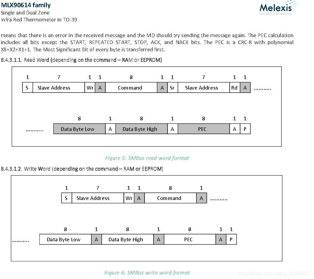
2、如果需要访问EEPROM中的地址,则实际的地址值是需要访问的地址值与 Opcode 的组合
如EEPROM的0x0E地址,实际中输入的应该是0x2E
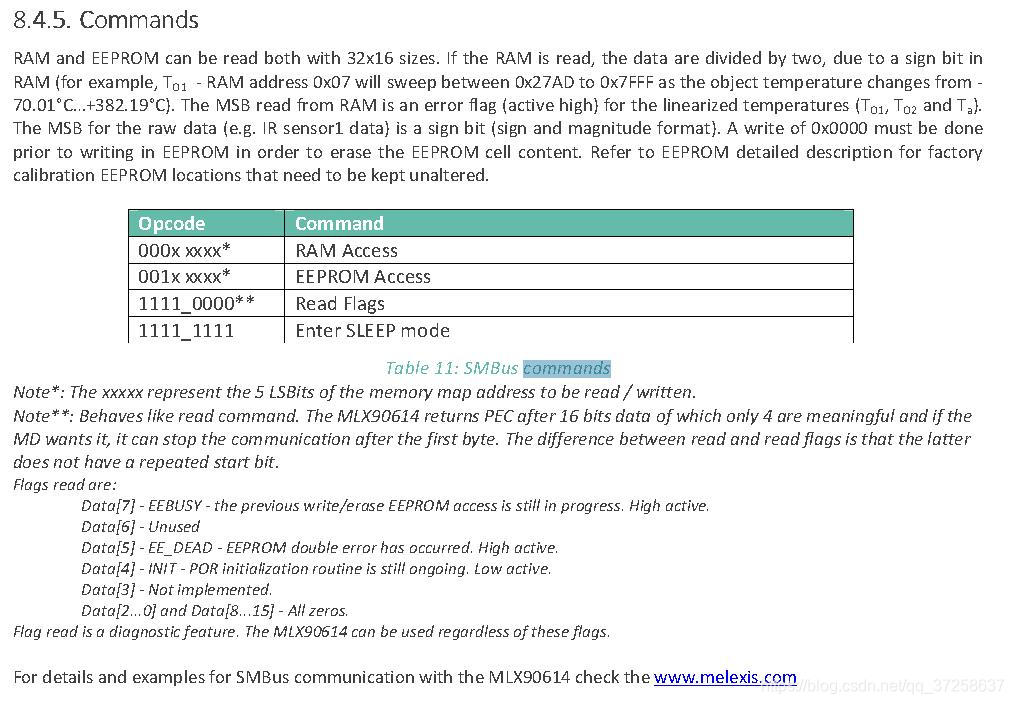
3、写的数据末尾一个字节要加上PEC
4、如果是写数据,先要把寄存器数据清零。比如命令为0x24,也就是修改发射频率,第一次先对高低八位分别写一遍0x00,第二次再重新用这个命令写入你要改的数据。
参考 2_Vibration_measurer-Github 项目


 1万+
1万+


 被折叠的 条评论
为什么被折叠?
被折叠的 条评论
为什么被折叠?
 到【灌水乐园】发言


