


1、腐蚀
先看一下源码参数:
1-1 erode
@param src input image; the number of channels can be arbitrary, but the depth should be one of
CV_8U, CV_16U, CV_16S, CV_32F or CV_64F.
@param dst output image of the same size and type as src.
@param kernel structuring element used for erosion; if `element=Mat()`, a `3 x 3` rectangular
structuring element is used. Kernel can be created using #getStructuringElement.
@param anchor position of the anchor within the element; default value (-1, -1) means that the
anchor is at the element center.
@param iterations number of times erosion is applied.
@param borderType pixel extrapolation method, see #BorderTypes. #BORDER_WRAP is not supported.
@param borderValue border value in case of a constant border
@sa  dilate, morphologyEx, getStructuringElement
 */
CV_EXPORTS_W void erode( InputArray src, OutputArray dst, InputArray kernel,
                         Point anchor = Point(-1,-1), int iterations = 1,
                         int borderType = BORDER_CONSTANT,
                         const Scalar& borderValue = morphologyDefaultBorderValue() );
erode(输入图像,输出图像,蚀刻结构,默认蚀刻矩阵中心,蚀刻迭代次数,略,略,略);
一般只用到前五个参数,后面三个参数分别为蚀刻模式像素外推,与边界类型,最后一个参数返回蚀刻或者膨胀的边界值(后三个参数感兴趣的可以自己研究一下)。
蚀刻因子:kernel,可以使用#getStructuringElement创建内核。
用于侵蚀的核结构元素;如果`element=Mat()`,则为`3 x 3`矩形
anchor:蚀刻结构的锚点,默认为Point(-1,-1),定义为蚀刻结构中心。
1-2 getStructuringElement
CV_EXPORTS_W Mat getStructuringElement(int shape, Size ksize, Point anchor = Point(-1,-1));
关于参数说明:
shape:int型,表示蚀刻图形的形状,参数详情见枚举列表,0为矩形,1为十字交叉形状,2为椭圆
//! shape of the structuring element
enum MorphShapes {
    MORPH_RECT    = 0, //!< a rectangular structuring element:  \f[E_{ij}=1\f]
    MORPH_CROSS   = 1, //!< a cross-shaped structuring element:
                       //!< \f[E_{ij} = \begin{cases} 1 & \texttt{if } {i=\texttt{anchor.y } {or } {j=\texttt{anchor.x}}} \\0 & \texttt{otherwise} \end{cases}\f]
    MORPH_ELLIPSE = 2 //!< an elliptic structuring element, that is, a filled ellipse inscribed
                      //!< into the rectangle Rect(0, 0, esize.width, 0.esize.height)
};
ksize():Mat类型,表示蚀刻矩阵尺寸
anchor:Point()类型,为蚀刻矩阵的权重点(锚点),默认(-1,-1)为矩阵中心位置。只有十字形元素的形状取决于锚点位置。在其他情况下,锚点不同只会造成结果的大小偏移。
返回值:Mat类型,一般定义一个Mat对象去接受蚀刻因子,在使用时直接传递给erode(srcimg, erodesrc, element);
1-3 示例
    Mat srcimg = (...);//原图,自己读取或者绘制一个图像都行
    Mat erodesrc;//蚀刻后图像

//定义一个3*3,中心为(1,1)的蚀刻结构元素
    int g_nStructElementSize = 3;

    Mat element = getStructuringElement(MORPH_RECT, Size(2 * g_nStructElementSize + 1, 2 * g_nStructElementSize + 1), Point(g_nStructElementSize, g_nStructElementSize));

    erode(srcimg, erodesrc, element);


/*
此时打印矩阵的结果为
element:
1 1 1 1 1 1 1
1 1 1 1 1 1 1
1 1 1 1 1 1 1
1 1 1 1 1 1 1
1 1 1 1 1 1 1
1 1 1 1 1 1 1
1 1 1 1 1 1 1

*/
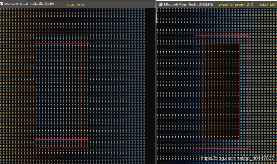
在50*80的底图上绘制18*41的矩形(白色矩形),用siz(7*7),point(3,3)的结构元素去蚀刻;可以看到,以蚀刻元素(3,3)位置为中心,沿矩形边界走一圈,当结构元素中所有点(矩阵)均落在矩形内时,蚀刻结构元素的中心点被保留,当沿矩形轮廓一圈结束后,保留的中心点之外的所有点被蚀刻;蚀刻后矩形为尺寸为12*35;

1-4 扩展
蚀刻结构也可以自定义,由getStructuringElement函数可以知道,其返回值类型为Mat,时刻类型为矩阵结构,所以我们只需要定义一个Mat矩阵即可
Mat srcimg = (...);//原图,自己读取或者绘制一个图像都行
Mat erodesrc;//蚀刻后图像
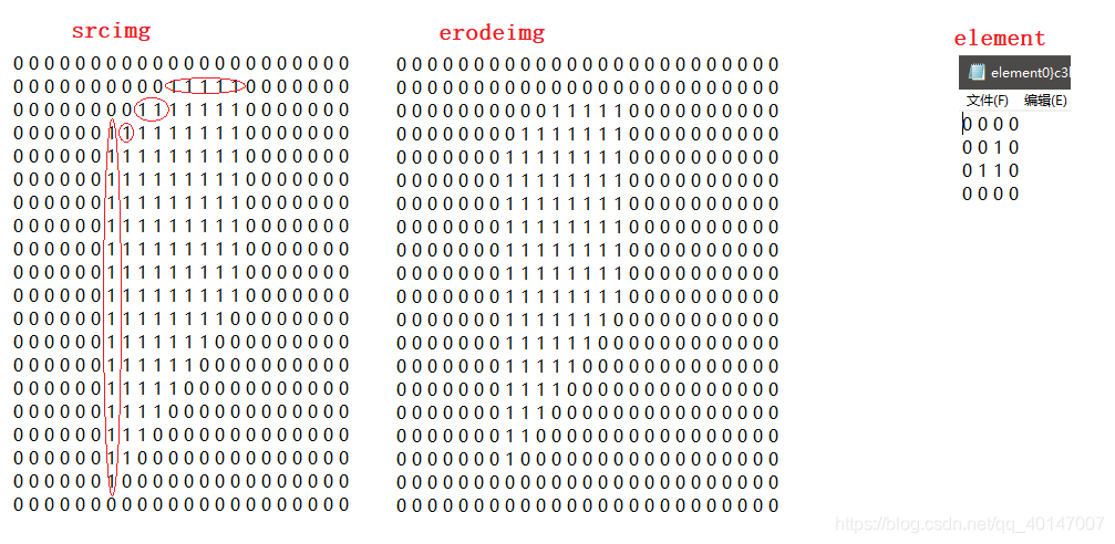
Mat element = (Mat_<uchar>(4,4)<<0,0,0,0,0,0,1,0,0,1,1,0,0,0,0,0);//自定义蚀刻矩阵
erode(srcimg, erodesrc, element);
/*
element:
0 0 0 0
0 0 1 0
0 1 1 0
0 0 0 0
*/对比蚀刻前后发现,凡是中心点之外的像素均被蚀刻掉,经过多次调整anchor锚点发现,在矩形MORPH_RECT蚀刻模式下,锚点调整对结果无影响;在自定义蚀刻矩阵下,调整锚点对结果无影响。
2、膨胀
膨胀后续补充,跟蚀刻一样的道理;
图像上的腐蚀与膨胀都是针对白色像素范围的对象进行操作,操作图像为二值化图像,所以在目标对象为黑色填充是可能会取得相反的效果;
实际图像蚀刻尺寸过小不易对比,在vs2017下可以用image watch插件查看,或者将图像像素以0,1方式打印出来,便于对比
//model   1:print element       2 or other:print img
void ImgToNumber(Mat img, const char* filename, int model) {
	string path = "\\";  //文件保存路径
	path += filename;
	path += ".png";
	fstream fp(path.c_str(), ios::out);
	if (model == 1) {
		for (int row = 0; row < img.rows; row++)
		{
			for (int col = 0; col < img.cols; col++)
			{
				//注意 Mat是单道的图,类型为CV_8UC1
				fp << (int)img.at<uchar>(row, col) << " ";
			}
			fp << "\n";
		}
	}
	else {
		for (int row = 0; row < img.rows; row++)
		{
			for (int col = 0; col < img.cols; col++)
			{
				if (img.at<uchar>(row, col) > 128) {
					fp << 1 << " ";
				}
				else
					fp << 0 << " ";
			}
			fp << "\n";
		}
	}
	fp.close();
}
另外有一点疑惑,opencv line();函数在绘线时,thickness,线宽在偶数值时结果达不到预期值,好像只支持奇数宽度,尝试宽度为 1 2 3 4 5 宽度时得到的实际宽度为 1 3 3 5 5
opencv 3.4.12 && vs2017


 1094
1094


 被折叠的 条评论
为什么被折叠?
被折叠的 条评论
为什么被折叠?
 到【灌水乐园】发言


