


board_init_r函数分析
重定向完成后,lr就会跳转到board_init_r函数处开始执行下半部分板子的初始化。
(1)将重定位后的gd还是放在r8寄存器里边,给gd->flags赋值
gd=id;
gd->flags|=GD_FLG_RELOC;
(2)enable_caches();(位于uboot/arch/arm/lib/Cache.c)
->
__enable_caches(void)
->
puts(“WARNING: Caches not
enabled\n”);
实际上并没有真正对cache进行操作,只是打印了一下:"WARNING: Caches not enabled”。
(3)板级初始化 board_init();(位于\uboot\board\davinci\da8xxevm目录下)
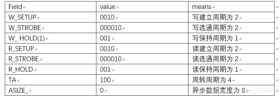
#define DAVINCI_ABCR_STROBE_SELECT               (1 << 31)

#define DAVINCI_ABCR_EXT_WAIT                        (1 << 30)

#define DAVINCI_ABCR_WSETUP(n)                       (n << 26)

#define DAVINCI_ABCR_WSTROBE(n)                           (n << 20)

#define DAVINCI_ABCR_WHOLD(n)                       (n << 17)

#define DAVINCI_ABCR_RSETUP(n)                        (n << 13)

#define DAVINCI_ABCR_RSTROBE(n)                      (n << 7)

#define DAVINCI_ABCR_RHOLD(n)                        (n << 4)

#define DAVINCI_ABCR_TA(n)                         (n << 2)

#define DAVINCI_ABCR_ASIZE_16BIT              1

#define DAVINCI_ABCR_ASIZE_8BIT                       0


1)
writel((DAVINCI_ABCR_WSETUP(2)
|

              DAVINCI_ABCR_WSTROBE(2)
|

              DAVINCI_ABCR_WHOLD(1)
|

              DAVINCI_ABCR_RSETUP(2)
|

              DAVINCI_ABCR_RSTROBE(2)
|

              DAVINCI_ABCR_RHOLD(1)
|

              DAVINCI_ABCR_TA(1)
|

              DAVINCI_ABCR_ASIZE_8BIT),

              &davinci_emif_regs->ab2cr); /*CS3 */

)))
/* arch number of the board */
2 )
gd->bd->bi_arch_number =MACH_TYPE_DAVINCI_DA850_EVM;
/* address of boot parameters */
MACH_TYPE_DAVINCI_DA850_EVM=2157
3 ) gd->bd->bi_boot_params= LINUX_BOOT_PARAM_ADDR;
->
#define LINUX_BOOT_PARAM_ADDR (PHYS_SDRAM_1 + 0x100)
->
#define PHYS_SDRAM_1 DAVINCI_DDR_EMIF_DATA_BASE /* DDR Start */
->
#define DAVINCI_DDR_EMIF_DATA_BASE 0xc0000000
最后得到:LINUX_BOOT_PARAM_ADDR =0xc0000100
4 ) /*
setup the SUSPSRC for ARM to control emulation suspend */
writel(readl(&davinci_syscfg_regs->suspsrc)
&

              ~(DAVINCI_SYSCFG_SUSPSRC_EMAC |
DAVINCI_SYSCFG_SUSPSRC_I2C |

               DAVINCI_SYSCFG_SUSPSRC_SPI1 |
DAVINCI_SYSCFG_SUSPSRC_TIMER0 |

               DAVINCI_SYSCFG_SUSPSRC_UART2),

              &davinci_syscfg_regs->suspsrc);


/* Emulation suspend bits */

#define DAVINCI_SYSCFG_SUSPSRC_EMAC            (1 << 5)

#define DAVINCI_SYSCFG_SUSPSRC_I2C         (1 << 16)

#define DAVINCI_SYSCFG_SUSPSRC_SPI0       (1 << 21)

#define DAVINCI_SYSCFG_SUSPSRC_SPI1       (1 << 22)

#define DAVINCI_SYSCFG_SUSPSRC_UART0           (1 << 18)

#define DAVINCI_SYSCFG_SUSPSRC_UART2           (1 << 20)

#define DAVINCI_SYSCFG_SUSPSRC_TIMER0         (1 << 27)
上述设置表明,EMAC,I2C,SPI0,SPI1,UART0,UART2,TIMER0的仿真暂停是由arm来控制的。
5 ) /* configure pinmux settings */
if(davinci_configure_pin_mux_items(pinmuxes, ARRAY_SIZE(pinmuxes)))

              return 1;

->(位于\uboot\board\davinci\da8xxevm\目录下)

const struct pinmux_resource pinmuxes[] = {

#ifdef CONFIG_DRIVER_TI_EMAC

       PINMUX_ITEM(emac_pins_mdio),

#ifdef CONFIG_DRIVER_TI_EMAC_USE_RMII

       PINMUX_ITEM(emac_pins_rmii),

#else

       PINMUX_ITEM(emac_pins_mii),

#endif

#endif

#ifdef CONFIG_SPI_FLASH

       PINMUX_ITEM(spi1_pins_base),

       PINMUX_ITEM(spi1_pins_scs0),

#endif

       PINMUX_ITEM(uart2_pins_txrx),

/*    PINMUX_ITEM(uart2_pins_rtscts),
*/

       PINMUX_ITEM(i2c0_pins),

#ifdef CONFIG_NAND_DAVINCI

       PINMUX_ITEM(emifa_pins_cs0),

       PINMUX_ITEM(emifa_pins_cs2),

       PINMUX_ITEM(emifa_pins_cs3),

       PINMUX_ITEM(emifa_pins_cs4),

       PINMUX_ITEM(emifa_pins_cs5),

       PINMUX_ITEM(emifa_pins_nand),

#elif defined(CONFIG_USE_NOR)

       PINMUX_ITEM(emifa_pins_cs2),

       PINMUX_ITEM(emifa_pins_nor),

#endif

       PINMUX_ITEM(gpio_pins),

       PINMUX_ITEM(clkout_pins),

#ifdef CONFIG_DAVINCI_MMC

       PINMUX_ITEM(mmc0_pins),

#endif

};
跟踪其中一个函数来获得编译的结果
PINMUX_ITEM(emac_pins_mdio),
{
.pins=emac_pings_mdio;
.n_pins=ARRAY_SIZE(emac_pins_mdio)
}
->
davinci_configure_pin_mux_items(const
struct pinmux_resource *item,const int n_items)
->
davinci_configure_pin_mux(item[i].pins, item[i].n_pins)
->
davinci_configure_pin_mux(emac_pings_mdio,2)
->
const
struct pinmux_config emac_pins_mdio[] = {
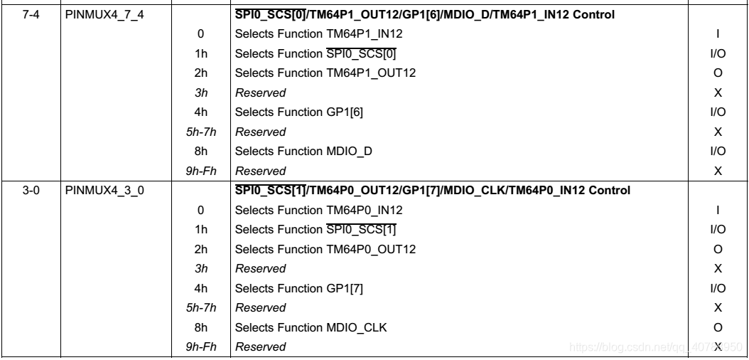
{ pinmux(4), 8, 0 }, /* MDIO_CLK */
{ pinmux(4), 8, 1 }, /* MDIO_D */
};
->
offset=0*4=0;
value=8<<0=8;
mask=(1<<4)-1<<0=1111;
查表可知配置为MDIO_CLK
->
offset=1*4=1;
value=8<<4=1000,0000
make=(1<<4)-1<<4=1111,0000
查表可知配置为MDIO_D
同理可得此处其他管脚复用的配置有:
l  /* EMAC pin muxer settings*/

const struct pinmux_config emac_pins_mii[] = {

       {
pinmux(2), 8, 1 }, /* MII_TXEN */

       {
pinmux(2), 8, 2 }, /* MII_TXCLK */

       {
pinmux(2), 8, 3 }, /* MII_COL */

       {
pinmux(2), 8, 4 }, /* MII_TXD[3] */

       {
pinmux(2), 8, 5 }, /* MII_TXD[2] */

       {
pinmux(2), 8, 6 }, /* MII_TXD[1] */

       {
pinmux(2), 8, 7 }, /* MII_TXD[0] */

       {
pinmux(3), 8, 0 }, /* MII_RXCLK */

       {
pinmux(3), 8, 1 }, /* MII_RXDV */

       {
pinmux(3), 8, 2 }, /* MII_RXER */

       {
pinmux(3), 8, 3 }, /* MII_CRS */

       {
pinmux(3), 8, 4 }, /* MII_RXD[3] */

       {
pinmux(3), 8, 5 }, /* MII_RXD[2] */

       {
pinmux(3), 8, 6 }, /* MII_RXD[1] */

       {
pinmux(3), 8, 7 }, /* MII_RXD[0] */

};


l  /* SPI pin muxer settings */

const struct pinmux_config spi1_pins_base[]
= {

       {
pinmux(5), 1, 2 }, /* SPI1_CLK */

       {
pinmux(5), 1, 4 }, /* SPI1_SOMI */

       {
pinmux(5), 1, 5 }, /* SPI1_SIMO */

};


const struct pinmux_config spi1_pins_scs0[]
= {

       {
pinmux(5), 1, 1 }, /* SPI1_SCS[0] */

};


l  /* UART pin muxer settings */

const struct pinmux_config uart2_pins_txrx[]
= {

       {
pinmux(4), 2, 4 }, /* UART2_RXD */

       {
pinmux(4), 2, 5 }, /* UART2_TXD */

};

l  /* EMIFA pin muxer settings */

const struct pinmux_config emifa_pins_cs0[]
= {

       {
pinmux(6), 1, 7 }, /* EMA_CS0 */

};


const struct pinmux_config emifa_pins_cs2[]
= {

       {
pinmux(7), 1, 0 }, /* EMA_CS2 */

};


const struct pinmux_config emifa_pins_cs3[]
= {

       {
pinmux(7), 1, 1 }, /* EMA_CS[3] */

};


const struct pinmux_config emifa_pins_cs4[]
= {

       {
pinmux(7), 1, 2 }, /* EMA_CS[4] */

};


const struct pinmux_config emifa_pins_cs5[]
= {

       {
pinmux(7), 1, 3 }, /* EMA_CS[5] */

};


const struct pinmux_config
emifa_pins_nand[] = {

       {
pinmux(7), 1, 4 },  /* EMA_WE */

       {
pinmux(7), 1, 5 },  /* EMA_OE */

       {
pinmux(9), 1, 0 },  /* EMA_D[7] */

       {
pinmux(9), 1, 1 },  /* EMA_D[6] */

       {
pinmux(9), 1, 2 },  /* EMA_D[5] */

       {
pinmux(9), 1, 3 },  /* EMA_D[4] */

       {
pinmux(9), 1, 4 },  /* EMA_D[3] */

       {
pinmux(9), 1, 5 },  /* EMA_D[2] */

       {
pinmux(9), 1, 6 },  /* EMA_D[1] */

       {
pinmux(9), 1, 7 },  /* EMA_D[0] */

       {
pinmux(12), 1, 5 }, /* EMA_A[2] */

       {
pinmux(12), 1, 6 }, /* EMA_A[1] */

};


l  #ifdef CONFIG_DAVINCI_MMC

       /*
GP0[11] is required for SD to work on Rev 3 EVMs */

       {
pinmux(0),  8, 4 },     /* GP0[11] */

#endif

       /*
GP6[13] is indicator for SPL to work on TL BOARD */

       {
pinmux(13),  8, 2 },    /* GP6[13] */

       /*
GP6[12] is indicator for U-BOOT to work on TL BOARD */

       {
pinmux(13),  8, 3 },    /* GP6[12] */


       /*
GP0[7] is pwm blacklight for LCD to work on TL BOARD */

       {
pinmux(1),  8, 0 },     /* GP0[7] */

};

l  static const struct pinmux_config clkout_pins[] = {

       /*
PLL_CLKOUT is to work on TL BOARD */

       {
pinmux(13), 1, 1 },      /* PLL_CLKOUT*/

};

l  /* MMC0 pin muxer settings */

const struct pinmux_config mmc0_pins[] = {

       {
pinmux(10), 2, 0 },      /* MMCSD0_CLK */

       {
pinmux(10), 2, 1 },      /* MMCSD0_CMD */

       {
pinmux(10), 2, 2 },      /* MMCSD0_DAT_0
*/

       {
pinmux(10), 2, 3 },      /* MMCSD0_DAT_1
*/

       {
pinmux(10), 2, 4 },      /* MMCSD0_DAT_2
*/

       {
pinmux(10), 2, 5 },      /* MMCSD0_DAT_3
*/

       /*
DA850 supports only 4-bit mode, remaining pins are not configured */

};


 4万+
4万+


 被折叠的 条评论
为什么被折叠?
被折叠的 条评论
为什么被折叠?
 到【灌水乐园】发言


