


 本实验通过STM32最小系统板实现基于MODBUS协议的温湿度数据读取,利用C语言编程完成TCP客户端与服务器之间的通信,并在STM32上构建了一个MODBUS协议的温湿度Slave设备。
重庆交通大学信息科学与工程学院
《嵌入式系统基础A》课程
作业报告(第十二周-第十五周)
班 级: 物联网工程2002班
姓名-学号 : 唐宇轩-632007060411
实验项目名称: 嵌入式RTOS编程
实验项目性质: 设计性
实验所属课程: 《嵌入式系统基础》
实验室(中心): 南岸校区语音大楼
指 导 教 师 : 娄路
完成时间: 2022 年 12 月 26 日
一、实验内容和任务
一、在消化学习 server.c和client.c 套接字代码、python-modbus-over-tcp.py 代码基础上,试着用C编程完成modbus协议,从云端服务器读取温湿度数据。
二、用stm32最小核心板+AHT20模块,完成一个 modbus接口的温湿度Slave设备,能够让上位机PC通过modbus协议获取温湿度。主程序采用多任务框架,比如RT-thread Nano。
二、实验要求
1. 分组要求:每个学生独立完成,即1人1组。
2. 程序及报告文档要求:具有较好的可读性,如叙述准确、标注明确、截图清晰等。
3.项目代码上传github,同时把项目完整打包为zip文件,与实验报告(Markdown源码及PDF文件)、作业博客地址一起提交到学习通。
三. 实验过程介绍(c语言完成modbus协议从云端服务器读取信息)
一、TCP方式请求数据
1.新建一个TCP客户端项目
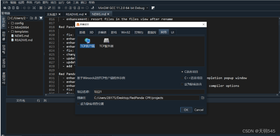
初始化socket dll,通过IP连接服务器对应端口
// 初始化socket dll。
	WORD winsock_version = MAKEWORD(2,2);
	WSADATA wsa_data;
	if (WSAStartup(winsock_version, &wsa_data) != 0) {
		printf("Failed to init socket!\n");
		return 1;
	}

	SOCKET client_socket = socket(AF_INET, SOCK_STREAM, IPPROTO_TCP);
	if (client_socket == INVALID_SOCKET) {
		printf("Failed to create server socket!\n");
		return 2;
	}

	struct sockaddr_in server_addr;
	server_addr.sin_family = AF_INET;
	server_addr.sin_port = htons(PORT);
	server_addr.sin_addr.S_un.S_addr = inet_addr(SERVER_IP);
	if (connect(client_socket, (LPSOCKADDR)&server_addr, sizeof(server_addr)) == SOCKET_ERROR) {
		printf("Failed to connect server: %ld !\n", GetLastError());
		return 3;
	}
.输入指令格式
uint8_t data[length_8];
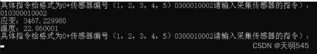
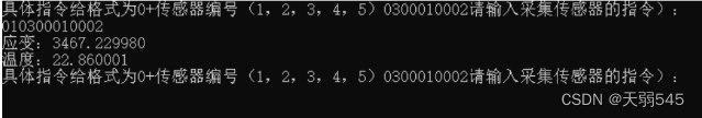
printf("具体指令给格式为0+传感器编号(1,2,3,4,5)0300010002");
printf("请输入采集传感器的指令):\r\n");
scanf("%s",data);
生成将输入指令转化为hex格式并生成crc16校验码
uint16_t crc;
        unsigned char * cmd;
        char crc1[8];
        cmd = fromhex(data);
        crc = CRC_16(cmd);
        uint8_t a = 0xFF;
        for(int i=0;i<6;i++){
            //TODO
            crc1[i] = cmd[i];
        }
        crc1[6] = a & crc;
        crc1[7] = (crc >> 8) & a;
去校验码低位和高位组成2byte的crc16校验位
对应的fromhex函数和crc16校验码生成函数CRC_16会在后面给出
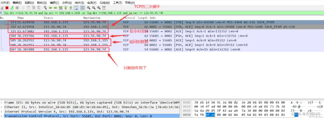
发送,接收数据并使用wireshark对发送数据进行抓包分析
    if (send(client_socket, crc1, 8, 0) < 0) {
            printf("Failed to send data!\n");
            break;
        }

        int ret = recv(client_socket, recv_data, BUFFER_SIZE, 0);
        if (ret < 0) {
            printf("Failed to receive data!\n");
            break;
        }
        recv_data[ret]=0; // correctly ends received string
        char yb[4],wd[4];
        for(int i=0;i<4;i++){
            //TODO
            yb[i] = recv_data[4+i];
            wd[i] = recv_data[8+i];

        }
        float mic = hexToDec(yb)/100.0;
        float strain_temp = hexToDec(wd)/100.0;
        printf("应变:%f\r\n",mic);
        printf("温度:%f\r\n",strain_temp);


//        printf("Receive data from server: \"%x\"\n",recv_data);
        if (strcmp(data,kExitFlag)==0) {
            printf("Exit!\n");
            break;
        }
添加过滤信息(ip.dst ==123.56.90.74 and ip.src == 192.168.1.115) or (ip.dst ==192.168.1.115 and ip.src == 123.56.90.74) 只显示服务器发送回来的包以及发送过去的包
运行结果
二、STM32F103C8基于Modbus协议读取温湿度
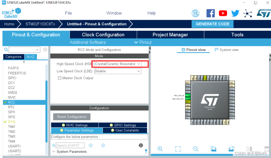
一、使用cubeMX建立项目
选择自己的芯片后,设置外部时钟:
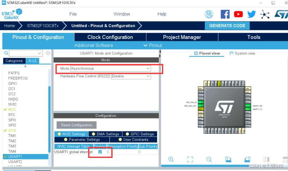
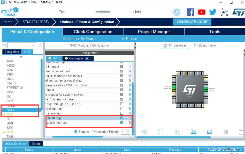
使能一个USART为异步通信,并且加上中断:
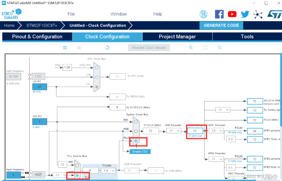
进入时钟设置,将HCLK改为72,然后外部时钟频率为8(不同板子不一样,如果不一样建议上网查一下,如果不和你所用的一致,后面用ModbusPoll会报超时):
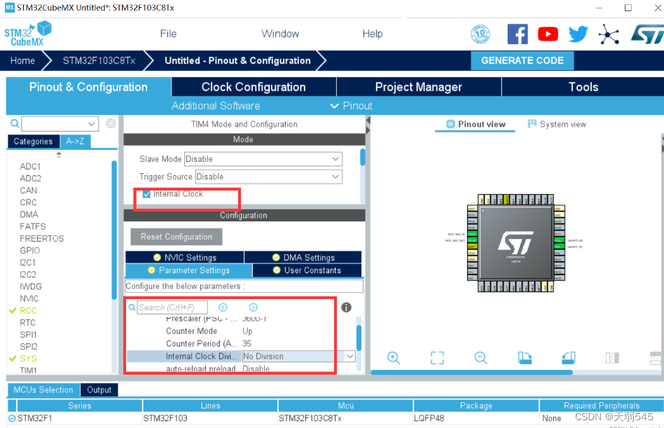
使能定时器4,预分频系数为3600-1,对应的分频频率为20KHz,自动重载值设置为35,得到超时时间1750us,并设置中断:
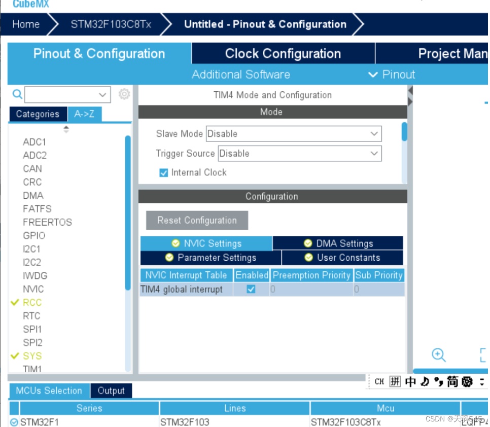
配置中断优先级,定时器中断优先级低于串口中断即可:
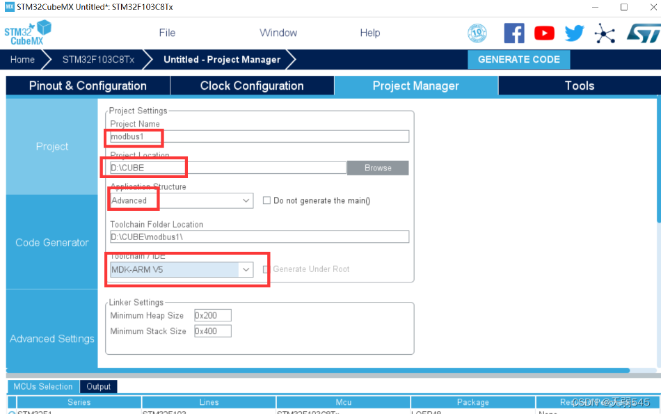
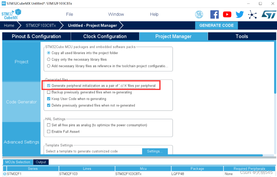
项目管理,然后生成项目就行了:
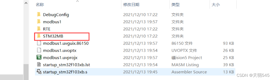
二、移植
在文件夹里打开项目里的MDK-ARM文件,将开始新建的STM32MB文件复制到这里
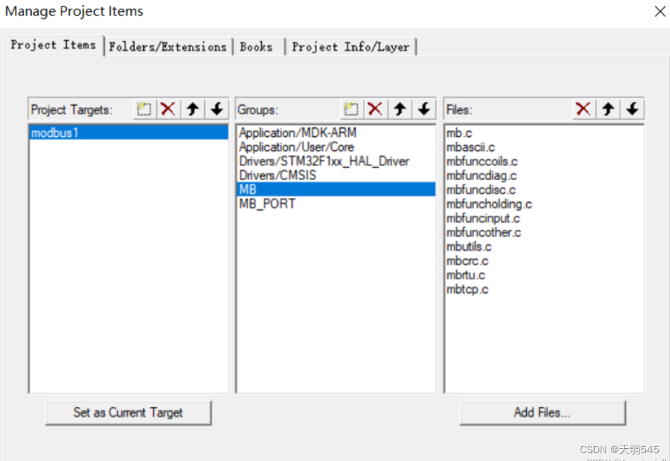
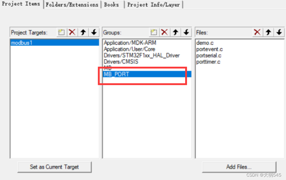
新建名为MB和MB_Port的组,MB内添加STM32MB文件夹下modbus文件夹内所有.c文件,MB_Port内添加STM32MB文件夹下port文件夹内所有.c文件以及根目录的demo.c文件:
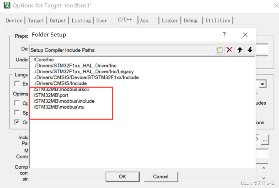
添加头文件路径:
portserial.c文件更改:
vMBPortSerialEnable函数改为
void
vMBPortSerialEnable( BOOL xRxEnable, BOOL xTxEnable )
{
    if (xRxEnable)															//将串口收发中断和modbus联系起来,下面的串口改为自己使能的串口
			{
				__HAL_UART_ENABLE_IT(&huart1,UART_IT_RXNE);	//我用的是串口1,故为&huart1
			}
		else
			{
				__HAL_UART_DISABLE_IT(&huart1,UART_IT_RXNE);
			}
		if (xTxEnable)
			{
				__HAL_UART_ENABLE_IT(&huart1,UART_IT_TXE);
			}
		else
			{
				__HAL_UART_DISABLE_IT(&huart1,UART_IT_TXE);
			}

}
xMBPortSerialInit函数的返回值改为true:
BOOL
xMBPortSerialInit( UCHAR ucPORT, ULONG ulBaudRate, UCHAR ucDataBits, eMBParity eParity )
{
    return TRUE;//改为TURE,串口初始化在usart.c定义,mian函数已完成
}
xMBPortSerialPutByte和xMBPortSerialGetByte更改为:
BOOL
xMBPortSerialPutByte( CHAR ucByte )
{
    /* Put a byte in the UARTs transmit buffer. This function is called
     * by the protocol stack if pxMBFrameCBTransmitterEmpty( ) has been
     * called. */
			if(HAL_UART_Transmit (&huart1 ,(uint8_t *)&ucByte,1,0x01) != HAL_OK )	//添加发送一位代码
			   return FALSE ;
			else
      return TRUE;
}

BOOL
xMBPortSerialGetByte( CHAR * pucByte )
{
    /* Return the byte in the UARTs receive buffer. This function is called
     * by the protocol stack after pxMBFrameCBByteReceived( ) has been called.
     */
    if(HAL_UART_Receive (&huart1 ,(uint8_t *)pucByte,1,0x01) != HAL_OK )//添加接收一位代码
			    return FALSE ;
	   else
       return TRUE;
}
将prvvUARTTxReadyISR和prvvUARTRxISR前面的static删除,记得也在对应声明里删掉:
void prvvUARTTxReadyISR( void )
{
    pxMBFrameCBTransmitterEmpty(  );
}

/* Create an interrupt handler for the receive interrupt for your target
 * processor. This function should then call pxMBFrameCBByteReceived( ). The
 * protocol stack will then call xMBPortSerialGetByte( ) to retrieve the
 * character.
 */
 void prvvUARTRxISR( void )
{
    pxMBFrameCBByteReceived(  );
}
porttimer.c文件:
/*
 * FreeModbus Libary: BARE Port
 * Copyright (C) 2006 Christian Walter <wolti@sil.at>
 *
 * This library is free software; you can redistribute it and/or
 * modify it under the terms of the GNU Lesser General Public
 * License as published by the Free Software Foundation; either
 * version 2.1 of the License, or (at your option) any later version.
 *
 * This library is distributed in the hope that it will be useful,
 * but WITHOUT ANY WARRANTY; without even the implied warranty of
 * MERCHANTABILITY or FITNESS FOR A PARTICULAR PURPOSE.  See the GNU
 * Lesser General Public License for more details.
 *
 * You should have received a copy of the GNU Lesser General Public
 * License along with this library; if not, write to the Free Software
 * Foundation, Inc., 51 Franklin St, Fifth Floor, Boston, MA  02110-1301  USA
 *
 * File: $Id$
 */

/* ----------------------- Platform includes --------------------------------*/
#include "port.h"
#include "stm32f1xx_hal.h"
#include "tim.h"
/* ----------------------- Modbus includes ----------------------------------*/
#include "mb.h"
#include "mbport.h"

/* ----------------------- static functions ---------------------------------*/
void prvvTIMERExpiredISR( void );

/* ----------------------- Start implementation -----------------------------*/
BOOL
xMBPortTimersInit( USHORT usTim1Timerout50us )//定时器初始化直接返回TRUE,已经在mian函数初始化过
{
    return  TRUE;
}


inline void
vMBPortTimersEnable(  )//使能定时器中断,我用的是定时器4,所以为&htim4
{
    /* Enable the timer with the timeout passed to xMBPortTimersInit( ) */
				 /* Enable the timer with the timeout passed to xMBPortTimersInit( ) */
		__HAL_TIM_CLEAR_IT(&htim4,TIM_IT_UPDATE);
		__HAL_TIM_ENABLE_IT(&htim4,TIM_IT_UPDATE);
		__HAL_TIM_SET_COUNTER(&htim4,0);
		__HAL_TIM_ENABLE(&htim4);
}

inline void
vMBPortTimersDisable(  )//取消定时器中断
{
    /* Disable any pending timers. */
	__HAL_TIM_DISABLE(&htim4);
			__HAL_TIM_SET_COUNTER(&htim4,0);
			__HAL_TIM_DISABLE_IT(&htim4,TIM_IT_UPDATE);
			__HAL_TIM_CLEAR_IT(&htim4,TIM_IT_UPDATE);

}

/* Create an ISR which is called whenever the timer has expired. This function
 * must then call pxMBPortCBTimerExpired( ) to notify the protocol stack that
 * the timer has expired.
 */
void prvvTIMERExpiredISR( void )//modbus定时器动作,需要在中断内使用
{
    ( void )pxMBPortCBTimerExpired(  );
}
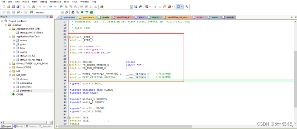
port.h文件:
#ifndef _PORT_H
#define _PORT_H

#include <assert.h>
#include <inttypes.h>
#include "stm32f1xx_hal.h"


#define	INLINE                      inline
#define PR_BEGIN_EXTERN_C           extern "C" {
#define	PR_END_EXTERN_C             }

#define ENTER_CRITICAL_SECTION( )   __set_PRIMASK(1) 	 //关总中断
#define EXIT_CRITICAL_SECTION( )    __set_PRIMASK(0)   //开总中断
stm32f1xx_it.c文件:
/* USER CODE BEGIN PFP */
extern void prvvUARTTxReadyISR(void);
extern void prvvUARTRxISR(void);
extern void prvvTIMERExpiredISR( void );

/* USER CODE END PFP */
更改串口1的中断处理函数:
void USART1_IRQHandler(void)
{
  /* USER CODE BEGIN USART1_IRQn 0 */

  /* USER CODE END USART1_IRQn 0 */
  HAL_UART_IRQHandler(&huart1);
  /* USER CODE BEGIN USART1_IRQn 1 */
if(__HAL_UART_GET_IT_SOURCE(&huart1, UART_IT_RXNE)!= RESET)
		{
			prvvUARTRxISR();//接收中断
		}

	if(__HAL_UART_GET_IT_SOURCE(&huart1, UART_IT_TXE)!= RESET)
		{
			prvvUARTTxReadyISR();//发送中断
		}

  HAL_NVIC_ClearPendingIRQ(USART1_IRQn);
  HAL_UART_IRQHandler(&huart1);
  /* USER CODE END USART1_IRQn 1 */
}
增加定时器中断回调函数,注意增加的位置:
/* USER CODE BEGIN 1 */
void HAL_TIM_PeriodElapsedCallback(TIM_HandleTypeDef *htim)	//定时器中断回调函数,用于连接porttimer.c文件的函数
{
  /* NOTE : This function Should not be modified, when the callback is needed,
            the __HAL_TIM_PeriodElapsedCallback could be implemented in the user file
   */
  	prvvTIMERExpiredISR( );
}

/* USER CODE END 1 */
demo.c文件:
/* ----------------------- Modbus includes ----------------------------------*/
#include "mb.h"
#include "mbport.h"

/* ----------------------- Defines ------------------------------------------*/
#define REG_INPUT_START 0
#define REG_INPUT_NREGS 5

/* ----------------------- Static variables ---------------------------------*/
static USHORT   usRegInputStart = REG_INPUT_START;
//static
uint16_t   usRegInputBuf[REG_INPUT_NREGS];
uint16_t InputBuff[5];

eMBErrorCode
eMBRegInputCB( UCHAR * pucRegBuffer, USHORT usAddress, USHORT usNRegs )
{
    eMBErrorCode    eStatus = MB_ENOERR;
    int             iRegIndex;
		int             i;
		InputBuff[0] = 0x11;
		InputBuff[1] = 0x22;
		InputBuff[2] = 0x33;
		InputBuff[3] = 0x44;

    if( ( usAddress >= REG_INPUT_START )
        && ( usAddress + usNRegs <= REG_INPUT_START + REG_INPUT_NREGS ) )
    {
        iRegIndex = ( int )( usAddress - usRegInputStart );
				for(i=0;i<usNRegs;i++)
				{
					*pucRegBuffer=InputBuff[i+usAddress-1]>>8;
					pucRegBuffer++;
					*pucRegBuffer=InputBuff[i+usAddress-1]&0xff;
					pucRegBuffer++;
				}
    }
    else
    {
        eStatus = MB_ENOREG;
    }

    return eStatus;
}

eMBErrorCode
eMBRegHoldingCB( UCHAR * pucRegBuffer, USHORT usAddress, USHORT usNRegs,
                 eMBRegisterMode eMode )
{
    return MB_ENOREG;
}


eMBErrorCode
eMBRegCoilsCB( UCHAR * pucRegBuffer, USHORT usAddress, USHORT usNCoils,
               eMBRegisterMode eMode )
{
    return MB_ENOREG;
}

eMBErrorCode
eMBRegDiscreteCB( UCHAR * pucRegBuffer, USHORT usAddress, USHORT usNDiscrete )
{
    return MB_ENOREG;
}
main.c:
启动modbus需要在main函数进行初始化、开启侦听操作,所以需要在main.c里添加代码,添加头文件,注意添加的位置:
/* USER CODE BEGIN Includes */
#include "mb.h"
#include "mbport.h"
/* USER CODE END Includes */
mian函数:
int main(void)
{
  /* USER CODE BEGIN 1 */

  /* USER CODE END 1 */

  /* MCU Configuration--------------------------------------------------------*/

  /* Reset of all peripherals, Initializes the Flash interface and the Systick. */
  HAL_Init();

  /* USER CODE BEGIN Init */

  /* USER CODE END Init */

  /* Configure the system clock */
  SystemClock_Config();

  /* USER CODE BEGIN SysInit */

  /* USER CODE END SysInit */

  /* Initialize all configured peripherals */
  MX_GPIO_Init();
  MX_TIM4_Init();
  MX_USART1_UART_Init();
  /* USER CODE BEGIN 2 */
		eMBInit( MB_RTU, 0x01, 1, 115200, MB_PAR_NONE);//初始化modbus,走modbusRTU,从站地址为0x01,端口为1。
	 eMBEnable(  );//使能modbus
  /* USER CODE END 2 */

  /* Infinite loop */
  /* USER CODE BEGIN WHILE */
  while (1)
  {
    /* USER CODE END WHILE */
			( void )eMBPoll(  );//启动modbus侦听
    /* USER CODE BEGIN 3 */
  }
  /* USER CODE END 3 */
}
烧录
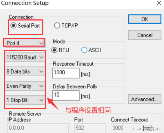
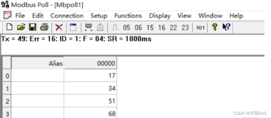
三、测试结果
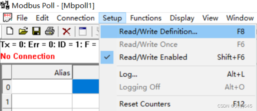
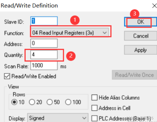
点击connection的connect,进入连接设置,使用的是usb转ttl,用的是com端口,连接的口是com4,所以选择的是port4:
四、实验总结
步骤比较繁琐,需要谨慎


 被折叠的 条评论
为什么被折叠?
被折叠的 条评论
为什么被折叠?
 到【灌水乐园】发言


