


5. 路径层 CDC::BeginPath,BeginPath
如何在Device Context中建立了一个路径层:
1)即调用BeginPath()
2)再调用其他的GDI绘图函数参数一个区域,如Rectangle生成一个矩形区域
3)调用EndPath() 产生闭环的路径层(即一个绘图区域)
pDC->BeginPath();
pDC->Rectangle(200,200,200+csz.cx,200+csz.cy);
//pDC->TextOut(200,200,cstr);//好像路径层上不能输出文本?只能画点,矩形,椭圆等绘图操作?
看来路径层确实只是圈了一块区域,是用点,矩形,椭圆等等图形区域来圈出的路径层(即区域),然后再与客户区进行
图形区域叠加运算
pDC->EndPath();
SelectClipPath(RGN_DIFF);//把路径层的绘图区域与Device Context中的绘图区域进行 OR,XOR,COPY,AND,DIFF运算.
这5个参数会产生新的不同的绘图区,那么就对下面的画横线和竖线的现实产生影响.
总之: 路径区圈好后,还必须与客户区进行5种SelectClipPath()"裁剪"运算,产生新的绘图区域,在新的绘图区域上的绘图就能显示出路径层的特效.
- //------路径层 CDC::BeginPath, EndPath
- CString cstr;
- cstr="VC++ 路径层用矩形圈出的绘图区域";
- pDC->TextOut(100,100,cstr);
- CSize csz;
- csz = pDC->GetTextExtent(cstr);
- pDC->BeginPath();
- pDC->Rectangle(100,100,100+csz.cx,100+csz.cy);//在路径层上绘制一个矩形:就是字符串cstr的所占的区域
- pDC->EndPath(); // 如果不取消则下面画的横竖线就看不见,因为还是在路径层上
- pDC->SelectClipPath(RGN_XOR);//把路径层的绘图与Device Context中的绘图区域进行 OR,XOR,COPY,AND,DIFF运算,产生了新的绘图区
//
CDC::SelectClipPath
BOOL SelectClipPath( int nMode );
Return Value
Nonzero if the function is successful; otherwise 0.
Parameters
nMode
Specifies the way to use the path. The following values are allowed:
- RGN_AND The new clipping region includes the intersection (overlapping areas) of the current clipping region and the current path.
- RGN_COPY The new clipping region is the current path.
- RGN_DIFF The new clipping region includes the areas of the current clipping region, and those of the current path are excluded.
- RGN_OR The new clipping region includes the union (combined areas) of the current clipping region and the current path.
- RGN_XOR The new clipping region includes the union of the current clipping region and the current path, but without the overlapping areas
直接用一个矩形 (100,100,200,200)来圈一个路径层,不用上面的一行字符的区域来圈了.
代码:
- //------路径层 CDC::BeginPath, EndPath
- CString cstr;
- cstr="路径层";
- pDC->TextOut(150,150,cstr); //把cstr输出在(150,150)这个点是将要创建的路径层的中心
- pDC->BeginPath();
- pDC->Rectangle(100,100,200,200);//在路径层上绘制一个矩形:就是字符串cstr的所占的区域
- pDC->EndPath(); // 如果不取消则下面画的横竖线就看不见,因为还是在路径层上
- pDC->SelectClipPath(RGN_OR);//把路径层的绘图与Device Context中的绘图区域进行 OR,XOR,COPY,AND,DIFF运算,产生了新的绘图区
- //下面的横竖线就是在新的绘图区上绘制,
- for(int i=0;i<300;i+=10)
- {
- //画横线
- pDC->MoveTo(0,i);
- pDC->LineTo(300,i);
- //画竖线
- pDC->MoveTo(i,0);
- pDC->LineTo(i,300);
- }
1. 不进行"裁剪" 也就是注释掉 // pDC->SelectClipPath(RGN_OR);

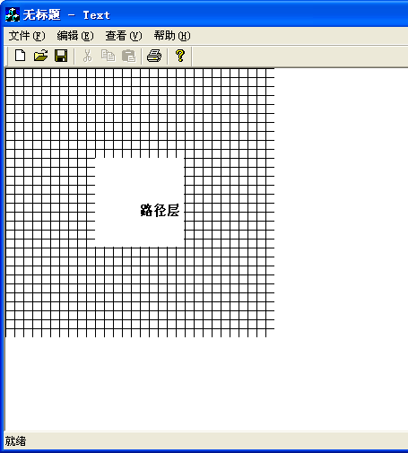
2. pDC->SelectClipPath(RGN_OR): 客户区与路径区的合集

3 pDC->SelectClipPath(RGN_XOR): 客户区与路径区的非交集. 也就是包括了客户区与路径区,但是排除掉他们重叠的部分.本示例中路径区完全位于客户区,所以路径区就是被
排除掉的那个重叠区.

4 pDC->SelectClipPath(RGN_COPY) :只包括当前路径区

5. pDC->SelectClipPath(RGN_AND):原有客户区与路径区的交集
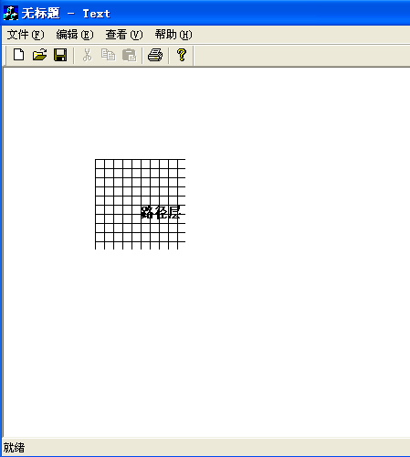
6 pDC->SelectClipPath(RGN_DIFF): 包括原有客户区,不包括路径区
所有源代码:
- // TextView.cpp : implementation of the CTextView class
- //
- #include "stdafx.h"
- #include "Text.h"
- #include "TextDoc.h"
- #include "TextView.h"
- #ifdef _DEBUG
- #define new DEBUG_NEW
- #undef THIS_FILE
- static char THIS_FILE[] = __FILE__;
- #endif
- /
- // CTextView
- IMPLEMENT_DYNCREATE(CTextView, CView)
- BEGIN_MESSAGE_MAP(CTextView, CView)
- //{{AFX_MSG_MAP(CTextView)
- ON_WM_CREATE() //在 Message map tables for Windows messages消息映射表中定义的宏,调用OnCreate函数
- //}}AFX_MSG_MAP
- // Standard printing commands
- ON_COMMAND(ID_FILE_PRINT, CView::OnFilePrint)
- ON_COMMAND(ID_FILE_PRINT_DIRECT, CView::OnFilePrint)
- ON_COMMAND(ID_FILE_PRINT_PREVIEW, CView::OnFilePrintPreview)
- END_MESSAGE_MAP()
- /
- // CTextView construction/destruction
- CTextView::CTextView()
- {
- // TODO: add construction code here
- }
- CTextView::~CTextView()
- {
- }
- BOOL CTextView::PreCreateWindow(CREATESTRUCT& cs)
- {
- // TODO: Modify the Window class or styles here by modifying
- // the CREATESTRUCT cs
- return CView::PreCreateWindow(cs);
- }
- /
- // CTextView drawing
- void CTextView::OnDraw(CDC* pDC) // 这个函数传入了一个device context指针,因为在客户区画图不用在定义一个DC了.
- {
- CTextDoc* pDoc = GetDocument();
- ASSERT_VALID(pDoc);
- // TODO: add draw code for native data here
- //------路径层 CDC::BeginPath, EndPath
- CString cstr;
- cstr="路径层";
- pDC->TextOut(150,150,cstr); //把cstr输出在(150,150)这个点是将要创建的路径层的中心
- pDC->BeginPath();
- pDC->Rectangle(100,100,200,200);//在路径层上绘制一个矩形:就是字符串cstr的所占的区域
- pDC->EndPath(); // 如果不取消则下面画的横竖线就看不见,因为还是在路径层上
- pDC->SelectClipPath(RGN_DIFF);//把路径层的绘图与Device Context中的绘图区域进行 OR,XOR,COPY,AND,DIFF运算,产生了新的绘图区
- //下面的横竖线就是在新的绘图区上绘制,
- for(int i=0;i<300;i+=10)
- {
- //画横线
- pDC->MoveTo(0,i);
- pDC->LineTo(300,i);
- //画竖线
- pDC->MoveTo(i,0);
- pDC->LineTo(i,300);
- }
- }
- /
- // CTextView printing
- BOOL CTextView::OnPreparePrinting(CPrintInfo* pInfo)
- {
- // default preparation
- return DoPreparePrinting(pInfo);
- }
- void CTextView::OnBeginPrinting(CDC* /*pDC*/, CPrintInfo* /*pInfo*/)
- {
- // TODO: add extra initialization before printing
- }
- void CTextView::OnEndPrinting(CDC* /*pDC*/, CPrintInfo* /*pInfo*/)
- {
- // TODO: add cleanup after printing
- }
- /
- // CTextView diagnostics
- #ifdef _DEBUG
- void CTextView::AssertValid() const
- {
- CView::AssertValid();
- }
- void CTextView::Dump(CDumpContext& dc) const
- {
- CView::Dump(dc);
- }
- CTextDoc* CTextView::GetDocument() // non-debug version is inline
- {
- ASSERT(m_pDocument->IsKindOf(RUNTIME_CLASS(CTextDoc)));
- return (CTextDoc*)m_pDocument;
- }
- #endif //_DEBUG
- /
- // CTextView message handlers
- int CTextView::OnCreate(LPCREATESTRUCT lpCreateStruct)
- {
- if (CView::OnCreate(lpCreateStruct) == -1)
- return -1;
- // TODO: Add your specialized creation code here
- // GetSystemMetrics
- //------创建文本插入符
- /*
- CClientDC dc(this);
- TEXTMETRIC tm;
- dc.GetTextMetrics(&tm);
- CreateSolidCaret(tm.tmAveCharWidth/8,tm.tmHeight);
- ShowCaret();
- */
- //------创建图形插入符
- /*
- 1. 创建一个位图对象CBitmap bitmap,且应作为全局的成员存在,因此把这个对象作为CTextView类的一个私有成员.
- 2. CreateCare()函数来创建一个插入符
- 3. 发现运行后闪烁的位图背景色和前景色均不是我设计的那个颜色,奇怪了...
- */
- // CBitmap bitmap; 放在这里没有用,OnCreate消息处理完函数返回(return 0)后,这个临时bitmap资源类对象发生了析构,内存中没有了.
- bitmap.LoadBitmap(IDB_BITMAP1);
- CClientDC dc(this);
- // CreateCaret(&bitmap);
- // ShowCaret();
- //---
- return 0;
- }


 1万+
1万+

 被折叠的 条评论
为什么被折叠?
被折叠的 条评论
为什么被折叠?
 到【灌水乐园】发言


