电源管理始终是手机等移动设备最重要的一个功能,尤其对于Android这种智能手机或者说手机电脑化的设备,电源管理更显得十分重要。Linux一直在传统的PC和服务器市场上有很好的应用,也有了比较好的电源管理框架,但是对于智能手机等嵌入式设备来说,Linux标准的电源管理就显得不是很适用了,有许多需要改进的地方。Android在这方面做了一些比较好的尝试,在这里我们将详细的介绍Android系统的电源管理系统,我们也不会仅仅局限在Android上,也会探讨一些比较好的电源管理技术,也会针对比较流行的OMAP平台探讨一些跟硬件相关的电源管理技术。
包括:Android suspend blocker(wake_lock),Android earylysuspend,Linux suspend framework, Linix Idle framework, LinuxCPUFreq framework。其中Wake Lock和earylysuspend是Android电源管理的两个核心功能,由于这两个驱动都是基于Linux系统标准的Suspend框架,因此我们首先来看看Linux系统Suspend框架,然后再来具体分析WakeLock和early Suspend。
2.2.1 Linux Suspend/Resume Framework
Suspend/Resume是Linux系统电源管理的一个重要功能,Suspend可以在系统不使用的情况下进入低功耗活休眠状态下从而节省系统电源。Linux系统的Suspend有四种状态,对于不同的体系结构或者电源管理接口来说,状态的含义不一定完全相同,但是不会有太大的差别。下面的是ACPI电源接口的含义及其对应的SleepState。
- On(on) S0 - Working
- Standby (standby) S1 - CPU andRAMare powered but not executed
- Suspend to RAM(mem) S3 -RAM is powered and the running content is saved to RAM
- Suspend to Disk,Hibernation(disk) S4 -
Linux系统的电源管理Suspend框架跟Linux系统的驱动模型(Linux DriverModel)是相关的,也是基于Linux的驱动模型来实现的,下面的图描述了Linux系统电源管理的Suspend系统框架,Linux的Suspend系统分为两部分,一部分是平台无关的核心层,另一个是平台相关的平台层。操作接口都在平台无关的核心层里了,平台相关部分
根据Linux系统驱动模型,Device结构描述了一个设备,device_driver是设备的驱动,而class、type和bus分别描述了设备所属的类别、类型和总线。而设备的电源管理也根据此模型分为class级的、type级的、bus级的和驱动级的。如果一个设备的class或者bus确切的知道如何管理一个设备的电源的时候,驱动级别的suspend/resume就可以为空了。这极大的提高了电源管理的高效性和灵活性。
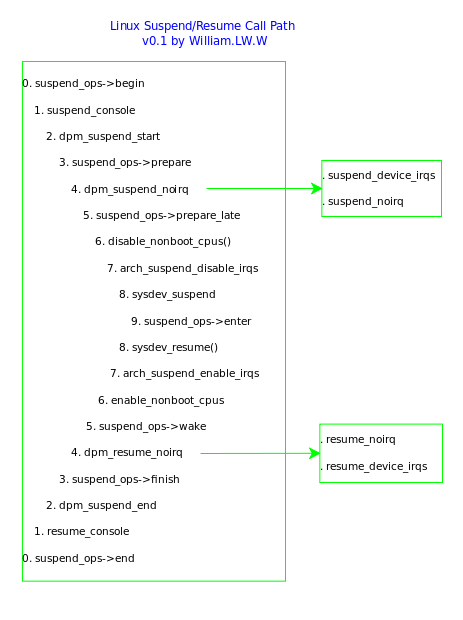
Linxux系统的suspend核心代码位于kernel/power目录下,主要的文件是main.c 和suspend.c。平台相关的代码一般位于平台(arch)的电源管理模块里,比如ARMOMAP34xx的电源管理(arch/arm/mach-omap2/pm-34xx.c)。这里我们将按照驱动程序的接口和调用过程来描述Linux系统是任何实现suspend电源管理功能的。下面的图描述了Linux系统的Suspend函数调用路径,可以看到Suspend和Resume的函数都是相对应的。
- 用户空间接口
首先我们来看一下suspend的用户空间接口,这是一个/sys文件系统接口,接口文件是/sys/power/state。这是我们在用户空间操作Suspend的唯一的一个接口。当我们向这个文件写入想要进入的有效的suspend状态的时候,系统就会调用Suspend函数进入到一个有效的suspend状态。比如我们向这个文件写入mem就会使系统进入Suspendto RAM状态,如下的命令:
echo mem > /sys/power/state
驱动在收到这个数据时就调用state_store函数来处理输入的状态,默认的状态是PM_SUSPEND_STANDBY,函数首先检查是否要进入Hibernation状态,如果是就调用hibernate()函数进入Hibernation状态,如果不是就找到要进入的状态,并调用suspend的enter_state函数进入suspend状态。我们看到在驱动的实现上把Suspend和Hibernation区分开了。因此Linux的PMSuspendState就有两个,standby和mem。注意这里没有on,因此你不能通过发送on命来到/sys/power/state或其他内核接口函数来唤醒系统,因为这是针对服务器/PC的,只能通过按键的方式(大多数的PC/笔记本都提供了Suspend键,也可能就是Power键)。
suspend_state_t state = PM_SUSPEND_STANDBY;
if (len == 4 && !strncmp(buf,"disk", len)) {
error = hibernate();
}
if (state < PM_SUSPEND_MAX&& *s)
error =enter_state(state);
enter_state是suspend.c里定义的接口函数,用来使系统进入指定的suspend状态。好了,剩下的事情就交给Suspend系统来处理了。
- 内核驱动接口及实现
Suspend接口函数
内核suspend核心系统定义了几个非局部的函数作为Suspend的接口函数(linux/suspend.h),前面的enter_state就是其中的一个,他们是:
int pm_suspend(suspend_state_t state);
void suspend_set_ops(struct platform_suspend_ops *ops);
int suspend_valid_only_mem(suspend_state_t state);
bool valid_state(suspend_state_t state);
但是这里并不是所有函数都EXPORT出来供其他模块函数使用。其实EXPORT出来的函数只有一个,就是pm_suspend。因此pm_suspend是唯一的一个外部可见的Suspend系统接口函数。pm_suspend函数接口很简单,就是enter_state函数的简单封装,它首先判断状态是否有效,如果有效就直接调用enter_state函数进入指定的状态。
int pm_suspend(suspend_state_t state)
{
if (state > PM_SUSPEND_ON&& state <=PM_SUSPEND_MAX)
returnenter_state(state);
return -EINVAL;
}
suspend_set_ops函数是提供给平台底层用来设置平台自己的suspend函数的。
suspend_valid_only_mem是一个通用的验证函数,用来验证是否仅支持PM_SUSPEND_MEM(mem)状态,提供这个函数是因为大多的平台也仅仅是支持PM_SUSPEND_MEM状态,因此suspend系统提供了这样一个函数,这样各个平台就可以共享而不用单独实现自己的验证函数了。
valid_state是一个suspend系统的验证函数,它会调用平台底层valid函数来验证当前的平台是否支持某一个状态。
System SuspendPath(路径)
前面我们提到了Suspend/Resume的调用路径,也称之为Suspend Path。这里我们详细的描述系统suspendpath及其功能。
Enter_suspend
首先是enter_suspend函数,这个函数处理进入和退出Suspend状态时的一些常规处理,其过程是:
第一,同步文件系统以保证所有数据都写到了存储设备上而不会因为suspend而丢失数据
sys_sync();
第二,调用suspend_prepare准备进入suspend状态,完成后,系统suspend状态变为PM_SUSPEND_PREPARE。这个函数主要完成几件事情:1)切换Console为SUSPEND_CONSOLE。2)通知pm_chain系统进入PM_SUSPEND_PREPARE状态(通过kernelnotifier机制)。3)关闭usermodehelper函数以阻止新的helper函数运行。4)冻结所有可冻结的任务(包括用户空间程序和部分内核空间线程)
pm_prepare_console();
pm_notifier_call_chain(PM_SUSPEND_PREPARE);
usermodehelper_disable();
suspend_freeze_processes();
第三,调用suspend_devices_and_enter(state);进入指定的suspend状态。
第四,系统已经从suspend里唤醒,调用suspend_finish()完成suspend操作。这个函数的功能与suspend_prepare相反的,目的是恢复suspend_prepare为进入suspend而进行的一些处理,就不详细描述了。
suspend_thaw_processes();
usermodehelper_enable();
pm_notifier_call_chain(PM_POST_SUSPEND);
pm_restore_console();
suspend_devices_and_enter
Overview
The above picture shows the overall architecture design of Android power management module. Android implements a very simple power management mechanism. Currently it only supports set screen on/off, screen backlight on/off, keyboard backlight on/off, button backlight on/off and adjust screen brightness. It does not support Sleep or Standby mode to fully use CPU’s capability.
The power management module has three channels to receive input: RPC call, Batter state change event and Power Setting change event. It communicated with other modules through either broadcasting intent or directly API call. The module also provide reboot and shutdown service. When battery is lower than thredshold, it will automatically shutdown the device.
The module will automatically set screen dim and off according to whether any user activity happens or not. The full state machine is shown as follows:
Detail
PowerManagerService.java is the core service. It calls Power.java to do the real work.
PowerManager.java is the proxy to RPC call PowerManagerService.java.
Power.java communicates with the low level through JNI.
android_os_Power.cpp is the JNI native implementation for Power.java. It calls Power.c to do the real work.
Power.c controls the power device driver through read/write the following sys files.
"/sys/android_power/acquire_partial_wake_lock",
"/sys/android_power/acquire_full_wake_lock",
"/sys/android_power/release_wake_lock",
"/sys/android_power/request_state"
"/sys/android_power/auto_off_timeout",
"/sys/class/leds/lcd-backlight/brightness",
"/sys/class/leds/button-backlight/brightness",
"/sys/class/leds/keyboard-backlight/brightness"
BatteryService.java registers itself as a UEvent observer for the path “/sys/class/power_supply”. If anything is changed in this path, it gets current state through JNI and then broadcasts ACTION_BATTERY_CHANGED intent.
com_android_server_BatteryService.cpp is the JNI native implementation for BatteryService.java. It gets current battery state through reading from the following files:
"/sys/class/power_supply/ac/online"
"/sys/class/power_supply/usb/online"
"/sys/class/power_supply/battery/status"
"/sys/class/power_supply/battery/health"
"/sys/class/power_supply/battery/present"
"/sys/class/power_supply/battery/capacity"
"/sys/class/power_supply/battery/batt_vol"
"/sys/class/power_supply/battery/batt_temp"
"/sys/class/power_supply/battery/technology"
How to use
To call power module in app, the following is the sample code:
PowerManager pm = (PowerManager)mContext.getSystemService(Context.POWER_SERVICE);
PowerManager.WakeLock wl = pm.newWakeLock(
PowerManager.SCREEN_DIM_WAKE_LOCK
| PowerManager.ON_AFTER_RELEASE,
TAG);
wl.acquire();
// ...
wl.release();
加上内核部分的代码和android电源管理部分的源码,理一理,大概的框架应该理解了。。。
LINUX内核中的xx_initcall初始化标号
田海立@CSDN 2011-07-02
LINUX内核中有很多的初始化指示标志postcore_initcall(), arch_initcall(), subsys_initcall(), device_initcall(), etc. 这些起什么作用呢?查阅源代码(android goldfish-2.6.29)并搜索网上相关文章,对此做一总结。
- 初始化标号
先看这些宏的定义(定义在文件include/linux/init.h中)
- #define pure_initcall(fn) __define_initcall("0",fn,0)
- #define core_initcall(fn) __define_initcall("1",fn,1)
- #define core_initcall_sync(fn) __define_initcall("1s",fn,1s)
- #define postcore_initcall(fn) __define_initcall("2",fn,2)
- #define postcore_initcall_sync(fn) __define_initcall("2s",fn,2s)
- #define arch_initcall(fn) __define_initcall("3",fn,3)
- #define arch_initcall_sync(fn) __define_initcall("3s",fn,3s)
- #define subsys_initcall(fn) __define_initcall("4",fn,4)
- #define subsys_initcall_sync(fn) __define_initcall("4s",fn,4s)
- #define fs_initcall(fn) __define_initcall("5",fn,5)
- #define fs_initcall_sync(fn) __define_initcall("5s",fn,5s)
- #define rootfs_initcall(fn) __define_initcall("rootfs",fn,rootfs)
- #define device_initcall(fn) __define_initcall("6",fn,6)
- #define device_initcall_sync(fn) __define_initcall("6s",fn,6s)
- #define late_initcall(fn) __define_initcall("7",fn,7)
- #define late_initcall_sync(fn) __define_initcall("7s",fn,7s)
- __define_initcall
这些宏都用到了__define_initcall(),再看看它的定义(同样定义在文件include/linux/init.h中)
- #define __define_initcall(level,fn,id) \
- static initcall_t __initcall_##fn##id __used \
- __attribute__((__section__(".initcall" level ".init"))) = fn
这其中initcall_t是函数指针,原型如下,
- typedef int (*initcall_t)(void);
而属性 __attribute__((__section__())) 则表示把对象放在一个这个由括号中的名称所指代的section中。
所以__define_initcall的含义是:
1) 声明一个名称为__initcall_##fn的函数指针;
2) 将这个函数指针初始化为fn;
3) 编译的时候需要把这个函数指针变量放置到名称为 ".initcall" level ".init"的section中。
3. 放置.initcall.init SECTION
明确了__define_initcall的含义,就知道了是分别将这些初始化标号修饰的函数指针放到各自的section中的。
SECTION“.initcall”level”.init”被放入INITCALLS(include/asm-generic/vmlinux.lds.h)
- #define INITCALLS \
- *(.initcallearly.init) \
- VMLINUX_SYMBOL(__early_initcall_end) = .; \
- *(.initcall0.init) \
- *(.initcall0s.init) \
- *(.initcall1.init) \
- *(.initcall1s.init) \
- *(.initcall2.init) \
- *(.initcall2s.init) \
- *(.initcall3.init) \
- *(.initcall3s.init) \
- *(.initcall4.init) \
- *(.initcall4s.init) \
- *(.initcall5.init) \
- *(.initcall5s.init) \
- *(.initcallrootfs.init) \
- *(.initcall6.init) \
- *(.initcall6s.init) \
- *(.initcall7.init) \
- *(.initcall7s.init)
__initcall_start和__initcall_end以及INITCALLS中定义的SECTION都是在arch/xxx/kernel/vmlinux.lds.S中放在.init段的。
- SECTIONS
- {
- .init : {
- __initcall_start = .;
- INITCALLS
- __initcall_end = .;
- }
- }
4. 初始化.initcallxx.init里的函数
而这些SECTION里的函数在初始化时被顺序执行(init内核线程->do_basic_setup()[main.c#778]->do_initcalls())。
程序(init/main.c文件do_initcalls()函数)如下,do_initcalls()把.initcallXX.init中的函数按顺序都执行一遍。
- for (call = __early_initcall_end; call < __initcall_end; call++)
- do_one_initcall(*call);


 6205
6205

 被折叠的 条评论
为什么被折叠?


