


1. Requirements
To generate a PWM output, we need to create a train of pulses with constant period and variable duty cycle.
The duty cycle, being the modulation is the pulse width.
Typically, a timer is used to maintain both the period and duty cycle
by toggling an output based on compare matches between the timer and timer registers.
The timer is reset at the end of the pulse’s period in preparation for generating the next pulse.
In this case, the number of PWM will be limited by the number of timers that can operate in PWM mode.
This application note illustrates another method to generate the PWM outputs,
using DMA transfers to create one or two PWM signals.
This can be an advantage when a particular timer (a ‘precious resource’)
with a certain function is needed for other purposes in a design.
Instead, a simpler timer can be used.
2. DMAC Operation
The operation of DMAC on an M16C/6x device is as follows:
- DMAC is initialized with a source address, a destination address, and a number for the amount of data to be transferred.
- The DMA ‘waits’ for a request signal which can be a software or hardware trigger signal.
- After a request signal is received, one byte or one word of data is transferred from the source address to the destination address.
- Depended on the DMA settings, either the source or destination address is incremented, or both addresses stay fixed.
- After a predefined number of data is transferred, the transfer can be repeated at the beginning or stopped.
A variable PWM signal will be created since we can change the source data as we please, and thus vary the duty cycle (pulse width).
We can also change the destination address.
The train of data can be output as an external signal of the MCU if we set the destination address to a specific output port.
3. How the PWM Signal is Created
We need to continuously maintain the pulse’s period and duty cycle.
To have the DMAC maintain the period we use a timer as the DMA request factor.
In the sample application we set up a timer to cause an underflow and then request a DMA transfer.
We can fine tune the signal at the destination output pin to have any level (high or low) at any specific time in one period.
In the following reasoning, a timer period is quantified as the time interval between each timer underflow.
This is Ttimer = PWM period / PWM resolution
To achieve a certain PWM resolution, say N (e.g. 255), we must transfer data N (255) times within one PWM period.
We will operate the DMAC in repeat mode to generate a continuous train of PWM signal.
In this mode, the whole set of data at the source address will be transferred again and again after the completion of the previous one.
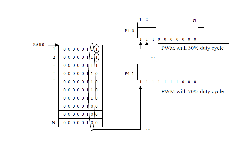
Figure 1. PWM data is through some means apart from the DMA written to the data source buffer, pointed to by SARi.
This data is periodically transferred by the DMAC so that the signals at P4 behave the same way as PWM outputs with pre-defined duty cycle.
An array of data is shown which generate a PWM signal with 30% and 70% duty cycle at pin P4_0 and P4_1.
Up to 8 separate PWM signals can easily be generated in this example, with the same amount of MCU peripherals.
As shown in Figure 1, N data is transferred by N timer interrupts, and then the process is repeated.
N is the value in the TCRi register (Transfer Counter register) and is in fact the PWM resolution.
Data is transferred from the source address (in the SAR register) to the destination address (in the DAR register), which maps to P4.


 被折叠的 条评论
为什么被折叠?
被折叠的 条评论
为什么被折叠?
 到【灌水乐园】发言


