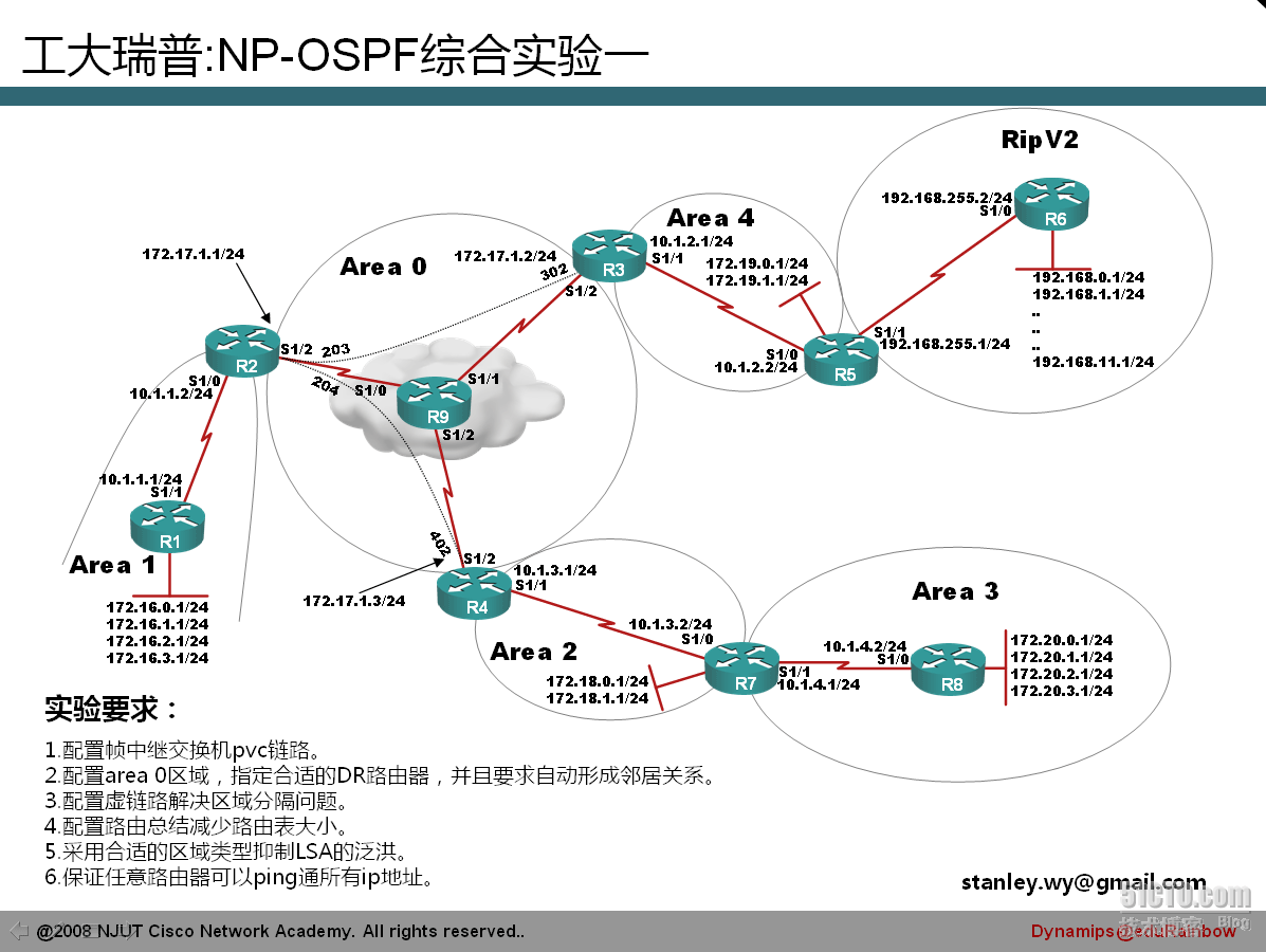
今天完成一个OSPF的综合实验,利用所学知识实战一下:
这里借用以下工大瑞普的OSPF综合实验拓扑图,感谢工大瑞普的分享。

废话不多说,实验开始(每个路由器的接口的IP地址配置省略)
<?xml:namespace prefix = o ns = "urn:schemas-microsoft-com:office:office" />
1.
配置帧中继交换机PVC链路
将图中R9模拟配置成帧中继交换机
首先,应该在全局配置模式下输入
frame-relay switching开启帧中继交换功能
S1/0、S1/1、S1/2配置如下:
interface Serial1/0
no ip address
encapsulation frame-relay
//
接口封装帧中继
shutdown
serial restart-delay 0
clock rate 64000
//
配置时钟,用于同步数据传输的速率
frame-relay lmi-type cisco
//
配置帧中继
LMI
(本地管理接口)封装类型
frame-relay intf-type dce
//
配置帧中继接口类型
frame-relay route 203 interface Serial1/1 302
frame-relay route 204 interface Serial1/2 402
//
配置
DLCI
的路由,在这个配置中意思是从
DLCI
为
204
的数据从
s1/2
口转发出去,并且从
402 DLCI
到达目的地。这条
PVC
由
DLCI 204
和
402
来标识
!
interface Serial1/1
no ip address
encapsulation frame-relay
shutdown
serial restart-delay 0
clock rate 64000
frame-relay lmi-type cisco
frame-relay intf-type dce
frame-relay route 302 interface Serial1/0 203
!
interface Serial1/2
no ip address
encapsulation frame-relay
shutdown
serial restart-delay 0
clock rate 64000
frame-relay lmi-type cisco
frame-relay intf-type dce
frame-relay route 402 interface Serial1/0 204
OK,这样就把R9模拟成帧中继交换机,实验继续
2.配置area 0 区域,指定合适的DR路由器,并且要求自动形成邻居关系。
这里我将帧中继网路类型配置成point to multipoint类型,因此不选举DR/BDR
R2:
interface Serial1/2
ip address 172.17.1.1 255.255.255.0
encapsulation frame-relay
ip ospf network point-to-multipoint
serial restart-delay 0
frame-relay map ip 172.17.1.2 203 broadcast
frame-relay map ip 172.17.1.3 204 broadcast
no frame-relay inverse-arp
!
router ospf 1
log-adjacency-changes
network <?xml:namespace prefix = st1 ns = "urn:schemas-microsoft-com:office:smarttags" />10.1.1.0 0.0.0.255 area 1
network 172.17.1.0 0.0.0.255 area 0
R3:
interface Serial1/2
ip address 172.17.1.2 255.255.255.0
encapsulation frame-relay
ip ospf network point-to-multipoint
serial restart-delay 0
frame-relay map ip 172.17.1.1 302 broadcast
no frame-relay inverse-arp
!
router ospf 1
log-adjacency-changes
network 10.1.2.0 0.0.0.255 area 4
network 172.17.1.0 0.0.0.255 area 0
R4:
interface Serial1/2
ip address 172.17.1.3 255.255.255.0
encapsulation frame-relay
ip ospf network point-to-multipoint
serial restart-delay 0
frame-relay map ip 172.17.1.1 402 broadcast
no frame-relay inverse-arp
!
router ospf 1
log-adjacency-changes
network 10.1.3.0 0.0.0.255 area 2
network 172.17.1.0 0.0.0.255 area 0
我们来看下结果:
r2#sh ip os nei
Neighbor ID Pri State Dead Time Address Interface
172.17.1.3 0 FULL/ - 00:01:47 172.17.1.3 Serial1/2
172.17.1.2 0 FULL/ - 00:01:31 172.17.1.2 Serial1/2
172.16.3.1 1 FULL/ - 00:00:34 10.1.1.1 Serial1/0
实验成功
3.配置虚链路解决区域分割问题
先来看看R4路由器上的路由条目
r4#sh ip rou
172.17.0.0/16 is variably subnetted, 3 subnets, 2 masks
C 172.17.1.0/24 is directly connected, Serial1/2
O 172.17.1.1/32 [110/64] via 172.17.1.1, 00:51:01, Serial1/2
O 172.17.1.2/32 [110/128] via 172.17.1.1, 00:51:01, Serial1/2
172.16.0.0/32 is subnetted, 4 subnets
O IA 172.16.1.1 [110/129] via 172.17.1.1, 00:49:06, Serial1/2
O IA 172.16.0.1 [110/129] via 172.17.1.1, 00:49:06, Serial1/2
O IA 172.16.3.1 [110/129] via 172.17.1.1, 00:49:06, Serial1/2
O IA 172.16.2.1 [110/129] via 172.17.1.1, 00:49:06, Serial1/2
172.19.0.0/32 is subnetted, 2 subnets
O IA 172.19.0.1 [110/193] via 172.17.1.1, 00:49:06, Serial1/2
O IA 172.19.1.1 [110/193] via 172.17.1.1, 00:49:06, Serial1/2
172.18.0.0/32 is subnetted, 2 subnets
O 172.18.1.1 [110/65] via 10.1.3.2, 00:49:06, Serial1/1
O 172.18.0.1 [110/65] via 10.1.3.2, 00:49:06, Serial1/1
10.0.0.0/24 is subnetted, 3 subnets
C 10.1.3.0 is directly connected, Serial1/1
O IA 10.1.2.0 [110/192] via 172.17.1.1, 00:49:06, Serial1/2
O IA 10.1.1.0 [110/128] via 172.17.1.1, 00:49:06, Serial1/2
可以看出R4路由表没有到达区域3的路由信息,造成这种情况的由于区域3没有和主干区域0相连,我们知道OSPF采用层次设计时,非主干区域都必须和主干区域相连,当非主干区域没有和主干区域相连时,OSPF提供了一种解决方法,那就是配置Virtual-link。
Virtual-link配置命令为在路由配置命令下输入
area area-di virtual-link neighbor-id
r4(config)#router os 1
r4(config-router)#area 2 virtual-link 172.18.1.1
r7(config)#router os 1
r7(config-router)#area 2 virtual-link 172.17.1.3
查看下结果:
r4#sh ip ospf virtual-links
Virtual Link OSPF_VL1 to router 172.18.1.1 is up
Run as demand circuit
DoNotAge LSA allowed.
Transit area 2, via interface Serial1/1, Cost of using 64
Transmit Delay is 1 sec, State POINT_TO_POINT,
Timer intervals configured, Hello 10, Dead 40, Wait 40, Retransmit 5
Hello due in 00:00:01
Adjacency State FULL (Hello suppressed)
Index 2/3, retransmission queue length 0, number of retransmission 1
First 0x0(0)/0x0(0) Next 0x0(0)/0x0(0)
Last retransmission scan length is 1, maximum is 1
Last retransmission scan time is 0 msec, maximum is 0 msec
r4#sh ip rou
172.17.0.0/16 is variably subnetted, 3 subnets, 2 masks
C 172.17.1.0/24 is directly connected, Serial1/2
O 172.17.1.1/32 [110/64] via 172.17.1.1, 00:03:39, Serial1/2
O 172.17.1.2/32 [110/128] via 172.17.1.1, 00:03:39, Serial1/2
172.16.0.0/32 is subnetted, 4 subnets
O IA 172.16.1.1 [110/129] via 172.17.1.1, 00:03:39, Serial1/2
O IA 172.16.0.1 [110/129] via 172.17.1.1, 00:03:39, Serial1/2
O IA 172.16.3.1 [110/129] via 172.17.1.1, 00:03:39, Serial1/2
O IA 172.16.2.1 [110/129] via 172.17.1.1, 00:03:39, Serial1/2
172.19.0.0/32 is subnetted, 2 subnets
O IA 172.19.0.1 [110/193] via 172.17.1.1, 00:03:39, Serial1/2
O IA 172.19.1.1 [110/193] via 172.17.1.1, 00:03:39, Serial1/2
172.18.0.0/32 is subnetted, 2 subnets
O 172.18.1.1 [110/65] via 10.1.3.2, 00:03:50, Serial1/1
O 172.18.0.1 [110/65] via 10.1.3.2, 00:03:50, Serial1/1
172.20.0.0/32 is subnetted, 4 subnets
O IA 172.20.1.1 [110/129] via 10.1.3.2, 00:03:40, Serial1/1
O IA 172.20.0.1 [110/129] via 10.1.3.2, 00:03:40, Serial1/1
O IA 172.20.3.1 [110/129] via 10.1.3.2, 00:03:40, Serial1/1
O IA 172.20.2.1 [110/129] via 10.1.3.2, 00:03:40, Serial1/1
10.0.0.0/24 is subnetted, 4 subnets
C 10.1.3.0 is directly connected, Serial1/1
O IA 10.1.2.0 [110/192] via 172.17.1.1, 00:03:40, Serial1/2
O IA 10.1.1.0 [110/128] via 172.17.1.1, 00:03:40, Serial1/2
O IA 10.1.4.0 [110/128] via 10.1.3.2, 00:03:40, Serial1/1
Ok,实验成功。
转载于:https://blog.51cto.com/lovelife/180214


 360
360


 被折叠的 条评论
为什么被折叠?


