一、实验名称
利用三层交换机实现VLAN间路由
二、实验内容
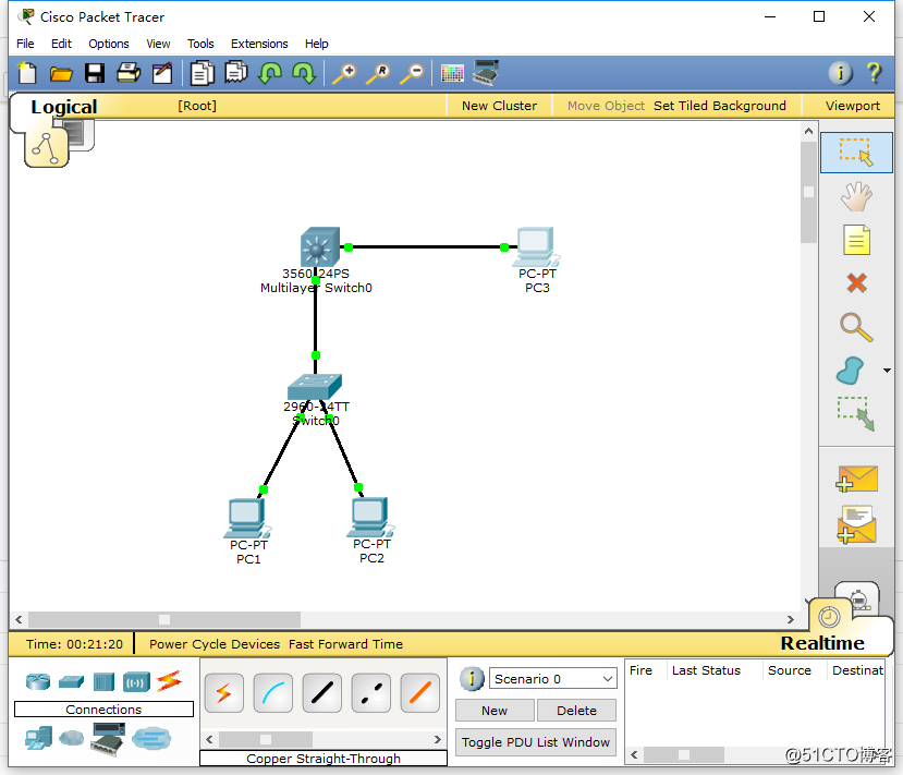
1.新建 packet tracer 拓扑图
2.在二层交换机上配置 VLAN2、 VLAN3,分别将端口 2、端口 3 划分给 VLAN2、
VLAN3。
3.将二层交换机与三层交换机相连的端口 fa 0/1 都定义为 tag Vlan 模式。
4.在三层交换机上配置 VLAN2、 VLAN3,此时验证二层交换机 VLAN2、 VLAN3
下的主机之间不能相互通信。
5.设置三层交换机 VLAN 间的通信,创建 VLAN2,VLAN3 的虚接口,并配置
虚接口 VLAN2、 VLAN3 的 IP 地址。
6.查看三层交换机路由表。
7.将二层交换机 VLAN2、 VLAN3 下的主机默认网关分别设置为相应虚拟接口
的 IP 地址。
8.验证二层交换机 VLAN2,VALN3 下的主机之间可以相互通信。
三、实验过程
1.将Switch_2960 1 台、 Switch_3560 1 台、PC 3 台用直连线互联

2.配置各PC的IP地址、网关
PC1
IP: 192.168.1.2
Submark: 255.255.255.0
Gateway: 192.168.1.1
PC2
IP: 192.168.2.2
Submark: 255.255.255.0
Gateway: 192.168.2.1
PC3
IP: 192.168.1.3
Submark: 255.255.255.0
Gateway: 192.168.1.1
3.配置二层交换机S1
en
conf t
vlan 2
exit
vlan 3
exit
int fa 0/2
switchport access vlan 2
int fa 0/3
switchport access vlan 3
int fa 0/1
switchport mode trunk
exit
show vlan
S3560


4.配置三层交换机
en
conf t
ip routing
vlan 2
exit
vlan 3
exit
int fa 0/1
switchport trunk encapsulation dot1q
switchport mode trunk
exit
int fa 0/2
switchport access vlan 2
exit
interface vlan 2
ip address 192.168.1.1 255.255.255.0
no shutdown
exit
interface vlan 3
ip address 192.168.2.1 255.255.255.0
no shutdown
exit
show ip route
show vlan


四、实验结果
PC3 Ping PC1
Ping 192.168.1.2
PC3 Ping PC2
Ping 192.168.1.3

转载于:https://blog.51cto.com/13396153/2073064


 1万+
1万+


 被折叠的 条评论
为什么被折叠?


