SG-1000
Thank you for your purchase of the pfSense SG-1000 System This hardware platform provides a powerful, reliable, cost-effective solution.
Quick Start Guide
The SG-1000 Quick Start Guide covers the first time connection procedures and will provide you with the information you need to get your appliance up and running.
Premium Documentation
Included with the purchase of an eligible appliance is access to The pfSense Book (700+ pages of premium online documentation and guides). Make sure you have activated your bundled support to gain access.
Frequently Asked Questions
For answers to basic questions about the SG-1000 platform, consult the SG-1000 FAQ.
SG-1000 Quick Start Guide
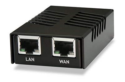
This Quick Start Guide covers first time connection procedures for a new appliance.
Table of Contents
I/O Ports

Ports are assigned as pictured.
Front
LAN (cpsw1)
WAN (cpsw0)
Back
Console (Micro-USB)
USB OTG
Status LED
Power
Getting Started
Tip
Before configuring the pfSense appliance it is best to activate the bundled Gold by following the instructions at https://www.netgate.com/register/.
The basic firewall configuration begins with connecting the pfSense appliance to the Internet. Neither the modem nor the pfSense appliance should be powered up at this time.
Establishing a connection to the Internet Service Provider (ISP) starts with connecting one end of an ethernet cable to the WAN port (shown in the I/O Ports section) of the pfSense appliance.
Warning
The default LAN subnet on the firewall is 192.168.1.0/24. The same subnet cannot be used on both WAN and LAN, so if the subnet on the WAN side of the firewall is also 192.168.1.0/24, disconnect the WAN interface until the LAN interface has been renumbered to a different subnet.
The opposite end of the same ethernet cable should be inserted in to the LAN port of the ISP-supplied modem. The modem provided by the ISP might have multiple LAN ports. If so, they are usually numbered. For the purpose of this installation, please select port 1.
Note
Both the WAN and LAN ports of the pfSense appliance support auto-MDIX and are capable of utilizing either straight-through or crossover ethernet cables.
The next step is to connect the LAN port (shown in the I/O Ports section) of the pfSense appliance to the computer which will be used to access the firewall console.
Connect one end of the second ethernet cable to the LAN port (shown in the I/O Ports section) of the pfSense appliance. Connect the other end to the network connection on the computer. In order to access the web configurator, the PC network interface must be set to use DHCP, or have a static IP set in the 192.168.1.x subnet with a subnet mask of 255.255.255.0. Do not use 192.168.1.1, as this is the address of the firewall, and will cause an IP conflict.
Initial Setup
The next step is to power up the modem and the firewall. Plug in the power supply to the power port (shown in the I/O Ports section).
Once the modem and pfSense appliance are powered up, the next step is to power up the computer.
Once the pfSense appliance is booted, the attached computer should receive a 192.168.1.x IP address via DHCP from the pfSense appliance.
Logging Into the Web Interface
Browse to https://192.168.1.1 to access the web interface. In some instances, the browser may respond with a message indicating a problem with website security. Below is a typical example in Google Chrome. If this message or similar message is encountered, it is safe to proceed.
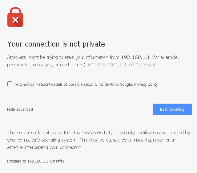
At the login page enter the default pfSense password and username:
| Username: | admin |
|---|---|
| Password: | pfsense |
Click Login to continue
Wizard
Upon successful login, the following is displayed.

Configuring Hostname, Domain Name and DNS Servers
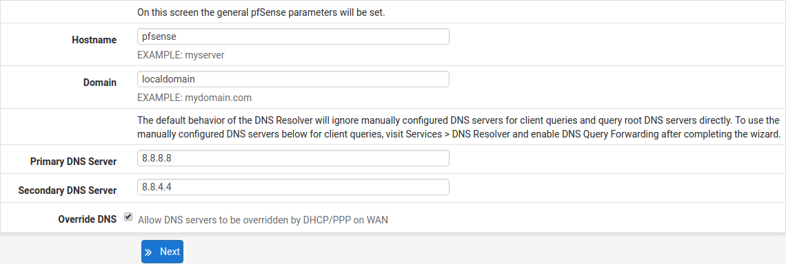
Hostname
For Hostname, any desired name can be entered as it does not affect functionality of the firewall. Assigning a hostname to the firewall will allow the GUI to be accessed by hostname as well as IP address.
For the purposes of this guide, use pfsense for the hostname. The default hostname, pfsense may be left unchanged.
Once saved in the configuration, the GUI may be accessed by entering http://pfsense as well as http://192.168.1.1
Domain
If an existing DNS domain is in use within the local network (such as a Microsoft Active Directory domain), use that domain here. This is the domain suffix assigned to DHCP clients, which should match the internal network.
For networks without any internal DNS domains, enter any desired domain name. The default localdomain is used for the purposes of this tutorial.
DNS Servers
The DNS server fields can be left blank if the DNS Resolver is used in non- forwarding mode, which is the default behavior. The settings may also be left blank if the WAN connection is using DHCP, PPTP or PPPoE types of Internet connections and the ISP automatically assigns DNS server IP addresses. When using a static IP on WAN, DNS server IP addresses must be entered here for name resolution to function if the default DNS Resolver settings are not used.
DNS servers can be specified here even if they differ from the servers assigned by the ISP. Either enter the IP addresses provided by the ISP, or consider using Google public DNS servers (8.8.8.8, 8.8.4.4). Google DNS servers are used for the purpose of this tutorial. Click Next after filling in the fields as appropriate.
Time Server Configuration

Time Server Synchronization
Setting time server synchronization is quite simple. We recommend using the default pfSense time server address, which will randomly select an NTP server from a pool.
Setting Time Zone
Select an appropriate time zone for the location of the firewall. For purposes of this manual, the Timezone setting will be set to America/Chicago for US Central time.
Configuring Wide Area Network (WAN) Type
The WAN interface type is the next to be configured. The IP address assigned to this section becomes the Public IP address that this network will use to communicate with the Internet.

This depicts the four possible WAN interface types. Static, DHCP, PPPoE and PPTP. One must be selected from the drop-down list.
Further information from the ISP is required to proceed when selecting Static, PPPoE and PPTP such as login name and password or as with static addresses, an IP address, subnet mask and gateway address.
DHCP is the most common type of interface for home cable modems. One dynamic IP address is issued from the ISP DHCP server and will become the public IP address of the network behind this firewall. This address will change periodically at the discretion of the ISP. Select DHCP as shown and proceed to the next section.
MAC Address

If replacing an existing firewall, the WAN MAC address of the old firewall may be entered here, if it can be determined. This can help avoid issues involved in switching out firewalls, such as ARP caches, ISPs locking to single MAC addresses, etc.
If the MAC address of the old firewall cannot be located, the impact is most likely insignificant. Power cycle the ISP router and modem and the new MAC address will usually be able to get online. For some ISPs, it may be necessary to call them when switching devices, or an activation process may be required.
Configuring MTU and MSS

MTU or Maximum Transmission Unit determines the largest protocol data unit that can be passed onwards. A 1500-byte packet is the largest packet size allowed by Ethernet at the network layer and for the most part, the Internet so leaving this field blank allows the system to default to 1500-byte packets. PPPoE is slightly smaller at 1492-bytes. Leave this blank for a basic configuration.
Configuring DHCP Hostname

Some ISPs specifically require a DHCP Hostname entry. Unless the ISP requires the setting, leave it blank.
Configuring PPPoE and PPTP Interfaces
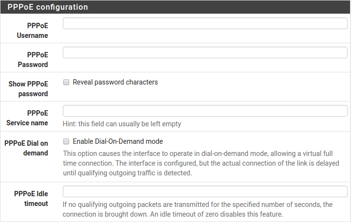
Information added in these sections is assigned by the ISP. Configure these settings as directed by the ISP
Block Private Networks and Bogons
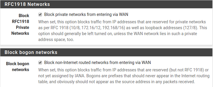
When enabled, all private network traffic originating on the internet is blocked.
Private addresses are reserved for use on internal LANs and blocked from outside traffic so these address ranges may be reused by all private networks.
The following inbound address Ranges are blocked by this firewall rule:
10.0.0.1to10.255.255.255172.16.0.1to172.31.255.254192.168.0.1to192.168.255.254127.0.0.0/8100.64.0.0/10fc00::/7
Bogons are public IP addresses that have not yet been allocated, so they may typically also be safely blocked as they should not be in active use.
Check Block RFC1918 Private Networks and Block Bogon Networks.
Click Next to continue.
Configuring LAN IP Address & Subnet Mask

A static IP address of 192.168.1.1 and a subnet mask (CIDR) of 24 was chosen for this installation. If there are no plans to connect this network to any other network via ×××, the 192.168.1.x default is sufficient.
Click Next to continue.
Note
If a Virtual Private Network (×××) is configured to remote locations, choose a private IP address range more obscure than the very common 192.168.1.0/24. IP addresses within the 172.16.0.0/12 RFC1918 private address block are the least frequently used. We recommend selecting a block of addresses between 172.16.x.x and 172.31.x.x for least likelihood of having ××× connectivity difficulties. An example of a conflict would be If the local LAN is set to 192.168.1.x and a remote user is connected to a wireless hotspot using 192.168.1.x (very common), the remote client won’t be able to communicate across the ××× to the local network.
Change Administrator Password
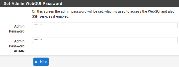
Select a new Administrator Password and enter it twice, then click Next to continue.
Save Changes

Click Reload to save configuration.
Basic Firewall Configured

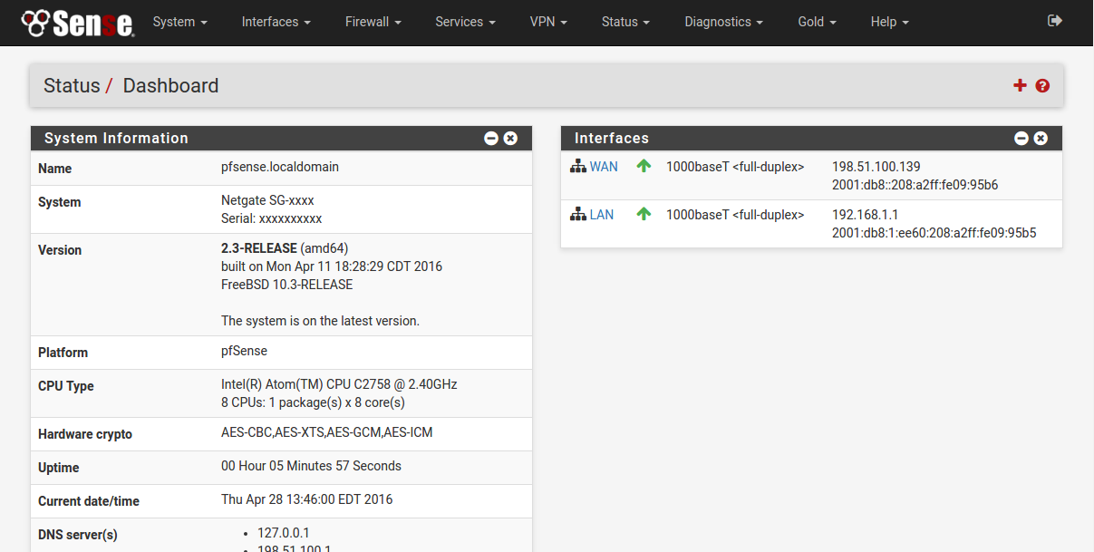
To proceed to the webConfigurator, make the selection as highlighted. The Dashboard display will follow.
Backing Up and Restoring
At this point, basic LAN and WAN interface configuration is complete. Before proceeding, backup the firewall configuration. From the menu at the top of the page, browse to Diagnostics > Backup/Restore.
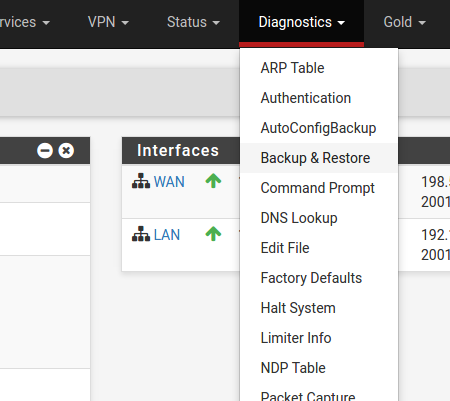
Click Download Configuration and save a copy of the firewall configuration.
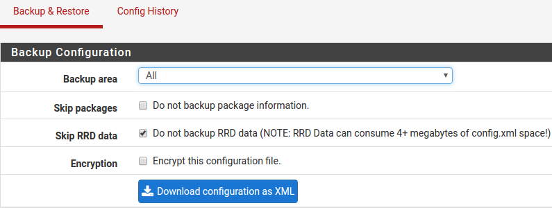
This configuration can be restored from the same screen by choosing the backup file under Restore configuration.
Connecting to the Console
There are times when accessing the console is required. Perhaps GUI console access has been locked out, or the password has been lost or forgotten.
See also
Connect to the console. Cable is required.
Tip
Included with each appliance is a one year subscription to pfSense Gold (Video tutorials, 700+ pages of premium online documentation, and more).
Connecting to Console Port
Simple Configuration
Below are the simple instructions for connecting to the console port with Microsoft Windows. If these steps do not work for you or if you’re an operating system other than Windows, then please skip forward to Advanced Configuration.
Serial Terminal Emulation Client
A serial terminal emulation program is required to access the pfSense appliance console through the serial interface. Microsoft Windows no longer includes HyperTerminal in Versions 7 and up. PuTTY is free and can be downloaded from:
http://www.chiark.greenend.org.uk/~sgtatham/putty/download.html
Configuring Serial Terminal Emulator
PuTTY must be configured to communicate with the pfSense appliance. In order to do so, you must first know what COM Port your computer has assigned to your serial port. Even if you assigned your serial port to COM1 in the BIOS, Windows may remap it to a different COM Port. To determine this, you must open Windows Device Manager and view the COM port assignment.
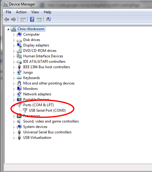
Open PuTTY and locate the Session display as shown. Set the COM Port to that which is displayed in Windows Device Manager and the Speed to 115200.
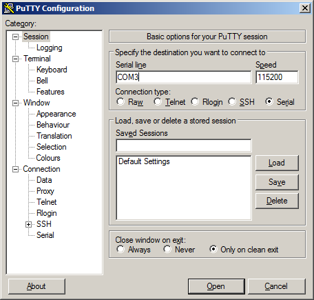
Match the COM Port with what was reported in Windows Device Manager. We will use COM3 for this example. The pfSense appliance serial port speed is 115200 bits per second. The speed of the BIOS and the speed of the console must match so change the speed in PuTTy to 115200bps.
Select Serial as shown and configure the COM Port and Serial Speed as displayed. Select Open and the conolse screen will be displayed.
Advanced Configuration
A Silicon Labs CP210x USB-to-UART bridge is used to provide access to the serial port that acts as a system console. This is exposed via a Micro-USB B port on the front of the case. There are several steps required to access the system console via this port.
Install the Driver
Install an appropriate CP210x USB to UART Bridge VCP (virtual COM port) driver on the workstation used to connect with the system if needed. There are drivers available for Windows, Mac OS X, and Linux available in the Download Software section of the Silicon Labs Website.
Warning
Do not download the SDK, only download the driver.
Note
Recent versions of FreeBSD and many Linux distributions include this driver and will not require manual installation.
Loading the Linux Driver
If the device does not appear automatically, the CP210x driver module may need to be loaded manually, especially if the version of Linux being run is not recent. If the driver was provided with the Linux distribution, run modprobe cp210x as root or using sudo. If it had to be built manually, run insmod ./cp210x.ko assuming the module is in the current directory.
Connect a USB Cable
Next, locate an appropriate USB cable. The type of cable required for the serial console has a Micro-USB B connector on one end and a regular USB (Type A) plug on the other end. These cables are commonly used with smaller USB peripherals such as GPS units, cameras, and so on.
Attach the USB cable between a workstation and the system. Gently push the Mini-B plug end into the console port on the system and connect the USB type A plug into an available USB port on the workstation.
Note
Be certain to gently push in the Mini-B connector on the system side completely. With most cables there will be a tangible “click”, “snap”, or similar indication when the cable is fully engaged.
Locate the Console Port Device
The appropriate device to attach the terminal program to each platform varies by platform and must be located before attempting to connect to the console.
Windows
To locate the device name on Windows, open Device Manager and expand the section for Ports (COM & LPT). Look for an entry with a title such as Silicon Labs CP210x USB to UART Bridge. If there is a label in the name that contains “COMX” where X is a decimal digit (e.g. COM1), that value is what would be used as the port in the terminal program.
Mac OS X
The device associated with the system console is likely to show up as /dev/cu.SLAB_USBtoUART.
Linux
The device associated with the system console is likely to show up as /dev/ttyUSB0. Look for messages about the device attaching in the system log files or by running dmesg.
Note
If the device does not appear in /dev/, see the note above in the driver section about manually loading the Linux driver and then try again.
FreeBSD
The device associated with the system console is likely to show up as /dev/cuaU0. Look for messages about the device attaching in the system log files or by running dmesg.
Launch a Terminal Program
Use a terminal program to connect to the system console port. PuTTY is a popular terminal program that is available on various operating systems. Some other choices of terminal programs:
Linux: screen, PuTTY, minicom, dterm
Mac OS X: screen, ZTerm, cu
Windows: PuTTY, SecureCRT, Do not use Hyperterminal
FreeBSD: screen, cu
The settings to use within the terminal program are:
| Speed: | 115200 baud |
|---|---|
| Data bits: | 8 |
| Parity: | none |
| Stop bits: | 1 |
| Flow Control: | Off or XON/OFF. Hardware flow control (RTS/CTS) must be disabled. |
Client-Specific Examples
PuTTY
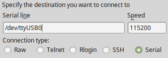
Launch PuTTY and configure it for a Serial type connection with a speed of 115200 using the port name located previously.
Windows Example:

Linux Example:
PuTTY generally handles most cases OK but can have issues with line drawing characters on certain platforms.
These settings seem to work best (tested on Windows):
| Window: | Columns x Rows = 80x24 |
|---|---|
| Window > Appearance: | |
| Font = Courier New 10pt or Consolas 10pt | |
| Window > Translation: | |
| Remote Character Set = Use font encoding or UTF-8 | |
| Window > Translation: | |
| Handling of line drawing characters = Use font in both ANSI and OEM modes or Use Unicode line drawing code points | |
| Window > Colours: | |
| Indicate bolded text by changing = The colour | |
GNU screen
In many cases screen may be invoked simply by using the proper command line:
Mac OS X
sudo screen /dev/cu.SLAB_USBtoUART 115200
Linux
sudo screen /dev/ttyUSB0 115200
FreeBSD
sudo screen /dev/cuaU0 115200
If portions of the text are unreadable but appear to be properly formatted, the most likely culprit is a character encoding mismatch in the terminal. For example, on OS X this is commonly required
sudo screen -U /dev/cu.SLAB_USBtoUART 115200
Adding the -U parameter to the screen command line arguments forces it to use UTF-8 for character encoding.
Troubleshooting
No Serial Output
If there is no output at all, check the following items:
Ensure the cable is correctly attached and fully inserted
Ensure the terminal program is using the correct port
Ensure the terminal program is configured for the correct speed. The default BIOS speed is 115200, and many other modern operating systems use that speed as well. Some older operating systems or custom configurations may use slower speeds such as 9600 or 38400.
Ensure the operating system is configured for the proper console (e.g.
ttyS1in Linux). Consult the various operating install guides on this site for further information.
Garbled Serial Output
If the serial output apears to be garbled, binary, or random characters check the following items:
Ensure the terminal program is configured for the correct speed. (See “No Serial Output” above)
Ensure the terminal program is configured for the proper character encoding, such as UTF-8 or Latin-1, depending on the operating system. (See the previous entry under “GNU screen”)
Serial Output Stops After the BIOS
If serial output is shown for the BIOS but stops afterward, check the following items:
Ensure the terminal program is configured for the correct speed for the installed operating system. (See “No Serial Output” above)
Ensure the installed operating system is configured to activate the serial console.
Ensure the installed operating system is configured for the proper console (e.g.
ttyS1in Linux). Consult the various operating install guides on this site for further information.If booting from a USB flash drive, ensure that the drive was written correctly and contains a bootable operating system image.
Additional Resources
Professional Services
Support does not cover more complex tasks such as CARP configuration for redundancy on multiple firewalls or circuits, network design, and conversion from other firewalls to pfSense. These items are offered as professional services and can be purchased and scheduled accordingly.
Please see https://www.netgate.com/our-services/professional-services.html for more details
Netgate Training
Netgate training offers training courses for increasing your knowledge of pfSense products and services. Whether you need to maintain or improve the security skills of your staff or offer highly specialized support and improve your customer satisfaction; Netgate training has got you covered. Check us out at https://www.netgate.com/training/
Community Support Options
You can find out more information about our active forums, subreddit, IRC, mailing lists and more here: https://www.netgate.com/support/contact-support.html#community-support
Additional Documentation
There is much more that can be accomplished with pfSense software. The best source of information is The pfSense Book, included with the purchace of a Netgate pfSense security gateway appliance.
Monthly hangouts and more are available to those with an active Gold subscription: https://www.netgate.com/our-services/gold-membership.html
Warranty and Support Information
One year manufacturer’s warranty.
Please contact Netgate for warranty information.
All Specifications subject to change without notice
For support information, view our support plans.
Safety and Legal
Contents
Safety Notices
Read, follow, and keep these instructions.
Heed all warnings.
Only use attachments/accessories specified by the manufacturer
Warning
Do not use this product in location that can be submerged by water.
Warning
Do not use this product during an electrical storm to avoid electrical shock.
Electrical Safety Information
Compliance is required with respect to voltage, frequency, and current requirements indicated on the manufacturer’s label. Connection to a different power source than those specified may result in improper operation, damage to the equipment or pose a fire hazard if the limitations are not followed.
There are no operator serviceable parts inside this equipment. Service should be provided only by a qualified service technician.
This equipment is provided with a detachable power cord which has an integral safety ground wire intended for connection to a grounded safety outlet.
Do not substitute the power cord with one that is not the provided approved type. If a 3 prong plug is provided, never use an adapter plug to connect to a 2-wire outlet as this will defeat the continuity of the grounding wire.
The equipment requires the use of the ground wire as a part of the safety certification, modification or misuse can provide a shock hazard that can result in serious injury or death.
Contact a qualified electrician or the manufacturer if there are questions about the installation prior to connecting the equipment.
Protective grounding/earthing is provided by Listed AC adapter. Building installation shall provide appropriate short-circuit backup protection.
Protective bonding must be installed in accordance with local national wiring rules and regulations.
FCC Compliance
Changes or modifications not expressly approved by the party responsible for compliance could void the user’s authority to operate the equipment. This device complies with Part 15 of the FCC Rules. Operation is subject to the following two conditions: 1. This device may not cause harmful interference, and 2. This device must accept any interference received, including interference that may cause undesired operation. NOTE: This equipment has been tested and found to comply with the limits for a Class A digital device, pursuant to part 15 of the FCC Rules. These limits are designed to provide reasonable protection against harmful interference when the equipment is operated in a commercial environment. This equipment generates, uses, and can radiate radio frequency energy and, if not installed and used in accordance with the instruction manual, may cause harmful interference to radio communications. Operations of this equipment in a residential area is likely to cause harmful interference in which case the user will be required to correct the interference at his own expense.
Industry Canada
This Class A digital apparatus complies with Canadian ICES-3(B). Cet appareil numérique de la classe A est conforme à la norme NMB-(3)B Canada.
Australia and New Zealand
Warning
This is a Class A product. In a domestic environment this product may cause radio interference in which case the user may be required to take adequate measures.
CE Marking
CE marking on this product represents the product is in compliance with all directives that are applicable to it.
RoHS/WEEE Compliance Statement
English
European Directive 2002/96/EC requires that the equipment bearing this symbol on the product and/or its packaging must not be disposed of with unsorted municipal waste. The symbol indicates that this product should be disposed of separately from regular household waste streams. It is your responsibility to dispose of this and other electric and electronic equipment via designated collection facilities appointed by the government or local authorities. Correct disposal and recycling will help prevent potential negative consequences to the environment and human health. For more detailed information about the disposal of your old equipment, please contact your local authorities, waste disposal service, or the shop where you purchased the product.
Deutsch
Die Europische Richtlinie 2002/96/EC verlangt, dass technische Ausrüstung, die direkt am Gert und/oder an der Verpackung mit diesem Symbol versehen ist, nicht zusammen mit unsortiertem Gemeindeabfall entsorgt werden darf. Das Symbol weist darauf hin, dass das Produkt von regulrem Haushaltmüll getrennt entsorgt werden sollte. Es liegt in Ihrer Verantwortung, dieses Gert und andere elektrische und elektronische Gerte über die dafür zustndigen und von der Regierung oder rtlichen Behrden dazu bestimmten Sammelstellen zu entsorgen. Ordnungsgemes Entsorgen und Recyceln trgt dazu bei, potentielle negative Folgen für Umwelt und die menschliche Gesundheit zu vermeiden. Wenn Sie weitere Informationen zur Entsorgung Ihrer Altgerte bentigen, wenden Sie sich bitte an die rtlichen Behrden oder stdtischen Entsorgungsdienste oder an den Hndler, bei dem Sie das Produkt erworben haben.
Espaol
La Directiva 2002/96/CE de la UE exige que los equipos que lleven este símbolo en el propio aparato y/o en su embalaje no deben eliminarse junto con otros residuos urbanos no seleccionados. El símbolo indica que el producto en cuestión debe separarse de los residuos domésticos convencionales con vistas a su eliminación. Es responsabilidad suya desechar este y cualesquiera otros aparatos eléctricos y electrónicos a través de los puntos de recogida que ponen a su disposición el gobierno y las autoridades locales. Al desechar y reciclar correctamente estos aparatos estará contribuyendo a evitar posibles consecuencias negativas para el medio ambiente y la salud de las personas. Si desea obtener información más detallada sobre la eliminación segura de su aparato usado, consulte a las autoridades locales, al servicio de recogida y eliminación de residuos de su zona o pregunte en la tienda donde adquirió el producto.
Franais
La directive européenne 2002/96/CE exige que l’équipement sur lequel est apposé ce symbole sur le produit et/ou son emballage ne soit pas jeté avec les autres ordures ménagères. Ce symbole indique que le produit doit être éliminé dans un circuit distinct de celui pour les déchets des ménages. Il est de votre responsabilité de jeter ce matériel ainsi que tout autre matériel électrique ou électronique par les moyens de collecte indiqués par le gouvernement et les pouvoirs publics des collectivités territoriales. L’élimination et le recyclage en bonne et due forme ont pour but de lutter contre l’impact néfaste potentiel de ce type de produits sur l’environnement et la santé publique. Pour plus d’informations sur le mode d’élimination de votre ancien équipement, veuillez prendre contact avec les pouvoirs publics locaux, le service de traitement des déchets, ou l’endroit où vous avez acheté le produit.
Italiano
La direttiva europea 2002/96/EC richiede che le apparecchiature contrassegnate con questo simbolo sul prodotto e/o sull’imballaggio non siano smaltite insieme ai rifiuti urbani non differenziati. Il simbolo indica che questo prodotto non deve essere smaltito insieme ai normali rifiuti domestici. è responsabilità del proprietario smaltire sia questi prodotti sia le altre apparecchiature elettriche ed elettroniche mediante le specifiche strutture di raccolta indicate dal governo o dagli enti pubblici locali. Il corretto smaltimento ed il riciclaggio aiuteranno a prevenire conseguenze potenzialmente negative per l’ambiente e per la salute dell’essere umano. Per ricevere informazioni più dettagliate circa lo smaltimento delle vecchie apparecchiature in Vostro possesso, Vi invitiamo a contattare gli enti pubblici di competenza, il servizio di smaltimento rifiuti o il negozio nel quale avete acquistato il prodotto.
Declaration of Conformity
esky[Czech]
NETGATE tímto prohla uje, e tento NETGATE device, je ve shod se základními po adavky a dal ími p íslu n mi ustanoveními sm rnice 1999/5/ES.
Dansk [Danish]
Undertegnede NETGATE erklrer herved, at flgende udstyr NETGATE device, overholder de vsentlige krav og vrige relevante krav i direktiv 1999/5/EF.
Nederlands [Dutch]
Hierbij verklaart NETGATE dat het toestel NETGATE device, in overeenstemming is met de essentile eisen en de andere relevante bepalingen van richtlijn 1999/5/EG. Bij deze verklaart NETGATE dat deze NETGATE device, voldoet aan de essentile eisen en aan de overige relevante bepalingen van Richtlijn 1999/5/EC.
English
Hereby, NETGATE , declares that this NETGATE device, is in compliance with the essential requirements and other relevant provisions of Directive 1999/5/EC.
Eesti [Estonian]
Kesolevaga kinnitab NETGATE seadme NETGATE device, vastavust direktiivi 1999/5/Eü phinuetele ja nimetatud direktiivist tulenevatele teistele asjakohastele stetele.
Suomi [Finnish]
NETGATE vakuuttaa tten ett NETGATE device, tyyppinen laite on direktiivin 1999/5/EY oleellisten vaatimusten ja sit koskevien direktiivin muiden ehtojen mukainen. Franais [French] Par la présente NETGATE déclare que l’appareil Netgate, device est conforme aux exigences essentielles et aux autres dispositions pertinentes de la directive 1999/5/CE.
Deutsch [German]
Hiermit erklrt Netgate, dass sich diese NETGATE device, in übereinstimmung mit den grundlegenden Anforderungen und den anderen relevanten Vorschriften der Richtlinie 1999/5/EG befindet”. (BMWi)
Ελληνικ [Greek]
ΜΕ ΤΗΝ ΠΑΡΟΥΣΑ NETGATE ΔΗΛΩΝΕΙ ΟΤΙ NETGATE device, ΣΥΜΜΟΡΦΩΝΕΤΑΙ ΠΡΟΣ ΤΙΣ ΟΥΣΙΩΔΕΙΣ ΑΠΑΙΤΗΣΕΙΣ ΚΑΙ ΤΙΣ ΛΟΙΠΕΣ ΣΧΕΤΙΚΕΣ ΔΙΑΤΑΞΕΙΣ ΤΗΣ ΟΔΗΓΙΑΣ 1995/5/ΕΚ.
Magyar [Hungarian]
Alulírott, NETGATE nyilatkozom, hogy a NETGATE device, megfelel a vonatkozó alapvet kvetelményeknek és az 1999/5/EC irányelv egyéb elírásainak.
íslenska [Icelandic]
Hér me l sir NETGATE yfir ví a NETGATE device, er í samrmi vi grunnkrfur og a rar krfur, sem ger ar eru í tilskipun 1999/5/EC.
Italiano [Italian]
Con la presente NETGATE dichiara che questo NETGATE device, è conforme ai requisiti essenziali ed alle altre disposizioni pertinenti stabilite dalla direttiva 1999/5/CE.
Latviski [Latvian]
Ar o NETGATE deklar , ka NETGATE device, atbilst Direkt vas 1999/5/EK b tiskaj m pras b m un citiem ar to saist tajiem noteikumiem.
Lietuvikai [Lithuanian]
NETGATE deklaruoja, kad is NETGATE renginys atitinka esminius reikalavimus ir kitas 1999/5/EB Direktyvos nuostatas.
Malti [Maltese]
Hawnhekk, Netgate, jiddikjara li dan NETGATE device, jikkonforma mal- ti ijiet essenzjali u ma provvedimenti o rajn relevanti li hemm fid-Dirrettiva 1999/5/EC.
Norsk [Norwegian]
NETGATE erklrer herved at utstyret NETGATE device, er i samsvar med de grunnleggende krav og vrige relevante krav i direktiv 1999/5/EF.
Slovensky [Slovak]
NETGATE t mto vyhlasuje, e NETGATE device, sp a základné po iadavky a v etky príslu né ustanovenia Smernice 1999/5/ES.
Svenska [Swedish]
Hrmed intygar NETGATE att denna NETGATE device, str I verensstmmelse med de vsentliga egenskapskrav och vriga relevanta bestmmelser som framgr av direktiv 1999/5/EG.
Espaol [Spanish]
Por medio de la presente NETGATE declara que el NETGATE device, cumple con los requisitos esenciales y cualesquiera otras disposiciones aplicables o exigibles de la Directiva 1999/5/CE.
Polski [Polish]
Niniejszym, firma NETGATE o wiadcza, e produkt serii NETGATE device, spenia zasadnicze wymagania i inne istotne postanowienia Dyrektywy 1999/5/EC.
Português [Portuguese]
NETGATE declara que este NETGATE device, está conforme com os requisitos essenciais e outras disposies da Directiva 1999/5/CE.
Roman [Romanian]
Prin prezenta, NETGATE declar c acest dispozitiv NETGATE este n conformitate cu cerinele eseniale i alte prevederi relevante ale Directivei 1999/5/CE.
Disputes
ANY DISPUTE OR CLAIM RELATING IN ANY WAY TO YOUR USE OF ANY PRODUCTS/SERVICES, OR TO ANY PRODUCTS OR SERVICES SOLD OR DISTRIBUTED BY RCL OR ESF WILL BE RESOLVED BY BINDING ARBITRATION IN AUSTIN, TEXAS, RATHER THAN IN COURT. The Federal Arbitration Act and federal arbitration law apply to this agreement.
THERE IS NO JUDGE OR JURY IN ARBITRATION, AND COURT REVIEW OF AN ARBITRATION AWARD IS LIMITED. HOWEVER, AN ARBITRATOR CAN AWARD ON AN INDIVIDUAL BASIS THE SAME DAMAGES AND RELIEF AS A COURT (INCLUDING INJUNCTIVE AND DECLARATORY RELIEF OR STATUTORY DAMAGES), AND MUST FOLLOW THE TERMS OF THESE TERMS AND CONDITIONS OF USE AS A COURT WOULD.
To begin an arbitration proceeding, you must send a letter requesting arbitration and describing your claim to the following:
Rubicon Communications LLC Attn.: Legal Dept. 7212 McNeil Drive, Suite 204 Austin, Texas 78729legal@netgate.com
The arbitration will be conducted by the American Arbitration Association (AAA) under its rules. The AAA’s rules are available at www.adr.org. Payment of all filing, administration and arbitrator fees will be governed by the AAA’s rules.
We each agree that any dispute resolution proceedings will be conducted only on an individual basis and not in a class, consolidated or representative action. We also both agree that you or we may bring suit in court to enjoin infringement or other misuse of intellectual property rights.
Applicable Law
By using any Products/Services, you agree that the Federal Arbitration Act, applicable federal law, and the laws of the state of Texas, without regard to principles of conflict of laws, will govern these terms and conditions of use and any dispute of any sort that might arise between you and RCL and/or ESF. Any claim or cause of action concerning these terms and conditions or use of the RCL and/or ESF website must be brought within one (1) year after the claim or cause of action arises. Exclusive jurisdiction and venue for any dispute or claim arising out of or relating to the parties’ relationship, these terms and conditions, or the RCL and/or ESF website, shall be with the arbitrator and/or courts located in Austin, Texas. The judgment of the arbitrator may be enforced by the courts located in Austin, Texas, or any other court having jurisdiction over you.
Site Policies, Modification, and Severability
Please review our other policies, such as our pricing policy, posted on our websites. These policies also govern your use of Products/Services. We reserve the right to make changes to our site, policies, service terms, and these terms and conditions of use at any time.
Miscellaneous
If any provision of these terms and conditions of use, or our terms and conditions of sale, are held to be invalid, void or unenforceable, the invalid, void or unenforceable provision shall be modified to the minimum extent necessary in order to render it valid or enforceable and in keeping with the intent of these terms and conditions. If such modification is not possible, the invalid or unenforceable provision shall be severed, and the remaining terms and conditions shall be enforced as written. Headings are for reference purposes only and in no way define, limit, construe or describe the scope or extent of such section. Our failure to act with respect to a breach by you or others does not waive our right to act with respect to subsequent or similar breaches. These terms and conditions set forth the entire understanding and agreement between us with respect to the subject matter hereof, and supersede any prior oral or written agreement pertaining thereto, except as noted above with respect to any conflict between these terms and conditions and our reseller agreement, if the latter is applicable to you.
Limited Warranty
DISCLAIMER OF WARRANTIES AND LIMITATION OF LIABILITY
THE PRODUCTS/SERVICES AND ALL INFORMATION, CONTENT, MATERIALS, PRODUCTS (INCLUDING SOFTWARE) AND OTHER SERVICES INCLUDED ON OR OTHERWISE MADE AVAILABLE TO YOU THROUGH THE PRODUCTS/SERVICES ARE PROVIDED BY US ON AN “AS IS” AND “AS AVAILABLE” BASIS, UNLESS OTHERWISE SPECIFIED IN WRITING. WE MAKE NO REPRESENTATIONS OR WARRANTIES OF ANY KIND, EXPRESS OR IMPLIED, AS TO THE OPERATION OF THE PRODUCTS/SERVICES, OR THE INFORMATION, CONTENT, MATERIALS, PRODUCTS (INCLUDING SOFTWARE) OR OTHER SERVICES INCLUDED ON OR OTHERWISE MADE AVAILABLE TO YOU THROUGH THE PRODUCTS/SERVICES, UNLESS OTHERWISE SPECIFIED IN WRITING. YOU EXPRESSLY AGREE THAT YOUR USE OF THE PRODUCTS/SERVICES IS AT YOUR SOLE RISK.
TO THE FULL EXTENT PERMISSIBLE BY APPLICABLE LAW, RUBICON COMMUNICATIONS, LLC (RCL) AND ELECTRIC SHEEP FENCING (ESF) DISCLAIM ALL WARRANTIES, EXPRESS OR IMPLIED, INCLUDING, BUT NOT LIMITED TO, IMPLIED WARRANTIES OF MERCHANTABILITY AND FITNESS FOR A PARTICULAR PURPOSE. RCL AND ESF DO NOT WARRANT THAT THE PRODUCTS/SERVICES, INFORMATION, CONTENT, MATERIALS, PRODUCTS (INCLUDING SOFTWARE) OR OTHER SERVICES INCLUDED ON OR OTHERWISE MADE AVAILABLE TO YOU THROUGH THE PRODUCTS/SERVICES, RCL’S OR ESF’S SERVERS OR ELECTRONIC COMMUNICATIONS SENT FROM RCL OR ESF ARE FREE OF VIRUSES OR OTHER HARMFUL COMPONENTS. RCL AND ESF WILL NOT BE LIABLE FOR ANY DAMAGES OF ANY KIND ARISING FROM THE USE OF ANY PRODUCTS/SERVICES, OR FROM ANY INFORMATION, CONTENT, MATERIALS, PRODUCTS (INCLUDING SOFTWARE) OR OTHER SERVICES INCLUDED ON OR OTHERWISE MADE AVAILABLE TO YOU THROUGH ANY PRODUCTS/SERVICES, INCLUDING, BUT NOT LIMITED TO DIRECT, INDIRECT, INCIDENTAL, PUNITIVE, AND CONSEQUENTIAL DAMAGES, UNLESS OTHERWISE SPECIFIED IN WRITING.
IN NO EVENT WILL RCL’S OR ESF’S LIABILITY TO YOU EXCEED THE PURCHASE PRICE PAID FOR THE PRODUCT OR SERVICE THAT IS THE BASIS OF THE CLAIM.
CERTAIN STATE LAWS DO NOT ALLOW LIMITATIONS ON IMPLIED WARRANTIES OR THE EXCLUSION OR LIMITATION OF CERTAIN DAMAGES. IF THESE LAWS APPLY TO YOU, SOME OR ALL OF THE ABOVE DISCLAIMERS, EXCLUSIONS, OR LIMITATIONS MAY NOT APPLY TO YOU, AND YOU MIGHT HAVE ADDITIONAL RIGHTS.
SG-1000 FAQ
The following list contains common questions about the SG-1000 asked by customers. The answers cover a wide range of topics
Contents
How do I restore the firewall OS? (firmware)
Download the installation media from https://portal.pfsense.org/firmware/sg-1000/
Remove the power cable from the SG-1000
From there, there are two potential paths:
If the SG-1000 eMMC contains a pfSense 2.4 image from December 29th, 2016 or later it includes a boot environment capable of booting from the USB OTG port. This version of U-Boot identifies itself as
U-Boot 2016.03 (Dec 28 2016 - 11:09:45 -0600):
Write the installer to a USB memory stick using the procedure at Writing an OS Installation Image to Flash Media
Connect the memory stick to the USB OTG port using a USB OTG adapter cable
If the SG-1000 eMMC was running an older version of pfSense 2.4 or the USB OTG port does not allow the firewall to boot, use the SD card recovery method:
Remove the single case screw from the bottom of the firewall
Slide off the case cover
Locate the Micro-SD card socket between the power barrel connector and one the of the network ports
Unlock the Micro-SD card socket cover by sliding the cover toward the network port and then lift it up
Place the Micro-SD card into the socket, contacts down, fitting it into place gently
Gently close the lid. If the lid does not close easily, the card may be misaligned. Check the alignment and try again.
Lock the cover by sliding it toward the power connector until it locks in place
Write the installer to a Micro-SD card using the procedure at Writing an OS Installation Image to Flash Media
Disconnect all cables from the SG-1000 (power, console, network, OTG)
Open the SG-1000 and insert the SD card
Replace the cover and fasten it back in place
Connect to the console as described in Connecting to Console Port
Connect power to the SG-1000
Follow the on-screen instructions
When prompted to reboot, remove the power cable from the SG-1000
If the SG-1000 was booted from USB OTG, unplug the USB OTG cable
If the SG-1000 was booted from SD card, remove the SD card by reversing the procedure above, and then close and refasten the case
Plug the power cable back into the SG-1000
At this point the SG-1000 is ready for use. Connect to it and configure the firewall or restore a configuration as needed.
How do I reset to factory defaults?
There are several methods that can be utilized to reset the configuration back to factory defaults:
From the SG-1000 web interface, visit Diagnostics > Factory Defaults
From SSH, use menu option
4From the serial console menu, use menu option
4
For information about connecting to the serial console, see Connecting to Console Port
If none of those methods work, reinstall the OS image as described above in How do I restore the firewall OS? (firmware)
Note
Resetting the unit to factory defaults only affects the configuration of the firewall and not the contents of the filesystem, which are only reset by reinstalling the OS.
Is the CPU temperature too high?
Initial builds of the SG-1000 displayed temperature output from an inaccurate sensor, which could be off by as much as 10.8 C (50 F), high or low. This sensor was not intended to be used by end-users, only for factory and test measurements. We had hoped it would be accurate enough to be useful, but it was not. Due to the unreliable nature of the sensor, the temperature output is not displayed in current builds.
The SG-1000 is passively cooled (no fans) and it will be warm to the touch. The firewall must be placed so it has adequate room for air to flow around the case.
What should my speed test results be?
We are continually improving the drivers and making other optimizations to increase the speed of the SG-1000. With a basic firewall setup we have shown it can pass around 130Mbit/s. In other conditions, the speed may be higher or lower depending on the firewall configuration, enabled features, environment and testing methods.
Is booting from USB OTG supported?
Yes, provided that the eMMC contains a pfSense operating system image from December 29th, 2016 or later. After that date, the OS contains an updated U-Boot environment which is capable of booting from the USB OTG port.
If the eMMC is completely blank/empty, the SG-1000 cannot boot from the USB OTG port and must be booted from the SD card socket.
What packages are available?
Nearly all packages available for pfSense are available for the SG-1000! There are a few packages that are unable to run on the SG-1000, however. These packages either have requirements that exceed the specification of the SG-1000 or they do not currently compile for the architecture used by the SG-1000 (armv6).
As of January 5th, 2016 the list of available packages on an SG-1000 is:
apcupsd
arping
AutoConfigBackup
Avahi
aws-wizard
Backup
bind
cellular
Cron
darkstat
FTP_Client_Proxy
haproxy
iftop
iperf
ipsec-profile-wizard
LADVD
Lightsquid
mailreport
mtr-nox11
nmap
Notes
nrpe
nut
OpenBGPD
open***-client-export
pfBlockerNG
Quagga_OSPF
routed
RRD_Summary
Service_Watchdog
Shellcmd
siproxd
softflowd
squid
squidGuard
Status_Traffic_Totals
sudo
syslog-ng
System_Patches
tftpd
tinc
zabbix-agent
zabbix-proxy
This list is subject to change.
Note
Some of these packages may install but not fully function at this time, as we are still evaluating their usefulness and reliability.
Why isn’t “my favorite package” available?
Some packages will not compile for the SG-1000 architecture, they exceed the hardware requirements and platform purpose, or they are intended for hardware or uses not possible on the SG-1000.
As of January 5th, 2016 the list of packages that have been excluded from the SG-1000 is:
blinkled
freeradius2
gwled
LCDproc
ntopng
Open-VM-Tools
snort
suricata
Why did you ship BETA firmware?
The SG-1000 is our first firwall that uses an ARM architecture. ARM support required a base operating system of FreeBSD 11 to function acceptably. pfSense 2.4 is based on FreeBSD 11 and is nearing completion, so it was a perfect fit. Though the firmware is labeled “BETA” it has proven to be very stable with only a few minor items remaining to be addressed before its release.
Rather than hold back the delivery of the SG-1000, we decided to ship it once we were satisfied with the stability of the operating system on the SG-1000.
There are components in the way. How do I install a Micro-SD card?
The Micro-SD card socket uses a sliding lock cover, not a push-style mechanism.
To install a Micro-SD card:
Gently slide the cover toward the network interface port to unlock it
Raise the lid
Place the Micro-SD card in the socket, contacts down
Gently close the lid
Slide the cover toward the power connector to lock it in place
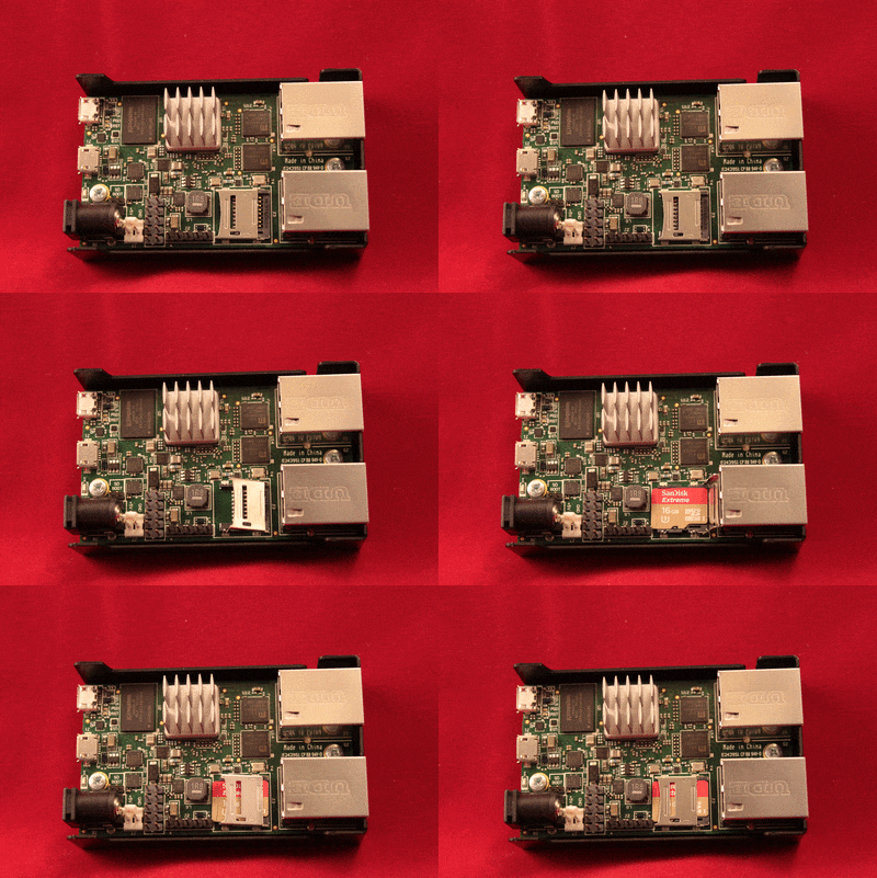
Installing a Micro-SD card in the SG-1000
Tip
If the cover will not close gently, check the alignment of the Micro-SD card as it may not be settled completely into the socket in the correct place.
Why do I see failure messages in the BIOS output while booting?
The U-Boot environment used by the SG-1000 prints error messages that can look concerning but are quite normal, depending on the components installed in or connected to the SG-1000.
Note that both eMMC and Micro-SD cards are all considered “MMC” as they are Multi-Media Cards. eMMC is embedded on the system board, and Micro-SD cards are a removable type of MMC.
The boot environment might state “bad device” but that only indicates that the device is not bootable, it is not a comment about the status of the hardware component.
The following messages are normal without an Micro-SD card present
Card did not respond to voltage select!
*** Warning - MMC init failed, using default environment
** Bad device mmc 0 **
In this case, there is no Micro-SD card present so it could not be initialized or used as a boot device.
The following messages are normal when booting from an SD card without a boot environment on the eMMC
Card doesn't support part_switch
MMC partition switch failed
*** Warning - MMC partition switch failed, using default environment
** Unable to read "u-boot.env" from mmc0:1 **
The following messages are normal when the boot environment supports booting from the USB OTG port, but there is no bootable media connected to the OTG port
** Bad device usb 0 **
The boot environment on eMMC is corrupted and it will not boot from Micro-SD
If the boot environment is present on the eMMC but it is broken in some way, the SG-1000 may not be able to boot from a Micro-SD card. In this case, with a bootable Micro-SD card installed, short the “SD BOOT” header using a jumper (not provided). The “SD BOOT” jumper header is located next to the power connector. After reinstalling the operating system, remove the Micro-SD card and the jumper.
I have an issue with pfSense that’s not covered in FAQ, what do I do?
Please file a bug using our bug reporting guidelines so our developers can troubleshoot the issue.
转载于:https://blog.51cto.com/fxn2025/1966353




 4万+
4万+


 被折叠的 条评论
为什么被折叠?


