上篇我们只是对ospf协议进行初步的认识和了解,我们可以根据ospf协议的基础知识进行一些实验,是我们真的理解ospf协议的真正含义及应用。
我们就以cisio路由器为例,做下面是各种案例:
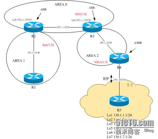
①OSPF的规则、存根、完全存根以及NSSA区域案例
拓扑图:
Cisco路由器支持多种区域类型(规则、存根、完全存根以及NSSA区域),区域类型之间的不同表现在区域允许的LSA类型的不同。
在规则区域中,允许所有类型的LSA。其好处就是所有的路由器都有所有的路由信息,因此具有到达目的地的最佳路径。缺点就是,任何区域外的链路失效将引起局部的SPF计算。
在存根区域中(Stub)中,不允许外部的LSA。因此,ABR不产生任何更新。外部LSA用于描述OSPF区域外的目的地。例如,从其他路由协议接收到的路由,比如RIP,以及重分布到OSPF中的路由将被认为是外部的,并将在一个外部LSA中被通告。
虽然存根区域可以防止外部区域对区域的影响,但它们并不阻止区域内对区域的影响。因为仍然允许汇总LSA,所以,其他区域将仍然影响到存根区域。
完全存根区域(Totally Stub)区域同存根区域类似,将阻止外部LSA。但是,同存根区域不同的是,完全存根区域不允许汇总LSA。这样其他区域将不影响完全存根区域。
NSSA区域同存根区域类似,但是,它可以将外部路由导入到区域中。区域间的路由为类型7的LSA,并被ABR转换为类型5的LSA。例如,如 果你需要阻止外部LSA进入该区域,但仍需要向区域外部发送外部LSA(例如,如果区域中的某个路由器为ASBR),就需要使用NSSA区域。
基本配置如下:
// R1 //
int e0/0
ip ad 192.1.1.1 255.255.255.252
router os 1
network 192.1.1.1 0.0.0.0 area 1
// R2 //
int e0/0
ip ad 192.1.1.2 255.255.255.252
int lo0
ip ad 193.1.1.129 255.255.255.192
ip ospf network point-to-point //变主机路由为网段路由
int e1/0
ip ad 193.1.1.2 255.255.255.128
router os 1
network 192.1.1.2 0.0.0.0 area 1
network 193.1.1.129 0.0.0.0 area 0
network 193.1.1.2 0.0.0.0 area 0
area 0 range 193.1.1.0 255.255.255.0 //区域汇总
// R3 //
int e1/0
ip ad 193.1.1.3 255.255.255.128
int lo0
ip ad 193.1.1.193 255.255.255.192
ip ospf network point-to-point //变主机路由为网段路由
int e0/0
ip ad 194.1.1.1 255.255.255.252
router os 1
network 193.1.1.3 0.0.0.0 area 0
network 193.1.1.193 0.0.0.0 area 0
network 194.1.1.1 0.0.0.0 area 2
area 0 range 193.1.1.0 255.255.255.0 //区域汇总
// R4 //
int e0/0
ip ad 194.1.1.2 255.255.255.252
int e1/0
ip ad 130.1.4.4 255.255.255.0
rotuer os 1
netw 194.1.1.2 0.0.0.0 area 2
summary-address 130.1.0.0 255.255.248.0 //外部路由汇总
router rip
netw 130.1.0.0
// R5 //
int e1/0
ip ad 130.1.4.5 255.255.255.0
int lo1
ip ad 130.1.1.1 255.255.255.0
int lo2
ip ad 130.1.2.1 255.255.255.0
int lo3
ip ad 130.1.3.1 255.255.255.0
int lo5
ip ad 130.1.5.1 255.255.255.0
int lo6
ip ad 130.1.6.1 255.255.255.0
int lo7
ip ad 130.1.7.1 255.255.255.0
router rip
network 130.1.0.0
基本配置完成后,先进行验证:
r1#sh ip ro
130.1.0.0/21 is subnetted, 1 subnets
O E2 130.1.0.0 [110/10] via 192.1.1.2, 00:00:02, Ethernet0/0
O IA 193.1.1.0/24 [110/11] via 192.1.1.2, 00:00:02, Ethernet0/0
192.1.1.0/30 is subnetted, 1 subnets
C 192.1.1.0 is directly connected, Ethernet0/0
194.1.1.0/30 is subnetted, 1 subnets
O IA 194.1.1.0 [110/30] via 192.1.1.2, 00:00:02, Ethernet0/0我们观察到了区域间路由以及外部路由。这时候其它区域的路由波动会引起本地区域的路由重新计算。外部路由同样也会引起内部路由计算。第一个实验,我们要进行区域设置,按图例将各区域分别设置为stub,nssa。只需在各区域边界路由器上加一条命令即可。观察设置区域前后的不同。// R1 // area 1 stub// R2 // area 1 stub// R3 //area 2 nssa// R4 //area 2 nssa
配置完成后我们比较一下结果:
r1#sh ip ro
O IA 193.1.1.0/24 [110/11] via 192.1.1.2, 00:00:13, Ethernet0/0
192.1.1.0/30 is subnetted, 1 subnets
C 192.1.1.0 is directly connected, Ethernet0/0
194.1.1.0/30 is subnetted, 1 subnets
O IA 194.1.1.0 [110/30] via 192.1.1.2, 00:00:13, Ethernet0/0
O*IA 0.0.0.0/0 [110/11] via 192.1.1.2, 00:00:13, Ethernet0/0
注意,R1中不再有到130.1.0.0的OSPF外部路由,相反,添加了一个缺省路由。但是,仍然存在两个内部路由,因为stub区域并不阻止内部区域更新。
下面我们说明一下如何配置区域,以阻止外部LSA的扩散。为了阻止其他区域的汇总LSA影响到本地区域,该区域必须配置为完全存根区域。可以以OSPF进程下添加下列命令:
// R1 //
area 1 stub no-summary
// R2 //
area 1 stub no-summary
验证结果如下:
r1#sh ip ro
192.1.1.0/30 is subnetted, 1 subnets
C 192.1.1.0 is directly connected, Ethernet0/0
O*IA 0.0.0.0/0 [110/11] via 192.1.1.2, 00:00:48, Ethernet0/0
在R1上只出现了一条缺省路由。
注意R3上显示路由表时,只观察到一条N2路由,即外部路由。
r3#sh ip ro
130.1.0.0/21 is subnetted, 1 subnets
O N2 130.1.0.0 [110/10] via 194.1.1.2, 00:17:57, Ethernet0/0
193.1.1.0/24 is variably subnetted, 4 subnets, 3 masks
C 193.1.1.192/26 is directly connected, Loopback0
O 193.1.1.128/26 [110/11] via 193.1.1.2, 00:17:57, Ethernet1/0
O 193.1.1.0/24 is a summary, 00:17:57, Null0
C 193.1.1.0/25 is directly connected, Ethernet1/0
192.1.1.0/30 is subnetted, 1 subnets
O IA 192.1.1.0 [110/20] via 193.1.1.2, 00:01:32, Ethernet1/0
194.1.1.0/30 is subnetted, 1 subnets
C 194.1.1.0 is directly connected, Ethernet0/0
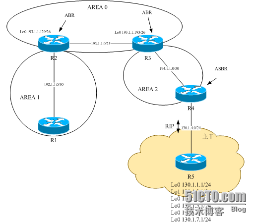
②OSPF区域间、外部路由汇总
拓扑图:
Cisco允许对地址进行汇总,以通过限制区域间通告的路由来达到节省资源的目的。Cisco路由器支持两种类型的地址汇总:区域间汇总和外部路由汇总。区域间汇总用于在区域间汇总地址,而外部汇总用于收集到某个域中的一系列外部路由的汇总。
// R1 //
int e0/0
ip ad 192.1.1.1 255.255.255.252
router os 1
network 192.1.1.1 0.0.0.0 area 1
// R2 //
int e0/0
ip ad 192.1.1.2 255.255.255.252
int e1/0
ip ad 193.1.1.2 255.255.255.128
int lo0
ip ad 193.1.1.129 255.255.255.192
router os 1
network 192.1.1.2 0.0.0.0 area 1
network 193.1.1.2 0.0.0.0 area 0
network 193.1.1.129 0.0.0.0 area 0
// R3 //
int e1/0
ip ad 193.1.1.3 255.255.255.128
int e0/0
ip ad 194.1.1.1 255.255.255.252
int lo0
ip ad 193.1.1.193 255.255.255.192
router os 1
network 193.1.1.193 0.0.0.0 area 0
network 193.1.1.3 0.0.0.0 area 0
network 194.1.1.1 0.0.0.0 area 2
// R4 //
int e0/0
ip ad 194.1.1.2 255.255.255.252
int e1/0
ip ad 130.1.4.4 255.255.255.0
router os 1
network 194.1.1.2 0.0.0.0 area 2
router rip
network 130.1.0.0
// R5 //
int e1/0
ip ad 130.1.4.5 255.255.255.0
int lo1
ip ad 130.1.1.1 255.255.255.0
int lo2
ip ad 130.1.2.1 255.255.255.0
int lo3
ip ad 130.1.3.1 255.255.255.0
int lo5
ip ad 130.1.5.1 255.255.255.0
int lo6
ip ad 130.1.6.1 255.255.255.0
int lo7
ip ad 130.1.7.1 255.255.255.0
router rip
network 130.1.0.0
基本配置完成后,我们首选来验证一下。
r1#sh ip ro
130.1.0.0/24 is subnetted, 7 subnets
O E2 130.1.3.0 [110/10] via 192.1.1.2, 00:00:03, Ethernet0/0
O E2 130.1.2.0 [110/10] via 192.1.1.2, 00:00:03, Ethernet0/0
O E2 130.1.1.0 [110/10] via 192.1.1.2, 00:00:03, Ethernet0/0
O E2 130.1.7.0 [110/10] via 192.1.1.2, 00:00:03, Ethernet0/0
O E2 130.1.6.0 [110/10] via 192.1.1.2, 00:00:03, Ethernet0/0
O E2 130.1.5.0 [110/10] via 192.1.1.2, 00:00:03, Ethernet0/0
O E2 130.1.4.0 [110/10] via 192.1.1.2, 00:00:03, Ethernet0/0
193.1.1.0/24 is variably subnetted, 3 subnets, 2 masks
O IA 193.1.1.192/26 [110/21] via 192.1.1.2, 00:00:48, Ethernet0/0
O IA 193.1.1.128/26 [110/11] via 192.1.1.2, 00:00:48, Ethernet0/0
O IA 193.1.1.0/25 [110/20] via 192.1.1.2, 00:00:48, Ethernet0/0
192.1.1.0/30 is subnetted, 1 subnets
C 192.1.1.0 is directly connected, Ethernet0/0
194.1.1.0/30 is subnetted, 1 subnets
O IA 194.1.1.0 [110/30] via 192.1.1.2, 00:39:39, Ethernet0/0
在我们汇总完成后,上述结果里,红、蓝色显示部分将会被取代。方法如下:
区域间汇总:
// R2 //
router os 1
area 0 range 193.1.1.0 255.255.255.0
// R3 //
router os 1
area 0 range 193.1.1.0 255.255.255.0
外部路由汇总:
// R4 //
router os 1
summary-address 130.1.0.0 255.255.248.0
验证如下:
r1#sh ip ro
130.1.0.0/21 is subnetted, 1 subnets
O E2 130.1.0.0 [110/10] via 192.1.1.2, 00:00:02, Ethernet0/0
O IA 193.1.1.0/24 [110/11] via 192.1.1.2, 00:00:13, Ethernet0/0
192.1.1.0/30 is subnetted, 1 subnets
C 192.1.1.0 is directly connected, Ethernet0/0
194.1.1.0/30 is subnetted, 1 subnets
O IA 194.1.1.0 [110/30] via 192.1.1.2, 00:47:19, Ethernet0/0
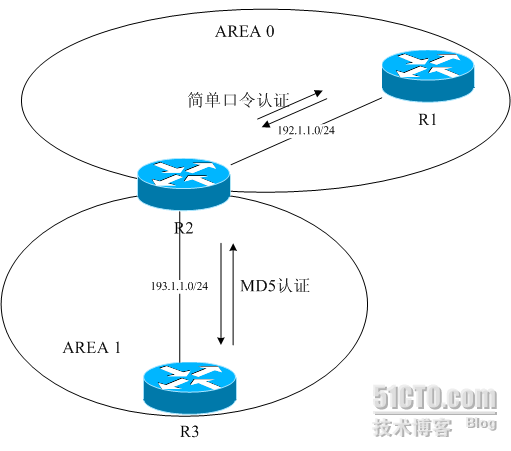
③OSPF邻居认证实际案例
拓扑图:
邻居认证使得路由器确认每次所收到的路由更新的源。如果关键字不匹配,就会拒绝路由更新。
思科使用两种类型的邻居认证:纯文本和MD5。
纯文本认证发一个关键字,这个关键字是明文传输,可被非法用户所窃取,所以不推荐使用。
MD5认证发一个报文摘要,而不是关键字。MD5被用来生成一个关键字的散列。这个散列是被发送的对象。MD5方式不易被非法用户所窃取。
这个案例中,我们在R1与R2之间使用明文认证,在R2与R3之间使用MD5认证。
/ / R1 / /
INT E0 / 0
IP广告192.1.1.1 255.255.255.0
思科IP OSPF认证密钥/ /明文认证,关键字为思科
路由器操作系统1
网络192.1.1.1 0.0.0.0区域0
区域0认证
/ / R2 / /
INT E0 / 0
IP广告192.1.1.2 255.255.255.0
思科IP OSPF认证密钥/ /明文认证,关键字为思科
中期E1 / 0
IP广告193.1.1.2 255.255.255.0
IP OSPF消息摘要键1 MD5饼干
路由器操作系统1
网络192.1.1.2 0.0.0.0区域0
网络193.1.1.2 0.0.0.0面积1
区域0认证
面积1认证信息摘要
/ / R3 / /
中期E1 / 0
IP AD 193.1.1.3 255.255.255.0
IP OSPF消息摘要键1 MD5饼干
路由器操作系统1
网络193.1.1.3 0.0.0.0 1
面积1认证信息摘要
验证过程:
R1#sh的IP OS INT E0 / 0
端口Ethernet0 / 0,线路协议是
互联网地址192.1.1.1/24,面积
1 0 进程ID,路由器ID 192.1.1.1,网络类型广播,成本:10
发送延迟1国家BDR,优先级1
指定路由器193.1.1.2(ID),接口地址192.1.1.2
备份指定路由器192.1.1.1(ID),接口地址192.1.1.1
配置的定时器的时间间隔,你好10,死40 秒,等待40,重发5
您好由于00:00:06
指数1/1,洪水队列长度为0的
下一个0x0的(0)/ 0X0(0)
最近洪水扫描长度为1,最大为1
最后水灾扫描时间为0毫秒,最大为0毫秒
邻居数为1时,相邻的邻居数为1
相邻的邻居193.1.1.2(指定路由器)
抑制打招呼0邻居(次)简单密码认证
R2#SH IP OS INT E0 / 0
端口Ethernet0 / 0,线路协议是
互联网地址192.1.1.2/24,面积
1 0 进程ID,路由器ID 193.1.1.2,网络类型广播,成本:10
发送延迟1国家DR,优先级1
指定路由器193.1.1.2(ID),接口地址192.1.1.2
备份指定路由器(ID)192.1.1.1,接口地址192.1.1.1
配置的定时器的时间间隔,你好10,死40 秒,等待40,重发5
您好○时00分04秒
指数1/1,洪水队列长度为0的
下一个0x0的(0)/ 0X0(0)
最近洪水扫描长度为1,最大为2
最新洪水扫描时间为0毫秒,最大为0毫秒
邻居计数为1,相邻的邻居计数是
相邻的邻居192.1.1.1(备份指定路由器)
禁止为0的邻居打招呼(次)简单密码认证
R2#SH IP OS E1 / 0
以太网1/0,线路协议是
Internet地址的193.1.1.2/24区
进程ID 1路由器ID 193.1.1.2,网络类型广播,成本:10
发送延迟1国家DR,优先级1
指定路由器193.1.1.2(ID),接口地址193.1.1.2
备份指定路由器(ID)193.1.1.3,接口地址193.1.1.3
配置的定时器的时间间隔,你好10,死40 秒,等待40,重发5
你好,由于
指数在0时00分03秒1/2,洪水队列长度为0的
下一个0x0的(0)/ 0X0(0)
最近洪水扫描长度为2,最大的是2
最后水灾扫描时间为0毫秒,最大为0毫秒
邻居数为1时,相邻的邻居数为1
相邻的邻居193.1.1.3(备份指定路由器)
抑制打招呼的邻居(0) 启用消息摘要认证 最年轻的密钥ID为1
R3#sh的IP OS E1 / 0
以太网1/0,线路协议是
Internet地址的193.1.1.3/24区
进程ID 1路由器ID 193.1.1.3,网络类型广播,成本:10
发送延迟1国家BDR,优先级1
指定路由器193.1.1.2(ID),接口地址193.1.1.2
备份指定路由器193.1.1.3(ID),接口地址193.1.1.3
配置的定时器的时间间隔,你好10,死40 秒,等待40,重发5
您好○时00分04秒
指数1/1,洪水队列长度为0的
下一个0x0的(0)/ 0X0(0)
最近洪水扫描长度为1,最大为2
最新洪水扫描时间为0毫秒,最大为0毫秒
邻居计数为1,相邻的邻居数为1
相邻的邻居193.1.1.2(指定路由器)
抑制打招呼 消息摘要认证启用 年纪最小的键ID为1 0邻居(S)
为了更进一步理解认证过程,我们可以打开DEBUG,并将R3的MD5认证键改为5:
/ / R3 / /
调试IP OSPF ADJ
中期E1 / 0
IP OSPF消息摘要键5 MD5饼干
R3#
01:16:03:OSPF:接收封包从193.1.1.2,端口Ethernet1 / 0:不匹配验证密钥-没有消息摘要键1接口
01:16:09:OSPF:发送最年轻的关键5
R3#显示IP OSPF邻居/ /观察结果无法发现邻居。
/ /认证未通过,无法与R2建立起邻居关系。
当我们把MD5认证KEY改回1后,认证通过。
第二步实验,我们把关键字进行修改:
/ / R3 / /
调试IP OSPF ADJ
中期E1 / 0
IP OSPF消息摘要键1 MD5崔健
01:21:33:OSPF:接收封包从193.1.1.2,端口Ethernet1 / 0:不匹配验证密钥-消息摘要密钥1
01:21:40:OSPF:发送,最年轻的关键1
我们要在实际工作中学会使用调试这个思科排错的利器。
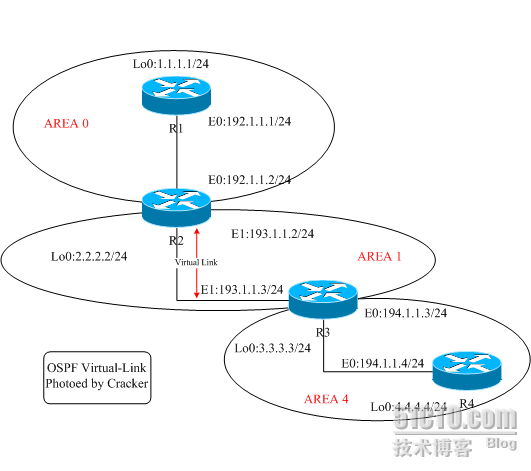
④OSPF虚链路(virtual-link)配置实例
拓扑图:
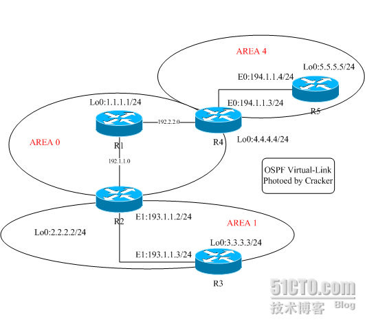
这个配置将验证一个OSPF虚电路(Virtual-Link)的过程,重点在观察虚链路连接的临时网络与正常区域间路由有何区别。上图中区域4(area 4)没有和area 0直接相连。在R2与R3之间配置了一条虚链路。
// R1 //
int lo0
ip ad 1.1.1.1 255.255.255.0
int e0
ip ad 192.1.1.1 255.255.255.0
router os 1
network 192.1.1.0 0.0.0.255 area 0
// R2 //
int lo0
ip ad 2.2.2.2 255.255.255.0
int e0
ip ad 192.1.1.2 255.255.255.0
int e1
ip ad 193.1.1.2 255.255.255.0
router os 1
network 192.1.1.0 0.0.0.255 area 0
network 193.1.1.0 0.0.0.255 area 1
// R3 //
int lo0
ip ad 3.3.3.3 255.255.255.0
int e1
ip ad 193.1.1.3 255.255.255.0
int e0
ip ad 194.1.1.3 255.255.255.0
router os 1
network 193.1.1.0 0.0.0.255 area 1
network 194.1.1.0 0.0.0.255 area 4
// R4 //
int lo0
ip ad 4.4.4.4 255.255.255.0
int e0
ip ad 194.1.1.4 255.255.255.0
router os 1
network 194.1.1.0 0.0.0.255 area 4
基本配置完成后,我们在每台路由器上分别来验证一下:
r1#sh ip os nei
Neighbor ID Pri State Dead Time Address Interface
2.2.2.2 1 FULL/BDR 00:00:33 192.1.1.2 Ethernet0/0
r1#
r1#sh ip ro
1.0.0.0/24 is subnetted, 1 subnets
C 1.1.1.0 is directly connected, Loopback0
O IA 193.1.1.0/24 [110/20] via 192.1.1.2, 00:00:19, Ethernet0/0
C 192.1.1.0/24 is directly connected, Ethernet0/0
//注意R1上有关于193.1.1.0的路由条目,是属于IA类型(域间路由)
r2#sh ip os nei
Neighbor ID Pri State Dead Time Address Interface
1.1.1.1 1 FULL/DR 00:00:35 192.1.1.1 Ethernet0/0
3.3.3.3 1 FULL/BDR 00:00:35 193.1.1.3 Ethernet1/0
r2#
r2#
r2#sh ip ro
2.0.0.0/24 is subnetted, 1 subnets
C 2.2.2.0 is directly connected, Loopback0
C 193.1.1.0/24 is directly connected, Ethernet1/0
C 192.1.1.0/24 is directly connected, Ethernet0/0
r3#sh ip os nei
Neighbor ID Pri State Dead Time Address Interface
2.2.2.2 1 FULL/DR 00:00:32 193.1.1.2 Ethernet1/0
4.4.4.4 1 FULL/DR 00:00:34 194.1.1.4 Ethernet0/0
r3#sh ip ro
3.0.0.0/24 is subnetted, 1 subnets
C 3.3.3.0 is directly connected, Loopback0
C 193.1.1.0/24 is directly connected, Ethernet1/0
O IA 192.1.1.0/24 [110/20] via 193.1.1.2, 00:02:49, Ethernet1/0
C 194.1.1.0/24 is directly connected, Ethernet0/0
//注意R3中有关于192.1.1.0的路由是属于IA类型(域间路由)
r4#sh ip os nei
Neighbor ID Pri State Dead Time Address Interface
3.3.3.3 1 FULL/BDR 00:00:33 194.1.1.3 Ethernet0/0
r4#sh ip ro
4.0.0.0/24 is subnetted, 1 subnets
C 4.4.4.0 is directly connected, Loopback0
C 194.1.1.0/24 is directly connected, Ethernet0/0
//R4上没有关于AREA 0内的任何路由信息
我们下面在R2、R3上添加Virtual-link的配置:
R2:
router os 1
area 1 virtual-link 3.3.3.3
R3:
router os 1
area 1 virtual-link 2.2.2.2
对比之前的路由信息,看有何区别:
r1#sh ip ro
1.0.0.0/24 is subnetted, 1 subnets
C 1.1.1.0 is directly connected, Loopback0
O IA 193.1.1.0/24 [110/20] via 192.1.1.2, 00:00:01, Ethernet0/0
C 192.1.1.0/24 is directly connected, Ethernet0/0
O IA 194.1.1.0/24 [110/30] via 192.1.1.2, 00:00:01, Ethernet0/0
//多了一条194网段的路由,类型IA(区域间)
r2#sh ip ro
2.0.0.0/24 is subnetted, 1 subnets
C 2.2.2.0 is directly connected, Loopback0
C 193.1.1.0/24 is directly connected, Ethernet1/0
C 192.1.1.0/24 is directly connected, Ethernet0/0
O IA 194.1.1.0/24 [110/20] via 193.1.1.3, 00:00:06, Ethernet1/0
//多了一条194网段路由,类型为IA(区域间)
r3#sh ip ro
3.0.0.0/24 is subnetted, 1 subnets
C 3.3.3.0 is directly connected, Loopback0
C 193.1.1.0/24 is directly connected, Ethernet1/0
O 192.1.1.0/24 [110/20] via 193.1.1.2, 00:02:56, Ethernet1/0
C 194.1.1.0/24 is directly connected, Ethernet0/0
//R3的192路由原本为IA类型(区域间),现在转为O类型(区域内),说明R3认为自已与192网段是直连的。虚链路相当于将R3直接连接了AREA 0 与 AREA 4区域
r4#sh ip ro
4.0.0.0/24 is subnetted, 1 subnets
C 4.4.4.0 is directly connected, Loopback0
O IA 193.1.1.0/24 [110/20] via 194.1.1.3, 00:03:40, Ethernet0/0
O IA 192.1.1.0/24 [110/30] via 194.1.1.3, 00:03:25, Ethernet0/0
C 194.1.1.0/24 is directly connected, Ethernet0/0
//R4上192路由类型IA(区域间)
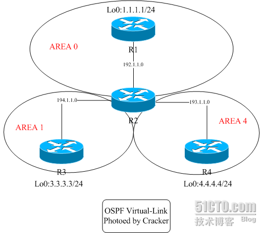
最后我们将虚链路效果再与正常连接方式进行一下比对,如下图:
验证如下:
r1#sh ip ro
1.0.0.0/24 is subnetted, 1 subnets
C 1.1.1.0 is directly connected, Loopback0
O IA 193.1.1.0/24 [110/20] via 192.1.1.2, 00:00:41, Ethernet0/0
C 192.1.1.0/24 is directly connected, Ethernet0/0
C 192.2.2.0/24 is directly connected, Ethernet1/0
O IA 194.1.1.0/24 [110/20] via 192.2.2.4, 00:00:39, Ethernet1/0
r2#sh ip ro
2.0.0.0/24 is subnetted, 1 subnets
C 2.2.2.0 is directly connected, Loopback0
C 193.1.1.0/24 is directly connected, Ethernet1/0
C 192.1.1.0/24 is directly connected, Ethernet0/0
O 192.2.2.0/24 [110/20] via 192.1.1.1, 00:01:04, Ethernet0/0
O IA 194.1.1.0/24 [110/30] via 192.1.1.1, 00:00:03, Ethernet0/0
r2#
r3#sh ip ro
3.0.0.0/24 is subnetted, 1 subnets
C 3.3.3.0 is directly connected, Loopback0
C 193.1.1.0/24 is directly connected, Ethernet1/0
O IA 192.1.1.0/24 [110/20] via 193.1.1.2, 00:01:31, Ethernet1/0
O IA 192.2.2.0/24 [110/30] via 193.1.1.2, 00:01:15, Ethernet1/0
O IA 194.1.1.0/24 [110/40] via 193.1.1.2, 00:00:15, Ethernet1/0
r4#sh ip ro
4.0.0.0/24 is subnetted, 1 subnets
C 4.4.4.0 is directly connected, Loopback0
O IA 193.1.1.0/24 [110/30] via 192.2.2.1, 00:00:39, Ethernet1/0
O 192.1.1.0/24 [110/20] via 192.2.2.1, 00:01:37, Ethernet1/0
C 192.2.2.0/24 is directly connected, Ethernet1/0
C 194.1.1.0/24 is directly connected, Ethernet0/0
r5#sh ip ro
5.0.0.0/24 is subnetted, 1 subnets
C 5.5.5.0 is directly connected, Loopback0
O IA 193.1.1.0/24 [110/40] via 194.1.1.4, 00:00:52, Ethernet0/0
O IA 192.1.1.0/24 [110/30] via 194.1.1.4, 00:00:52, Ethernet0/0
O IA 192.2.2.0/24 [110/20] via 194.1.1.4, 00:00:52, Ethernet0/0
C 194.1.1.0/24 is directly connected, Ethernet0/0
如果上述方式还不容易理解,你也可以将virtual-link可以想象成:将R2与R3合并成一台路由器,如下图:
r1#sh ip ro
1.0.0.0/24 is subnetted, 1 subnets
C 1.1.1.0 is directly connected, Loopback0
O IA 193.1.1.0/24 [110/20] via 192.1.1.2, 00:00:57, Ethernet0/0
C 192.1.1.0/24 is directly connected, Ethernet0/0
O IA 194.1.1.0/24 [110/74] via 192.1.1.2, 00:00:24, Ethernet0/0
r2#sh ip ro
2.0.0.0/24 is subnetted, 1 subnets
C 2.2.2.0 is directly connected, Loopback0
C 193.1.1.0/24 is directly connected, Ethernet1/0
C 192.1.1.0/24 is directly connected, Ethernet0/0
C 194.1.1.0/24 is directly connected, Serial2/0
r3#sh ip ro
3.0.0.0/24 is subnetted, 1 subnets
C 3.3.3.0 is directly connected, Loopback0
C 193.1.1.0/24 is directly connected, Ethernet1/0
O IA 192.1.1.0/24 [110/20] via 193.1.1.2, 00:01:06, Ethernet1/0
O IA 194.1.1.0/24 [110/74] via 193.1.1.2, 00:00:37, Ethernet1/0
r4#sh ip ro
4.0.0.0/24 is subnetted, 1 subnets
C 4.4.4.0 is directly connected, Loopback0
O IA 193.1.1.0/24 [110/74] via 194.1.1.2, 00:00:17, Serial2/0
O IA 192.1.1.0/24 [110/74] via 194.1.1.2, 00:00:17, Serial2/0
C 194.1.1.0/24 is directly connected, Serial2/0
⑤在NBMA网络广播模式下配置OSPF实际案例
拓扑图:
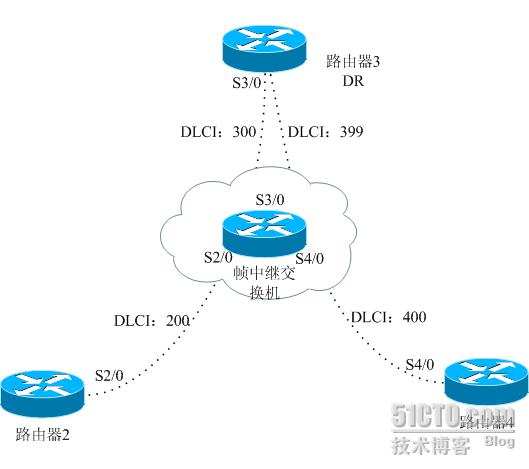
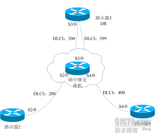
广播式网络是一个渐进的操作过程,它可以定义所有邻居。当给一个接口配置广播时,这个接口就好像是连入了LAN中,网络中仍要选出DR和BDR,需特别保证路由器选出的DR/BDR与网络中所有路由器都有物理连接。使用接口命令ip ospf network broadcast可以向所有路由器上设置网络类型。R2、R4的串行接口被配置成OSPF PRIORITY为0,这将保证R3成为DR。// 帧交换机frame-relay switchingint s2/0 encapsulation frame-relay clock rate 64000 frame-relay intf-type dce frame-relay route 200 int s3/0 300int s3/0 encapsulation frame-relay clock rate 64000 frame-relay intf-type dce frame-relay route 300 int s2/0 200 frame-relay route 399 int s4/0 400int s4/0 encapsulation frame-relay clock rate 64000 frame-relay intf-type dce frame-relay route 400 int s2/0 399// R2 //int lo0 ip ad 2.2.2.2 255.255.255.0int s2/0 encapsulation frame-relayip ospf network broadcast //将OSPF网络类型设置为广播模式ip ospf priority 0 //优先级为0,不参与DR选举 ip ad 192.1.1.2 255.255.255.0 frame-relay map ip 192.1.1.3 200 broadcast frame-relay map ip 192.1.1.4 200 broadcastrouter os 1 network 2.2.2.2 0.0.0.0 area 0 network 192.1.1.2 0.0.0.0 area 0// R3 //int lo0 ip ad 3.3.3.3 255.255.255.0int s3/0 encapsulation frame-relayip ospf network broadcast //将OSPF网络类型设置为广播模式 ip address 192.1.1.3 255.255.255.0 frame-relay map ip 192.1.1.2 300 broadcast frame-relay map ip 192.1.1.4 399 broadcastrouter os 1 network 3.3.3.3 0.0.0.0 area 0 network 192.1.1.3 0.0.0.0 area 0// R4 //int lo0 ip ad 4.4.4.4 255.255.255.0int s4/0 encapsulation frame-relay ip ad 192.1.1.4 255.255.255.0ip ospf network broadcast //将OSPF网络类型设置为广播模式 ip ospf priority 0 //优先级为0,不参与DR选举 frame-relay map ip 192.1.1.2 400 broadcast frame-relay map ip 192.1.1.3 400 broadcastrouter os 1 network 4.4.4.4 0.0.0.0 area 0 network 192.1.1.4 0.0.0.0 area 0验证过程:一、首先来检查DR选举是否按我们的设计,R3被选举为DR,R2、R4不参与选举,同时注意网络类型是否为NBMA,hello时间间隔是否为30秒。。。。。。r3#sh ip os int s3/0
Serial3/0 is up, line protocol is up
Internet Address 192.1.1.3/24, Area 0
Process ID 1, Router ID 3.3.3.3, Network Type BROADCAST, Cost: 64
Transmit Delay is 1 sec, State DR, Priority 1
Designated Router (ID) 3.3.3.3, Interface address 192.1.1.3
No backup designated router on this network
Timer intervals configured, Hello 10, Dead 40, Wait 40, Retransmit 5
Hello due in 00:00:27
Index 2/2, flood queue length 0
Next 0x0(0)/0x0(0)
Last flood scan length is 2, maximum is 2
Last flood scan time is 0 msec, maximum is 0 msec
Neighbor Count is 2, Adjacent neighbor count is 2
Adjacent with neighbor 4.4.4.4
Adjacent with neighbor 2.2.2.2
Suppress hello for 0 neighbor(s)r2#sh ip os int s2/0
Serial2/0 is up, line protocol is up
Internet Address 192.1.1.2/24, Area 0
Process ID 1, Router ID 2.2.2.2, Network Type BROADCAST, Cost: 64
Transmit Delay is 1 sec, State DROTHER, Priority 0
Designated Router (ID) 3.3.3.3, Interface address 192.1.1.3
No backup designated router on this network
Timer intervals configured, Hello 10, Dead 40, Wait 40, Retransmit 5
Hello due in 00:00:06
Index 2/2, flood queue length 0
Next 0x0(0)/0x0(0)
Last flood scan length is 1, maximum is 1
Last flood scan time is 0 msec, maximum is 0 msec
Neighbor Count is 1, Adjacent neighbor count is 1
Adjacent with neighbor 3.3.3.3 (Designated Router)
Suppress hello for 0 neighbor(s)r4#sh ip ospf int s4/0
Serial4/0 is up, line protocol is up
Internet Address 192.1.1.4/24, Area 0
Process ID 1, Router ID 4.4.4.4, Network Type BROADCAST, Cost: 64
Transmit Delay is 1 sec, State DROTHER, Priority 0
Designated Router (ID) 3.3.3.3, Interface address 192.1.1.3
No backup designated router on this network
Timer intervals configured, Hello 10, Dead 40, Wait 40, Retransmit 5
Hello due in 00:00:05
Index 2/2, flood queue length 0
Next 0x0(0)/0x0(0)
Last flood scan length is 1, maximum is 1
Last flood scan time is 0 msec, maximum is 0 msec
Neighbor Count is 1, Adjacent neighbor count is 1
Adjacent with neighbor 3.3.3.3 (Designated Router)
Suppress hello for 0 neighbor(s)
二、接下来观察各路由器邻居建立情况:r2#sh ip os neiNeighbor ID Pri State Dead Time Address Interface
3.3.3.3 1 FULL/DR 00:01:50 192.1.1.3 Serial2/0r3#sh ip os neiNeighbor ID Pri State Dead Time Address Interface
4.4.4.4 0 FULL/DROTHER 00:01:41 192.1.1.4 Serial3/0
2.2.2.2 0 FULL/DROTHER 00:01:30 192.1.1.2 Serial3/0r3#sh ip os neiNeighbor ID Pri State Dead Time Address Interface
3.3.3.3 1 FULL/DR 00:01:48 192.1.1.3 Serial4/0三、最后验证路由:r2#sh ip ro 2.0.0.0/24 is subnetted, 1 subnets
C 2.2.2.0 is directly connected, Loopback0
3.0.0.0/32 is subnetted, 1 subnets
O 3.3.3.3 [110/65] via 192.1.1.3, 00:00:17, Serial2/0
4.0.0.0/32 is subnetted, 1 subnets
O 4.4.4.4 [110/65] via 192.1.1.4, 00:00:17, Serial2/0
C 192.1.1.0/24 is directly connected, Serial2/0r3#sh ip ro 2.0.0.0/32 is subnetted, 1 subnets
O 2.2.2.2 [110/65] via 192.1.1.2, 00:00:38, Serial3/0
3.0.0.0/24 is subnetted, 1 subnets
C 3.3.3.0 is directly connected, Loopback0
4.0.0.0/32 is subnetted, 1 subnets
O 4.4.4.4 [110/65] via 192.1.1.4, 00:00:38, Serial3/0
C 192.1.1.0/24 is directly connected, Serial3/0r4#sh ip ro 2.0.0.0/32 is subnetted, 1 subnets
O 2.2.2.2 [110/65] via 192.1.1.2, 00:01:04, Serial4/0
3.0.0.0/32 is subnetted, 1 subnets
O 3.3.3.3 [110/65] via 192.1.1.3, 00:01:04, Serial4/0
4.0.0.0/24 is subnetted, 1 subnets
C 4.4.4.0 is directly connected, Loopback0
C 192.1.1.0/24 is directly connected, Serial4/0
r4#
如果我们将R2路由器的优先级调整为10,重启后R2将成为DR,R3作为BDR,R4作为DROTHER,这样的结果会导致R4无法收到R2、R3的路由更新,原因如下:
r4#sh ip ospf database
OSPF Router with ID (4.4.4.4) (Process ID 1)
Router Link States (Area 0)
Link ID ADV Router Age Seq# Checksum Link count
2.2.2.2 2.2.2.2 99 0x80000009 0xCF69 2
3.3.3.3 3.3.3.3 109 0x8000000B 0xDF4A 2
4.4.4.4 4.4.4.4 107 0x8000000C 0xFB1F 2
Net Link States (Area 0)
Link ID ADV Router Age Seq# Checksum
192.1.1.2 2.2.2.2 108 0x80000001 0x4910
r4#sh ip os database router
OSPF Router with ID (4.4.4.4) (Process ID 1)
Router Link States (Area 0)
Adv Router is not-reachable
LS age: 124
Options: (No TOS-capability, DC)
LS Type: Router Links
Link State ID: 2.2.2.2
Advertising Router: 2.2.2.2
LS Seq Number: 80000009
Checksum: 0xCF69
Length: 48
Number of Links: 2
Link connected to: a Transit Network
(Link ID) Designated Router address: 192.1.1.2
(Link Data) Router Interface address: 192.1.1.2
Number of TOS metrics: 0
TOS 0 Metrics: 64
Link connected to: a Stub Network
(Link ID) Network/subnet number: 2.2.2.2
(Link Data) Network Mask: 255.255.255.255
Number of TOS metrics: 0
TOS 0 Metrics: 1
Adv Router is not-reachable
LS age: 198
Options: (No TOS-capability, DC)
LS Type: Router Links
Link State ID: 3.3.3.3
Advertising Router: 3.3.3.3
LS Seq Number: 8000000B
Checksum: 0xDF4A
Length: 48
Number of Links: 2
Link connected to: a Transit Network
(Link ID) Designated Router address: 192.1.1.2
(Link Data) Router Interface address: 192.1.1.3
Number of TOS metrics: 0
TOS 0 Metrics: 64
Link connected to: a Stub Network
(Link ID) Network/subnet number: 3.3.3.3
(Link Data) Network Mask: 255.255.255.255
Number of TOS metrics: 0
TOS 0 Metrics: 1
LS age: 215
Options: (No TOS-capability, DC)
LS Type: Router Links
Link State ID: 4.4.4.4
Advertising Router: 4.4.4.4
LS Seq Number: 8000000C
Checksum: 0xFB1F
Length: 48
Number of Links: 2
Link connected to: a Transit Network
(Link ID) Designated Router address: 192.1.1.3
(Link Data) Router Interface address: 192.1.1.4
Number of TOS metrics: 0
TOS 0 Metrics: 64
Link connected to: a Stub Network
(Link ID) Network/subnet number: 4.4.4.4
(Link Data) Network Mask: 255.255.255.255
Number of TOS metrics: 0
TOS 0 Metrics: 1
⑥在NBMA网络点到多点模式下配置OSPF实际案例
拓扑图:
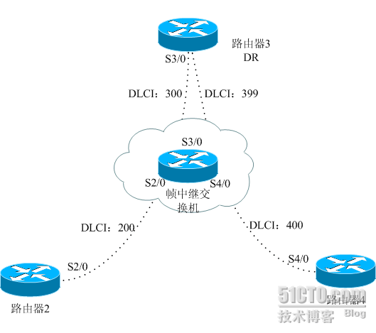
一个点到多点网络被看作若干具有一个或多个邻居的点到点接口。当一个接口被配置给点到多点网络,就不需要DR/BDR,不需要定义邻居,这大大简化了给NBMA网络配置OSPF。
使用端口命令 ip ospa network point-to-multioint可以给所有路由器设置网络类型。既不需要定义邻居,也不需要设置优先级,因为网络中没有DR/BDR。
// 帧交换机
frame-relay switching
int s2/0
encapsulation frame-relay
clock rate 64000
frame-relay intf-type dce
frame-relay route 200 int s3/0 300
int s3/0
encapsulation frame-relay
clock rate 64000
frame-relay intf-type dce
frame-relay route 300 int s2/0 200
frame-relay route 399 int s4/0 400
int s4/0
encapsulation frame-relay
clock rate 64000
frame-relay intf-type dce
frame-relay route 400 int s2/0 399
// R2 //
int lo0 ip ad 2.2.2.2 255.255.255.0
int s2/0
encapsulation frame-relay
ip ad 192.1.1.2 255.255.255.0
ip ospf network point-to-multipoint //改变接口模式为点到多点
frame-relay map ip 192.1.1.3 200 broadcast
frame-relay map ip 192.1.1.4 200 broadcast
router os 1
network 2.2.2.2 0.0.0.0 area 0
network 192.1.1.2 0.0.0.0 area 0
// R3 //
int lo0
ip ad 3.3.3.3 255.255.255.0
int s3/0
encapsulation frame-relay
ip address 192.1.1.3 255.255.255.0
ip ospf network point-to-multipoint //改变接口模式为点到多点
frame-relay map ip 192.1.1.2 300 broadcast
frame-relay map ip 192.1.1.4 399 broadcast
router os 1
network 3.3.3.3 0.0.0.0 area 0
network 192.1.1.3 0.0.0.0 area 0
// R4 //
int lo0
ip ad 4.4.4.4 255.255.255.0
int s4/0
encapsulation frame-relay
ip ad 192.1.1.4 255.255.255.0
ip ospf network point-to-multipoint //改变接口模式为点到多点
frame-relay map ip 192.1.1.2 400 broadcast
frame-relay map ip 192.1.1.3 400 broadcast
router os 1
network 4.4.4.4 0.0.0.0 area 0
network 192.1.1.4 0.0.0.0 area 0
注意上述配置中没有任何特别操作,比如使用neighbor命令指明邻居,设置OSPF优先级等等,这就是点到多点模式下的特点。
验证过程:
一、首先来检查DR选举是否按我们的设计,R3被选举为DR,R2、R4不参与选举,同时注意网络类型是否为NBMA,hello时间间隔是否为30秒。。。。。。
r3#sh ip os int s3/0
Serial3/0 is up, line protocol is up
Internet Address 192.1.1.3/24, Area 0
Process ID 1, Router ID 3.3.3.3, Network Type POINT_TO_MULTIPOINT, Cost: 64
Transmit Delay is 1 sec, State POINT_TO_MULTIPOINT,
Timer intervals configured, Hello 30, Dead 120, Wait 120, Retransmit 5
Hello due in 00:00:18
Index 2/2, flood queue length 0
Next 0x0(0)/0x0(0)
Last flood scan length is 1, maximum is 2
Last flood scan time is 0 msec, maximum is 0 msec
Neighbor Count is 2, Adjacent neighbor count is 2
Adjacent with neighbor 4.4.4.4
Adjacent with neighbor 2.2.2.2
Suppress hello for 0 neighbor(s)
r2#sh ip os int s2/0
Serial2/0 is up, line protocol is up
Internet Address 192.1.1.2/24, Area 0
Process ID 1, Router ID 2.2.2.2, Network Type POINT_TO_MULTIPOINT, Cost: 64
Transmit Delay is 1 sec, State POINT_TO_MULTIPOINT,
Timer intervals configured, Hello 30, Dead 120, Wait 120, Retransmit 5
Hello due in 00:00:01
Index 2/2, flood queue length 0
Next 0x0(0)/0x0(0)
Last flood scan length is 1, maximum is 2
Last flood scan time is 0 msec, maximum is 0 msec
Neighbor Count is 1, Adjacent neighbor count is 1
Adjacent with neighbor 3.3.3.3
Suppress hello for 0 neighbor(s)
r4#sh ip ospf int s4/0
Serial4/0 is up, line protocol is up
Internet Address 192.1.1.4/24, Area 0
Process ID 1, Router ID 4.4.4.4, Network Type POINT_TO_MULTIPOINT, Cost: 64
Transmit Delay is 1 sec, State POINT_TO_MULTIPOINT,
Timer intervals configured, Hello 30, Dead 120, Wait 120, Retransmit 5
Hello due in 00:00:02
Index 2/2, flood queue length 0
Next 0x0(0)/0x0(0)
Last flood scan length is 1, maximum is 1
Last flood scan time is 0 msec, maximum is 0 msec
Neighbor Count is 1, Adjacent neighbor count is 1
Adjacent with neighbor 3.3.3.3
Suppress hello for 0 neighbor(s)
二、接下来观察各路由器邻居建立情况:
r2#sh ip os nei
Neighbor ID Pri State Dead Time Address Interface
3.3.3.3 1 FULL/ - 00:01:33 192.1.1.3 Serial2/0
r3#sh ip os nei
Neighbor ID Pri State Dead Time Address Interface
4.4.4.4 1 FULL/ - 00:01:56 192.1.1.4 Serial3/0
2.2.2.2 1 FULL/ - 00:01:36 192.1.1.2 Serial3/0
r4#sh ip os nei
Neighbor ID Pri State Dead Time Address Interface
3.3.3.3 1 FULL/ - 00:01:37 192.1.1.3 Serial4/0
三、最后验证路由:
r2#sh ip ro
2.0.0.0/24 is subnetted, 1 subnets
C 2.2.2.0 is directly connected, Loopback0
3.0.0.0/32 is subnetted, 1 subnets
O 3.3.3.3 [110/65] via 192.1.1.3, 00:08:30, Serial2/0
4.0.0.0/32 is subnetted, 1 subnets
O 4.4.4.4 [110/129] via 192.1.1.3, 00:08:30, Serial2/0
192.1.1.0/24 is variably subnetted, 3 subnets, 2 masks
C 192.1.1.0/24 is directly connected, Serial2/0
O 192.1.1.3/32 [110/64] via 192.1.1.3, 00:08:30, Serial2/0
O 192.1.1.4/32 [110/128] via 192.1.1.3, 00:08:30, Serial2/0
r3#sh ip ro
2.0.0.0/32 is subnetted, 1 subnets
O 2.2.2.2 [110/65] via 192.1.1.2, 00:08:54, Serial3/0
3.0.0.0/24 is subnetted, 1 subnets
C 3.3.3.0 is directly connected, Loopback0
4.0.0.0/32 is subnetted, 1 subnets
O 4.4.4.4 [110/65] via 192.1.1.4, 00:08:54, Serial3/0
192.1.1.0/24 is variably subnetted, 3 subnets, 2 masks
C 192.1.1.0/24 is directly connected, Serial3/0
O 192.1.1.2/32 [110/64] via 192.1.1.2, 00:08:54, Serial3/0
O 192.1.1.4/32 [110/64] via 192.1.1.4, 00:08:54, Serial3/0
r4#sh ip ro
2.0.0.0/32 is subnetted, 1 subnets
O 2.2.2.2 [110/129] via 192.1.1.3, 00:09:20, Serial4/0
3.0.0.0/32 is subnetted, 1 subnets
O 3.3.3.3 [110/65] via 192.1.1.3, 00:09:20, Serial4/0
4.0.0.0/24 is subnetted, 1 subnets
C 4.4.4.0 is directly connected, Loopback0
192.1.1.0/24 is variably subnetted, 3 subnets, 2 masks
C 192.1.1.0/24 is directly connected, Serial4/0
O 192.1.1.2/32 [110/128] via 192.1.1.3, 00:09:20, Serial4/0
O 192.1.1.3/32 [110/64] via 192.1.1.3, 00:09:20, Serial4/0
注意,在点到多点或点到点模式下,路由表中会自动生成32位主机路由。
⑦在NBMA网络非广播模式下配置OSPF实际案例
拓扑图:
当在NBMA网络(如帧中继、ATM)中配置OSPF,必须注意哪个路由器是网络的DR和BDR,DR和BDR要求与网络中的所有路由器都有完全的逻辑连接。
同时,根据所使用的是四种网络类型中的哪一种(广播式、非广播式、点到点、点到多点),有必要使用额外的配置。
这个实验是在非广播的NBMA帧中继网络中使用了OSPF。这种类型是帧中继网络中物理接口的缺省类型。在非广播式网络中,存在一个DR或 BDR,这要根据网络的性能,这要根据网络的性能,这个DR和BDR必须有一个包含所有处于帧中继的路由器的静态表,在OSPF进程中使用邻居命令可以完 成这个任务。
对于这个实验,DR是路由器3,因为它具有与网络上其它所有路由器的完整的物理连接。如上图表示。
// 帧交换机
frame-relay switching
int s2/0
encapsulation frame-relay
clock rate 64000
frame-relay intf-type dce
frame-relay route 200 int s3/0 300
int s3/0
encapsulation frame-relay
clock rate 64000
frame-relay intf-type dce
frame-relay route 300 int s2/0 200
frame-relay route 399 int s4/0 400
int s4/0
encapsulation frame-relay
clock rate 64000
frame-relay intf-type dce
frame-relay route 400 int s2/0 399
// R2 //
int lo0 ip ad 2.2.2.2 255.255.255.0
int s2/0
encapsulation frame-relay
ip ospf priority 0 //优先级为0,不参与DR选举
ip ad 192.1.1.2 255.255.255.0
frame-relay map ip 192.1.1.3 200 broadcast
frame-relay map ip 192.1.1.4 200 broadcast
router os 1
network 2.2.2.2 0.0.0.0 area 0
network 192.1.1.2 0.0.0.0 area 0
// R3 //
int lo0
ip ad 3.3.3.3 255.255.255.0
int s3/0
encapsulation frame-relay
ip address 192.1.1.3 255.255.255.0
frame-relay map ip 192.1.1.2 300 broadcast
frame-relay map ip 192.1.1.4 399 broadcast
router os 1
network 3.3.3.3 0.0.0.0 area 0
network 192.1.1.3 0.0.0.0 area 0
neighbor 192.1.1.2 //NBMA模式下OSPF必须手动指定邻居
neighbor 192.1.1.4 //NBMA模式下OSPF必须手动指定邻居
// R4 //
int lo0
ip ad 4.4.4.4 255.255.255.0
int s4/0
encapsulation frame-relay
ip ad 192.1.1.4 255.255.255.0
ip ospf priority 0 //优先级为0,不参与DR选举
frame-relay map ip 192.1.1.2 400 broadcast
frame-relay map ip 192.1.1.3 400 broadcast
router os 1
network 4.4.4.4 0.0.0.0 area 0
network 192.1.1.4 0.0.0.0 area 0
验证过程:
一、首先来检查DR选举是否按我们的设计,R3被选举为DR,R2、R4不参与选举,同时注意网络类型是否为NBMA,hello时间间隔是否为30秒。。。。。。
r3#sh ip os int s3/0
Serial3/0 is up, line protocol is up
Internet Address 192.1.1.3/24, Area 0
Process ID 1, Router ID 3.3.3.3, Network Type NON_BROADCAST, Cost: 64
Transmit Delay is 1 sec, State DR, Priority 1
Designated Router (ID) 3.3.3.3, Interface address 192.1.1.3
No backup designated router on this network
Timer intervals configured, Hello 30, Dead 120, Wait 120, Retransmit 5
Hello due in 00:00:27
Index 2/2, flood queue length 0
Next 0x0(0)/0x0(0)
Last flood scan length is 2, maximum is 2
Last flood scan time is 0 msec, maximum is 0 msec
Neighbor Count is 2, Adjacent neighbor count is 2
Adjacent with neighbor 4.4.4.4
Adjacent with neighbor 2.2.2.2
Suppress hello for 0 neighbor(s)
r2#sh ip os int s2/0
Serial2/0 is up, line protocol is up
Internet Address 192.1.1.2/24, Area 0
Process ID 1, Router ID 2.2.2.2, Network Type NON_BROADCAST, Cost: 64
Transmit Delay is 1 sec, State DROTHER, Priority 0
Designated Router (ID) 3.3.3.3, Interface address 192.1.1.3
No backup designated router on this network
Timer intervals configured, Hello 30, Dead 120, Wait 120, Retransmit 5
Hello due in 00:00:20
Index 2/2, flood queue length 0
Next 0x0(0)/0x0(0)
Last flood scan length is 1, maximum is 1
Last flood scan time is 0 msec, maximum is 0 msec
Neighbor Count is 1, Adjacent neighbor count is 1
Adjacent with neighbor 3.3.3.3 (Designated Router)
Suppress hello for 0 neighbor(s)
r4#sh ip ospf int s4/0
Serial4/0 is up, line protocol is up
Internet Address 192.1.1.4/24, Area 0
Process ID 1, Router ID 4.4.4.4, Network Type NON_BROADCAST, Cost: 64
Transmit Delay is 1 sec, State DROTHER, Priority 0
Designated Router (ID) 3.3.3.3, Interface address 192.1.1.3
No backup designated router on this network
Timer intervals configured, Hello 30, Dead 120, Wait 120, Retransmit 5
Hello due in 00:00:05
Index 2/2, flood queue length 0
Next 0x0(0)/0x0(0)
Last flood scan length is 1, maximum is 1
Last flood scan time is 0 msec, maximum is 0 msec
Neighbor Count is 1, Adjacent neighbor count is 1
Adjacent with neighbor 3.3.3.3 (Designated Router)
Suppress hello for 0 neighbor(s)
二、接下来观察各路由器邻居建立情况:
r2#sh ip os nei
Neighbor ID Pri State Dead Time Address Interface
3.3.3.3 1 FULL/DR 00:01:50 192.1.1.3 Serial2/0
r3#sh ip os nei
Neighbor ID Pri State Dead Time Address Interface
4.4.4.4 0 FULL/DROTHER 00:01:41 192.1.1.4 Serial3/0
2.2.2.2 0 FULL/DROTHER 00:01:30 192.1.1.2 Serial3/0
r3#sh ip os nei
Neighbor ID Pri State Dead Time Address Interface
3.3.3.3 1 FULL/DR 00:01:48 192.1.1.3 Serial4/0
三、最后验证路由:
r2#sh ip ro
2.0.0.0/24 is subnetted, 1 subnets
C 2.2.2.0 is directly connected, Loopback0
3.0.0.0/32 is subnetted, 1 subnets
O 3.3.3.3 [110/65] via 192.1.1.3, 00:00:17, Serial2/0
4.0.0.0/32 is subnetted, 1 subnets
O 4.4.4.4 [110/65] via 192.1.1.4, 00:00:17, Serial2/0
C 192.1.1.0/24 is directly connected, Serial2/0
r3#sh ip ro
2.0.0.0/32 is subnetted, 1 subnets
O 2.2.2.2 [110/65] via 192.1.1.2, 00:00:38, Serial3/0
3.0.0.0/24 is subnetted, 1 subnets
C 3.3.3.0 is directly connected, Loopback0
4.0.0.0/32 is subnetted, 1 subnets
O 4.4.4.4 [110/65] via 192.1.1.4, 00:00:38, Serial3/0
C 192.1.1.0/24 is directly connected, Serial3/0
r4#sh ip ro
2.0.0.0/32 is subnetted, 1 subnets
O 2.2.2.2 [110/65] via 192.1.1.2, 00:01:04, Serial4/0
3.0.0.0/32 is subnetted, 1 subnets
O 3.3.3.3 [110/65] via 192.1.1.3, 00:01:04, Serial4/0
4.0.0.0/24 is subnetted, 1 subnets
C 4.4.4.0 is directly connected, Loopback0
C 192.1.1.0/24 is directly connected, Serial4/0
⑧rip协议与单区域ospf
拓扑图:
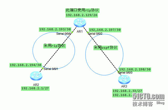
配置过程如下:
1、各路由器设备端口配置:
R1
R2
R3
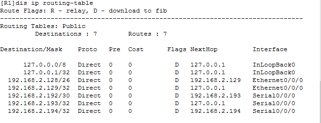
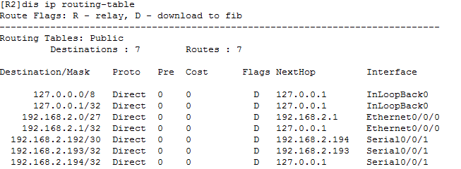
2、未配置任何协议前各路由器的路由表
R1
R2
R3
3、各路由器配置相关协议
R1
R2
R3
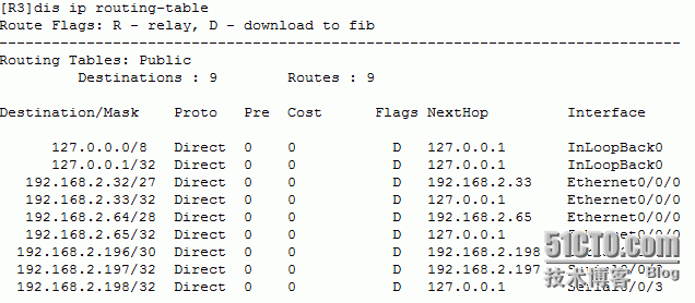
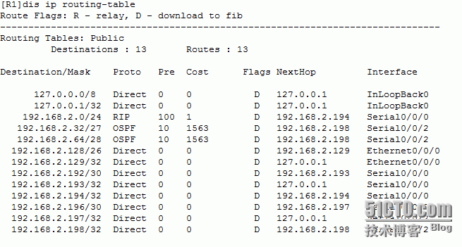
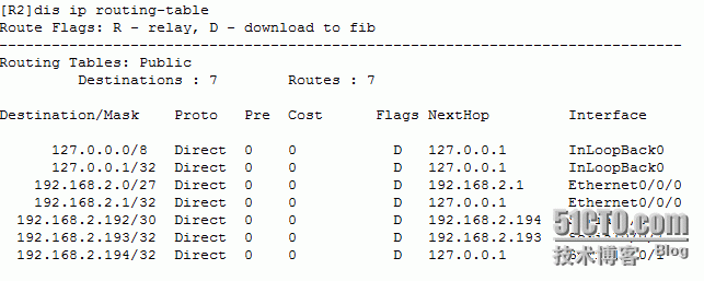
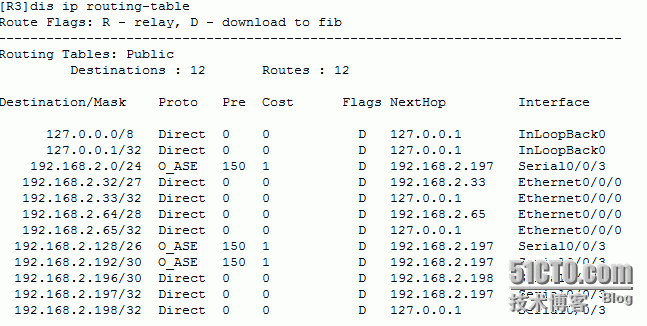
4、各路由器相关协议配置过后的路由表
R1
R2
R3
5、验证互通性:
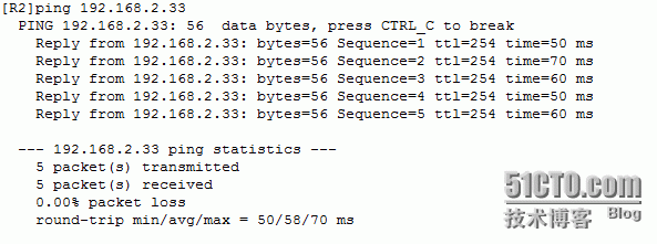
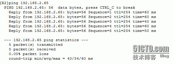
R2 ping R3
R3 ping R2
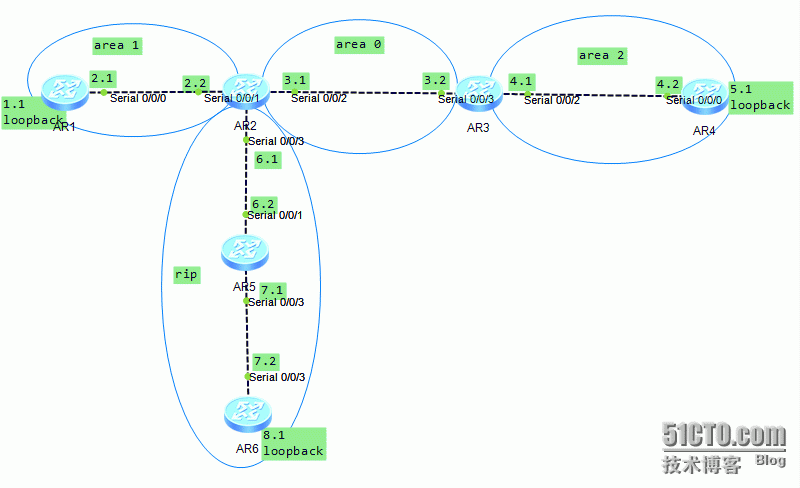
⑨rip协议与多区域ospf
拓扑图:
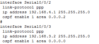
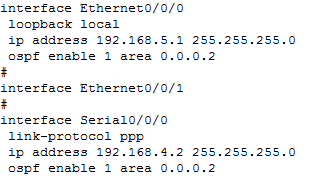
端口及协议配置结果:
R1
R2
R3
R4
R5
R6
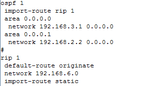
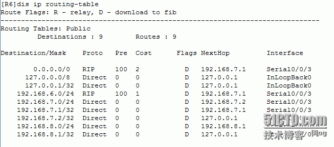
每个路由器都已经配置了相关的协议以及端口ip,下面需要在R2配置路由转发功能,使rip协议网络能够发送数据到ospf协议网络。由于已知rip协议网络为小型网络,故不能够将ospf网络数据路由转发给rip网络,需要在rip与ospf临界区域的路由器配置默认路由,能够解决ospf网络与rip网络基本的通信,但不会对rip网络区域的路由器造成堵塞或者压力。解决方法的配置过程如下:
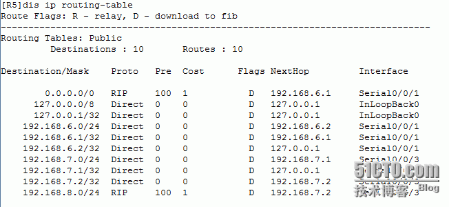
配置默认路由后的路由表:
R5
R6
验证实验结果:
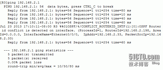
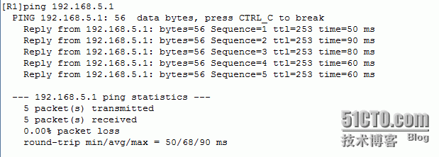
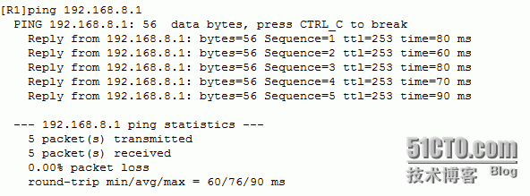
R1 ping R4
R1 ping R6
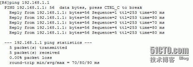
R6 ping R1
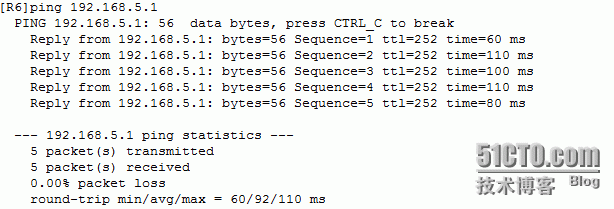
R6 ping R4
这些都是常用的ospf协议的应用案例。
转载于:https://blog.51cto.com/7392072/1260725













 1181
1181


 被折叠的 条评论
为什么被折叠?


