


http://zh.wikipedia.org/wiki/IEEE_802
IEEE 802
指IEEE标准中关于局域网和城域网的一系列标准。更确切的说,IEEE 802标准仅限定在传输可变大小数据包的网络。
其中最广泛使用的有以太网、令牌环、无线局域网等。这一系列标准中的每一个子标准都由委员会中的一个专门工作组负责。
IEEE 802中定义的服务和协议限定在OSI模型[OSI网络参考模型]的最低两层(即物理层和数据链路层)。
事实上,IEEE 802将OSI的数据链路层分为两个子层,
分别是逻辑链路控制(LLC, Logical Link Control)和介质访问控制(MAC, Media Access Control),如下所示:
- 数据链路层
- 逻辑链路控制子层
- 介质访问控制子层
- 物理层
- IEEE 802.1:高层局域网协议(Bridging (networking) and Network Management)
- IEEE 802.2:逻辑链路控制(Logical link control)
- IEEE 802.3:以太网(Ethernet)
- IEEE 802.4:令牌总线(Token bus)
- IEEE 802.5:令牌环(Token-Ring)
- IEEE 802.6:城域网(MAN, Metropolitan Area Network)
- IEEE 802.7:宽带TAG(Broadband LAN using Coaxial Cable)
- IEEE 802.8:光纤分布式数据接口(FDDI)
- IEEE 802.9:综合业务局域网(Integrated Services LAN)
- IEEE 802.10:局域网网络安全(Interoperable LAN Security)
- IEEE 802.11:无线局域网(Wireless LAN & Mesh)
- IEEE 802.12:需求优先级(Demand priority)
- IEEE 802.13:(未使用)
- IEEE 802.14:电缆调制解调器(Cable modems)
- IEEE 802.15:无线个人网(Wireless PAN)
- IEEE 802.15.1:无线个人网络(WPAN, Wireless Personal Area Network)
- IEEE 802.15.4:低速无线个人网络(LR-WPAN, Low Rate Wireless Personal Area Network)
- IEEE 802.16:宽带无线接入(Broadband Wireless Access)
- IEEE 802.17:弹性数据包环传输技术(Resilient packet ring)
- IEEE 802.18:无线电管制技术(Radio Regulatory TAG)
- IEEE 802.19:共存标签(Coexistence TAG)
- IEEE 802.20:移动宽带无线接入(Mobile Broadband Wireless Access)
- IEEE 802.21:媒介独立换手(Media Independent Handover)
- IEEE 802.22:无线区域网(Wireless Regional Area Network)
- IEEE 802.23:紧急服务工作组(Emergency Services Working Group),2010年3月新发布
以太网(Ethernet)
是一种计算机局域网组网技术。IEEE制定的IEEE 802.3标准给出了以太网的技术标准。
它规定了包括物理层的连线、电信号和介质访问层协议的内容。以太网是当前应用最普遍的局域网技术。
它很大程度上取代了其他局域网标准,如令牌环网(token ring)、FDDI和ARCNET。
以太网的标准拓扑结构为总线型拓扑,但目前的快速以太网(100BASE-T、1000BASE-T标准)为了最大程度的减少冲突,
最大程度的提高网络速度和使用效率,使用交换机(Switch hub)来进行网络连接和组织,这样,以太网的拓扑结构就成了星型,
但在逻辑上,以太网仍然使用总线型拓扑和CSMA/CD(Carrier Sense Multiple Access/Collision Detection
即带冲突检测的载波监听多路访问)的总线争用技术。
以太网基于网络上无线电系统多个节点发送信息的想法实现,每个节点必须取得电缆或者信道的才能传送信息,有时也叫作以太(Ether)。
(这个名字来源于19世纪的物理学家假设的电磁辐射媒体-光以太。后来的研究证明光以太不存在。)
每一个节点有全球唯一的48位地址也就是制造商分配给网卡的MAC地址,以保证以太网上所有系统能互相鉴别。
由于以太网十分普遍,许多制造商把以太网卡直接集成进计算机主板.
已经发现以太网通讯具有自相关性的特点,这对于电信通讯工程十分重要的。
带冲突检测的载波侦听多路访问(CSMA/CD)技术规定了多台电脑共享一个通道的方法。
这项技术最早出现在1960年代由夏威夷大学开发的ALOHAnet,它使用无线电波为载体。
这个方法要比令牌环网或者主控制网要简单。当某台电脑要发送信息时,必须遵守以下规则:
- 开始 - 如果线路空闲,则启动传输,否则转到第4步
- 发送 - 如果检测到冲突,继续发送数据直到达到最小报文时间
(保证所有其他转发器和终端检测到冲突),再转到第4步. - 成功传输 - 向更高层的网络协议报告发送成功,退出传输模式。
- 线路忙 - 等待,直到线路空闲
- 线路进入空闲状态 - 等待一个随机的时间,转到第1步,除非超过最大尝试次数
- 超过最大尝试传输次数 - 向更高层的网络协议报告发送失败,退出传输模式
就像在没有主持人的座谈会中,所有的参加者都通过一个共同的媒介(空气)来相互交谈。
每个参加者在讲话前,都礼貌地等待别人把话讲完。
如果两个客人同时开始讲话,那么他们都停下来,分别随机等待一段时间再开始讲话。
这时,如果两个参加者等待的时间不同,冲突就不会出现。
如果传输失败超过一次,将采用退避指数增长时间的方法
(退避的时间通过截断二进制指数退避算法(truncated binary exponential backoff)来实现)。
最初的以太网是采用同轴电缆来连接各个设备的。
电脑通过一个叫做附加单元接口(Attachment Unit Interface,AUI)的收发器连接到电缆上。
一根简单网线对于一个小型网络来说还是很可靠的,对于大型网络来说,
某处线路的故障或某个连接器的故障,都会造成以太网某个或多个网段的不稳定。
因为所有的通信信号都在共用线路上传输,即使信息只是发给其中的一个终端(destination),
某台电脑发送的消息都将被所有其他电脑接收。
在正常情况下,网络接口卡会滤掉不是发送给自己的信息,接收目标地址是自己的信息时才会向CPU发出中断请求,
除非网卡处于混杂模式(Promiscuous mode)。
这种“一个说,大家听”的特质是共享介质以太网在安全上的弱点,因为以太网上的一个节点可以选择是否监听线路上传输的所有信息。
共享电缆也意味着共享带宽,所以在某些情况下以太网的速度可能会非常慢,比如电源故障之后,当所有的网络终端都重新启动时。
在以太网技术的发展中,以太网集线器(Ethernet Hub)的出现使得网络更加可靠,接线更加方便。
因为信号的衰减和延时,根据不同的介质以太网段有距离限制。
例如,10BASE5同轴电缆最长距离500米 (1,640英尺)。最大距离可以通过以太网中继器实现,中继器可以把电缆中的信号放大再传送到下一段。
中继器最多连接5个网段,但是只能有4个设备(即一个网段最多可以接4个中继器)。
这可以减轻因为电缆断裂造成的问题:当一段同轴电缆断开,所有这个段上的设备就无法通讯,中继器可以保证其他网段正常工作。
早期的网桥要检测每一个数据包,这样,特别是同时处理多个端口的时候,数据转发相对Hub(中继器)来说要慢。
1989年网络公司Kalpana发明了EtherSwitch,第一台以太网交换机。
以太网交换机把桥接功能用硬件实现,这样就能保证转发数据速率达到线速。
大多数现代以太网用以太网交换机代替Hub。
尽管布线同Hub以太网是一样的,但是交换式以太网比共享介质以太网有很多明显的优势,例如更大的带宽和更好的结局隔离异常设备。
交换网络典型的使用星型拓扑,尽管设备工作在半双工模式是仍然是共享介质的多结点网。
10BASE-T和以后的标准是全双工以太网,不再是共享介质系统。
交换机加电后,首先也像Hub那样工作,转发所有数据到所有端口。
接下来,当它学习到每个端口的地址以后,他就只把非广播数据发送给特定的目的端口。
这样,线速以太网交换就可以在任何端口对之间实现,所有端口对之间的通讯互不干扰。
因为数据包一般只是发送到他的目的端口,所以交换式以太网上的流量要略微小于共享介质式以太网。
尽管如此,交换式以太网依然是不安全的网络技术,因为它还很容易因为ARP欺骗或者MAC满溢而瘫痪,
同时网络管理员也可以利用监控功能抓取网络数据包。
当只有简单设备(除Hub之外的设备)接入交换机端口,那么整个网络可能工作在全双工方式。
如果一个网段只有2个设备,那么冲突探测也不需要了,两个设备可以随时收发数据。
总的带宽就是链路的2倍(尽管带宽每个方向上是一样的),但是没有冲突发生就意味着允许几乎100%的使用链路带宽。
交换机端口和所连接的设备必须使用相同的双工设置。
多数100BASE-TX和1000BASE-T设备支持自动协商特性,即这些设备通过信号来协调要使用的速率和双工设置。
然而,如果自动协商被禁用或者设备不支持,则双工设置必须通过自动检测进行设置
或在交换机端口和设备上都进行手工设置以避免双工错配——这是以太网问题的一种常见原因
(设备被设置为半双工会报告迟发冲突,而设备被设为全双工则会报告runt)。
许多低端交换机没有手工进行速率和双工设置的能力,因此端口总是会尝试进行自动协商。
当启用了自动协商但不成功时(例如其他设备不支持),自动协商会将端口设置为半双工。
速率是可以自动感测的,因此将一个10BASE-T设备连接到一个启用了自动协商的10/100交换端口上时
将可以成功地创建一个半双工的10BASE-T连接。
但是将一个配置为全双工100Mb工作的设备连接到一个配置为自动协商的交换端口时(反之亦然)则会导致双工错配。
即使电缆两端都设置成自动速率和双工模式协商,错误猜测还是经常发生而退到10Mbps模式。
因此,如果性能差于预期,应该查看一下是否有计算机设置成10Mbps模式了,如果已知另一端配置为100Mbit,则可以手动强制设置成正确模式。.
当两个节点试图用超过电缆最高支持数据速率(例如在3类线上使用100Mbps或者3类/5类线使用1000Mbps)通信时就会发生问题。
不像ADSL或者传统的拨号Modem通过详细的方法检测链路的最高支持数据速率,
以太网节点只是简单的选择两端支持的最高速率而不管中间线路。
因此如果过高的速率导致电缆不可靠就会导致链路失效。解决方案只有强制通讯端降低到电缆支持的速率。
IEEE 802.11
IEEE 802.11是现今无线局域网通用的标准,它是由国际电机电子工程学会(IEEE)所定义的无线网络通信的标准。
虽然有人将Wi-Fi与802.11混为一谈,但两者并不一样。(见IEEE 802.11b)
IEEE 802.11b是无线局域网的一个标准。其载波的频率为2.4GHz,可提供1、2、5.5及11Mbit/s的多重传送速度[1]。
它有时也被错误地标为Wi-Fi。实际上Wi-Fi是Wi-Fi联盟的一个商标,该商标仅保障使用该商标的商品互相之间可以合作,
与标准本身实际上没有关系。[来源请求]在2.4-GHz的ISM频段共有11个频宽为22MHz的频道可供使用,
它是11个相互重叠的频段。IEEE 802.11b的后继标准是IEEE 802.11g。
Ethernet Frame Formats
http://www.wildpackets.com/resources/compendium/ethernet/frame_formats
An understanding of the basics of the Ethernet Frame Format is crucial to any discussion of Ethernet technology.
In this document, we will discuss:
- The four different frame formats used in the Ethernet world
- The purpose of each of the fields in an Ethernet frame.
- The reasons that there are so many different versions of the Ethernet Frame Format
The Different "Flavors" of Ethernet
While the preamble is common to every type of Ethernet, what follows it is certainly not. The major types of Ethernet Frame Format are:
| Frame Type | Novel calls it... | Cisco calls it... |
| IEEE 802.3 | ETHERNET_802.2 | LLC |
| Version II | ETHERNET_II | ARPA |
| IEEE 802.3 | SNAP | ETHERNET_SNAP SNAP |
| Novell Proprietary ("802.3 Raw") | ETHERNET_802.3 | NOVELL |
Frame Formats - Ethernet IEEE 802.3
The following is a description of the Ethernet Frame Format described in the IEEE 802.3 Specification.
The 802.3 Specification defines a 14 byte Data Link Header followed
by a Logical Link Control Header that is defined by the 802.2 Specification.

The Data Link Header
Offset 0-5: The Destination Address
The first six bytes of an Ethernet frame make up the Destination Address.
The Destination Address specifies to which adapter the data frame is being sent.
A Destination Address of all ones specifies a Broadcast Message that is read in by all receiving Ethernet adapters.
The first three bytes of the Destination Address are assigned by the IEEE to the vendor of the adapter,
and are specific to the vendor.
The Destination Address format is identical in all implementations of Ethernet.
Offset 6-11: The Source Address
The next six bytes of an Ethernet frame make up the Source Address.
The Source Address specifies from which adapter the message originated.
Like the Destination Address, the first three bytes specify the vendor of the card.
The Source Address format is identical in all implementations of Ethernet.
Offset 12-13: Length
Bytes 13 and 14 of an Ethernet frame contain the length of the data in the frame,
not including the preamble, 32 bit CRC, DLC addresses, or the Length field itself.
An Ethernet frame can be no shorter than 64 bytes total length,
and no longer than 1518 bytes total length.
THE 802.2 LOGICAL LINK CONTROL (LLC) HEADER
Following the Data Link Header is the Logical Link Control Header, which is described in the IEEE 802.2 Specification.
The purpose of the LLC header is to provide a "hole in the ceiling" of the Data Link Layer.
By specifying into which memory buffer the adapter places the data frame,
the LLC header allows the upper layers to know where to find the data.
Offset 15: The DSAP
The DSAP, or Destination Service Access Point, is a 1 byte field that simply acts
as a pointer to a memory buffer in the receiving station.
It tells the receiving NIC in which buffer to put this information.
This functionality is crucial in situations where users are running multiple protocol stacks, etc...
Offset 16: The SSAP
The SSAP, or Source Service Access Point is analogous to the DSAP,
and specifies the Source of the sending process.
Offset 17: The Control Byte
Following the SAPs is a one byte control field that specifies the type of LLC frame that this is.
USER DATA AND THE FRAME CHECK SEQUENCE (FCS)
Data: 43-1497 Bytes
Following the 802.2 header are 43 to 1,497 bytes of data,
generally consisting of upper layer headers such as TCP/IP or IPX and then the actual user data.
FCS: Last 4 Bytes
The last 4 bytes that the adapter reads in are the Frame Check Sequence or CRC.
When the voltage on the wire returns to zero, the adapter checks the last 4 bytes it received against a checksum
that it generates via a complex polynomial. If the calculated checksum does not match the checksum on the frame,
the frame is discarded and never reaches the memory buffers in the station.
Frame Formats - Version II
The following is a description of the frame format described by the original Ethernet Version II specification,
as released by DEC, Intel, and Xerox.
Like the 802.3 spec, the Version II spec defines a Data Link Header consisting of 14 bytes of information,
but the Version II spec does not specify an LLC header.
The Data Link Header
Offset 0-5: The Destination Address
The first six bytes of an Ethernet frame make up the Destination Address.
The Destination Address specifies to which adapter the data frame is being sent.
A Destination Address of all ones specifies a Broadcast Message that is read in by all receiving Ethernet adapters.
The first three bytes of the Destination Address are assigned by the IEEE to the vendor of the adapter, and are specific to the vendor.
The Destination Address format is identical in all implementations of Ethernet.
Offset 6-11: The Source Address
The next six bytes of an Ethernet frame make up the Source Address.
The Source Address specifies from which adapter the message originated.
Like the Destination Address, the first three bytes specify the vendor of the card.
The Source Address format is identical in all implementations of Ethernet.
Offset 12-13: The Ethertype
Following the Source Address is a 2 byte field called the Ethertype.
The Ethertype is analogous to the SAPs in the 802.3 frame
in that it specifies the memory buffer in which to place this frame.
An interesting question arises when one considers the 802.3 and Version II frame formats:
Both formats specify a 2 byte field following the source address (an Ethertype in Version II, and a Length field in 802.3)
-- How does a driver know which format it is seeing, if it is configured to support both?
The answer is actually quite simple. All Ethertypes have a value greater than 05DC hex, or 1500 decimal.
Since the maximum frame size in Ethernet is 1518 bytes, there is no point of overlap between Ethertypes and lengths.
6 + 6 + 2 + 1 + 1 + 1 + (43 .. 1497 ) + 4 = ( 64 .. 1518 ) [ Length = 43 .. 1497 = 0x002B .. 0x05D9 ]
If the field that follows the Source Address is greater than 0x05DC , the frame is a Version II,
otherwise, it is something else (either 802.3, 802.3 SNAP, or Novell Proprietary).
User Data and FCS
Data: 46-1500 Bytes
Following the Ethertype are 46 to 1,500 bytes of data, generally consisting of upper layer headers
such as TCP/IP or IPX and then the actual user data.
FCS: Last 4 Bytes
The last 4 bytes that the adapter reads in are the Frame Check Sequence or CRC.
When the voltage on the wire returns to zero, the adapter checks the last 4 bytes it received against a checksum
that it generates via a complex polynomial. If the calculated checksum does not match the checksum on the frame,
the frame is discarded and never reaches the memory buffers in the station.
6 + 6 + 2 + (46 .. 1500) + 4 = ( 64 .. 1518 )
虽然以太网和IEEE 802.3在很多方面都非常相似,但是两种规范之间仍然存在着一定的区别。
以太网所提供的服务主要对应于OSI参考模型的第一和第二层,即物理层和逻辑链路层;而
IEEE 802.3则主要是对物理层和逻辑链路层的通道访问部分进行了规定。
此外,IEEE 802.3没有定义任何逻辑链路控制协议,但是指定了多种不同的物理层,而以太网只提供了一种物理层协议。
以太网/IEEE 802.3帧的基本组成
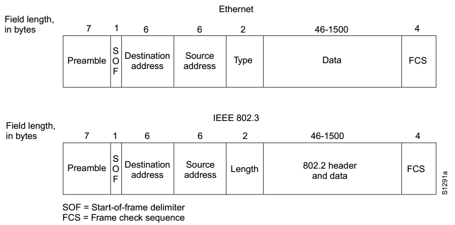

以太网和IEEE 802.3帧的基本结构如下:
前导码:由0、1间隔代码组成,可以通知目标站作好接收准备。
IEEE 802.3帧的前导码占用7个字节,紧随其后的是长度为1个字节的帧首定界符(SOF)。
以太网帧把SOF包含在了前导码当中,因此,前导码的长度扩大为8个字节。
帧首定界符(SOF):IEEE 802.3帧中的定界字节,以两个连续的代码1结尾,表示一帧实际开始。
目标和源地址:表示发送和接收帧的工作站的地址,各占据6个字节。
其中,目标地址可以是单址,也可以是多点传送或广播地址。
类型(以太网):占用2个字节,指定接收数据的高层协议。
长度(IEEE 802.3):表示紧随其后的以字节为单位的数据段的长度。
数据(以太网):在经过物理层和逻辑链路层的处理之后,包含在帧中的数据将被传递给在类型段中指定的高层协议。
虽然以太网版本2中并没有明确作出补齐规定,但是以太网帧中数据段的长度最小应当不低于46个字节。
数据(IEEE 802.3):IEEE 802.3帧在数据段中对接收数据的上层协议进行规定。
如果数据段长度过小,使帧的总长度无法达到64个字节的最小值,
那么相应软件将会自动填充数据段,以确保整个帧的长度不低于64个字节。
帧校验序列(FSC):该序列包含长度为4个字节的循环冗余校验值(CRC),
由发送设备计算产生,在接收方被重新计算以确定帧在传送过程中是否被损坏。
Frame Formats - Snap IEEE 802.3
While the original 802.3 specification worked well, the IEEE realized
that some upper layer protocols required an Ethertype to work properly.
For example, TCP/IP uses the Ethertype to differentiate between ARP packets and normal IP data frames.
In order to provide this backwards compatibility with the Version II frame type,
the 802.3 SNAP (SubNetwork Access Protocol) format was created.
The SNAP Frame Format consists of a normal 802.3 Data Link Header followed
by a normal 802.2 LLC Header, and then a 5 byte SNAP field,
followed by the normal user data and FCS.
The Data Link Header
Offset 0-5: The Destination Address
The first six bytes of an Ethernet frame make up the Destination Address.
The Destination Address specifies to which adapter the data frame is being sent.
A Destination Address of all ones specifies a Broadcast Message that is read in by all receiving Ethernet adapters.
The first three bytes of the Destination Address are assigned by the IEEE to the vendor of the adapter, and are specific to the vendor.
The Destination Address format is identical in all implementations of Ethernet.
Offset 6-11: The Source Address
The next six bytes of an Ethernet frame make up the Source Address.
The Source Address specifies from which adapter the message originated.
Like the Destination Address, the first three bytes specify the vendor of the card.
The Source Address format is identical in all implementations of Ethernet.
Offset 12-13: Length
Bytes 13 and 14 of an Ethernet frame contain the length of the data in the frame,
not including the preamble, 32 bit CRC, DLC Addresses, or the Length field itself.
An Ethernet frame can be no shorter than 64 bytes, and no longer than 1518 bytes in total length.
The 802.2 Logical Link Control Header (LLC)
Following the Data Link Header is the Logical Link Control Header, which is described in the IEEE 802.2 Specification.
The purpose of the LLC header is to provide a "hole in the ceiling" of the Data Link Layer.
By specifying into which memory buffer the adapter places the data frame,
the LLC header allows the upper layers to know where to find the data.
Offset 14: The DSAP
The DSAP, or Destination Service Access Point, is a 1 byte field that simply acts as a pointer
to a memory buffer in the receiving station.
It tells the receiving NIC in which buffer to put this information.
This functionality is crucial in situations where users are running multiple protocol stacks, etc...
In order to specify that this is a SNAP frame, the DSAP is set to AA hex.
Offset 15: The SSAP
The SSAP, or Source Service Access Point is analogous to the DSAP,
and specifies the Service Access Point (SAP) of the sending process.
In order to specify that this is a SNAP frame, the SSAP is set to AA hex.
Offset 16: The Control Byte
Following the SAPs is a one byte control field that specifies the type of LLC frame that this is.
The Sub-Network Access Protocol (SNAP) Header
Offset 17-19: The Vendor Code
The first 3 bytes of the SNAP header is the vendor code,
generally the same as the first three bytes of the source address, although it is sometimes set to zero.
Offset 20-21: The Local Code
Following the Vendor Code is a 2 byte field that typically contains an Ethertype for the frame.
Here is where the backwards compatibility with Version II Ethernet is implemented.
User Data and the Frame Check Sequence (FCS)
Data: 38-1492 Bytes
Following the 802.2 header are 38 to 1,492 bytes of data, generally consisting of upper layer headers
such as TCP/IP or IPX and then the actual user data.
FCS: Last 4 Bytes
The last 4 bytes that the adapter reads in are the Frame Check Sequence or CRC.
When the voltage on the wire returns to zero, the adapter checks the last 4 bytes
it received against a checksum that it generates via a complex polynomial.
If the calculated checksum does not match the checksum on the frame, the frame is discarded
and never reaches the memory buffers in the station.
Frame Formats - Novell Proprietary
Novell's Proprietary Frame Format was developed based on a preliminary release of the 802.3 specification.
After Novell released their proprietary format, the LLC Header was added, making Novell's format incompatible.
The Data Link Header
Offset 0-5: The Destination Address
The first six bytes of an Ethernet frame make up the Destination Address.
The Destination Address specifies to which adapter the data frame is being sent.
A Destination Address of all ones specifies a Broadcast Message that is read in by all receiving Ethernet adapters.
The first three bytes of the Destination Address are assigned by the IEEE to the vendor of the adapter,
and are specific to the vendor.
The Destination Address format is identical in all implementations of Ethernet.
Offset 6-11: The Source Address
The next six bytes of an Ethernet frame make up the Source Address.
The Source Address specifies from which adapter the message originated.
Like the Destination Address, the first three bytes specify the vendor of the card.
The Source Address format is identical in all implementations of Ethernet.
Offset 12-13: Length
Bits 13 and 14 of an Ethernet frame contain the length of the entire data frame,
not including the preamble or 32 bit CRC.
An Ethernet frame can be no shorter than 64 bytes, and no longer than 1518 bytes.
User Data and the Frame Check Sequence (FCS)
Data: 46-1497 Bytes
Following the Data Link header are 46 to 1500 bytes of data.
In all Novell frames, the user data begins with an IPX (Novell's network layer protocol) header.
The IPX header contains as its first two bytes an optional checksum,
with the value FFFF signifying that the checksum is not used.
By convention, the checksum is always turned off, and the FFFF that occurs 3 bytes
after the end of the source address is how device drivers differentiate Novell frames from 802.3 frames,
which look identical until the first byte following the length field.
FCS: Last 4 Bytes
The last 4 bytes that the adapter reads in are the Frame Check Sequence or CRC.
When the voltage on the wire returns to zero, the adapter checks the last 4 bytes
it received against a checksum that it generates via a complex polynomial.
If the calculated checksum does not match the checksum on the frame,
the frame is discarded and never reaches the memory buffers in the station.
A Final Note on the Novell Ethernet Frame Format
"A Novell client can only use one frame format for NetWare"
This is a true statement that needs some clarification to be fully understood.
It should be noted that Novell workstations are capable of
using any of the four Ethernet frame types mentioned in this essay,
based on the LOAD and BIND settings in the NET.CFG file.
A Novell client will use the list of frame formats in NET.CFG to attempt
to locate a file server (or a Netware Directory Server for the VLM shell).
The client starts at the top of the list of frame types in NET.CFG
and broadcasts a 'Find Nearest Server' message.
If no file server answers (or Directory Services server in a VLM client) then
the client tries the next frame format.
When a server finally does answer then the client
will use the successful frame format from then on; until the client is rebooted.
As a result, you should remember that a Novell client will ultimately use only one of the four frame formats;
it can not actually use multiple formats for NetWare at the same time.
The format it selects will be based on its initial attempt to locate a server.
This behavior is restricted to the frame format used by NCP and SPX -
if the client is also running a TCP/IP stack then the IP protocol can be configured
to use any other frame format (typically Version II Ethernet).
Ethernet帧和802.3帧区别
http://jh391546079.blog.51cto.com/2417107/898267
首先说明一下,Ethernet和802.3并不是一回事,虽然我们经常混用这两个术语;
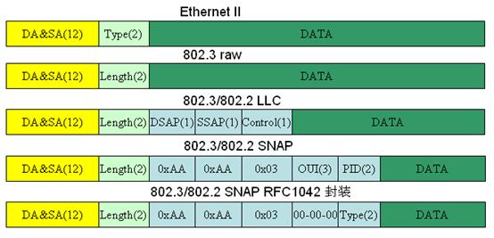
历史上以太网帧格式有五种:
1.Ethernet V1:这是最原始的一种格式,是由Xerox PARC提出的3Mbps CSMA/CD以太网标准的封装格式,
后来在1980年由DEC,Intel和Xerox标准化形成Ethernet V1标准;
2.Ethernet V2(ARPA):
这是最常见的一种以太网帧格式,也是今天以太网的事实标准,由DEC,Intel和Xerox在1982年公布其标准,主要
更改了Ethernet V1的电气特性和物理接口,在帧格式上并无变化;
Ethernet V2出现后迅速取代Ethernet V1成为以太网事实标准;
Ethernet V2帧头结构为6bytes的源地址+6bytes的目标地址+2Bytes的协议类型字段+数据。
常见协议类型如下:
0800 IP
0806 ARP
8137 Novell IPX
809b Apple Talk
如果协议类型字段取值为0000-05dc(十进制的0-1500),则该帧就不是Ethernet V2(ARPA)类型了,
而是下面讲到的三种802.3帧类型之一;Ethernet可以支持TCP/IP,Novell IPX/SPX,Apple Talk Phase I等协议;
RFC 894定义了IP报文在Ethernet V2上的封装格式;
3.RAW 802.3:
这是1983年Novell发布其划时代的Netware/86网络套件时采用的私有以太网帧格式,该格式以当时尚未正式发布的802.3标准为基础;
但是当两年以后IEEE正式发布802.3标准时情况发生了变化—IEEE在802.3帧头中又加入了802.2 LLC(Logical Link Control)头,
这使得Novell的RAW 802.3格式跟正式的IEEE 802.3标准互不兼容;可以看到在Novell的RAW 802.3帧结构中并没有标志协议类型的字段,
而只有Length 字段(2bytes,取值为0000-05dc,即十进制的0-1500),因为RAW 802.3帧只支持IPX/SPX一种协议;
4.802.3/802.2 LLC:这是IEEE 正式的802.3标准,它由Ethernet V2发展而来。
它将Ethernet V2帧头的协议类型字段替换为帧长度字段(取值为0000-05dc;十进制的1500 );
并加入802.2 LLC头用以标志上层协议,LLC头中包含DSAP,SSAP以及Crontrol字段;
常见SAP值:
0:Null LSAP[IEEE]
4:SNA Path Control[IEEE]
6:DOD IP[79,JBP]
AA:SNAP[IEEE]
FE:ISO DIS 8473[52,JXJ]
FF:Global DSAP[IEEE]
SAP 值用以标志上层应用,但是每个SAP字段只有8bits长,而且其中仅保留了6比特用于标识上层协议,因此所能标识的协议数有限(不超过32种);
并且 IEEE拒绝为某些重要的协议比如ARP协议定义SAP值(奇怪的是同时他们却定义了IP 的SAP值);因此802.3/802.2 LLC的使用有很大局限性;
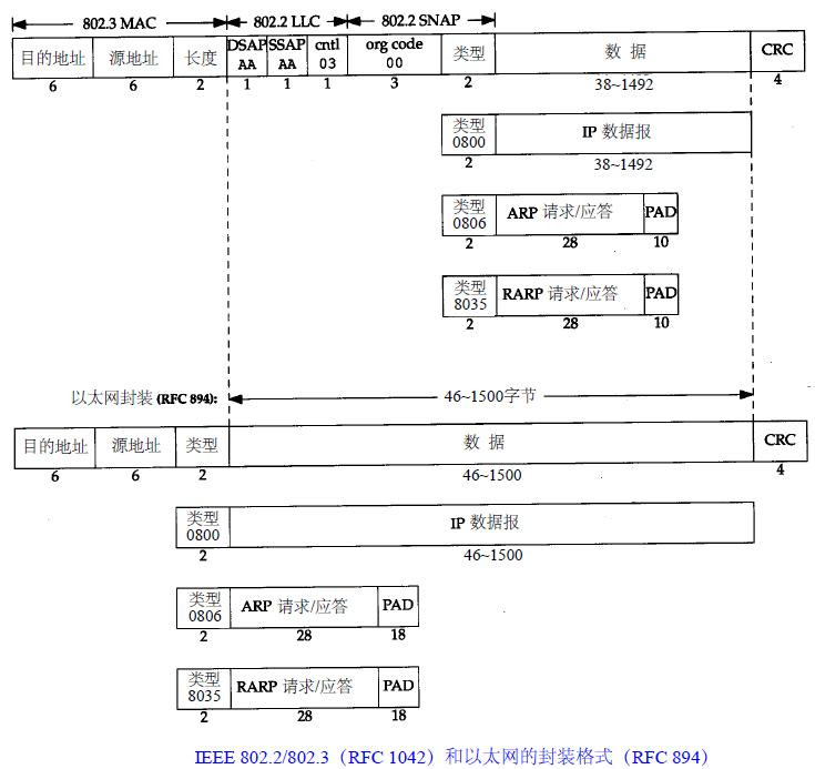
5.802.3/802.2 SNAP:这是IEEE为保证在 802.2 LLC上支持更多的上层协议同时更好的支持IP协议而发布的标准,
与802.3/802.2 LLC一样802.3/802.2 SNAP也带有LLC头,但是扩展了LLC属性,新添加了一个2Bytes的协议类型域(同时将SAP的值置为AA),
从而使其可以标识更多的上层协议类型;另外添加了一个3Bytes的OUI字段用于代表不同的组织,
RFC 1042定义了IP报文在802.2网络中的封装方法和ARP协议在802.2 SANP中的实现;
今天的实际环境中大多数 TCP/IP设备都使用Ethernet V2格式的帧。
这是因为第一种大规模使用的TCP/IP系统(4.2/3 BSD UNIX)的出现时间介于RFC 894和RFC 1042之间,
它为了避免不能和别的主机互操作的风险而采用了RFC 894的实现;也由于大家都抱着这种想法,所以802. 3标准并没有如预期那样得到普及;
CISCO设备的Ethernet Interface默认封装格式是ARPA(Ethernet V2)
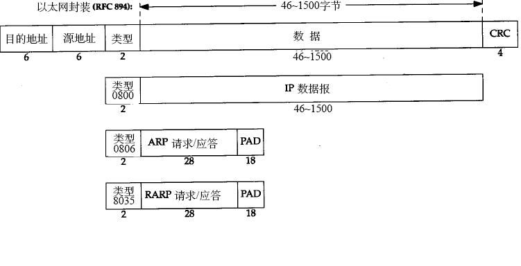
以太网协议封装格式
http://blog.csdn.net/kevin_tang0926/article/details/7432584
一、以太网链路层协议封装格式
以太网数据在网络介质上传输需要遵循一定的机制,其中CSMA/CD介质访问控制机制约定了以太网在传输数据时,
两帧之间需要等待一个帧间隙时间(IFG或IPG),为以太网接口提供了帧接收之间的恢复时间,
该恢复时间最小值为传输96bit所花费的时间,对于10M线路,该时间为9.6uS,100M线路为960nS,1G的线路为96nS。
同时以太网数据帧在传输时还需要有7byte的前导字段和1byte的定界符。
因此以太网数据在传输过程中是由以下部分组成的:7byte(前导)+1byte(定界符)+以太网数据帧+12byte(IPG)。
在全双工工作模式下,如果CSMA/CD介质访问控制机制发现传输冲突时,则会放弃当前帧发送,改为发送一个48比特的噪声帧。
其中以太网数据帧限制为最小长度为64byte,最大长度为1518byte,其格式为:
6byte(目的MAC地址)+6byte(源MAC地址)+2byte(类型字段)+数据字段+4byte(FCS校验字段)。
其中帧类型字段标识其后的数据类型。这里值得注意的是区分Ethernet II帧格式和802.3帧格式的不同,我们有时可能会混用了这两个术语。
Ethernet II帧是最常见的一种以太网帧格式,也是今天以太网的事实标准,由DEC,Intel和Xerox在1982年公布标准,
Ethernet II可以支持TCP/IP,Novell IPX/SPX,Apple Talk Phase I等协议,
其比较常见的类型字段为:0X0800(IP帧),0X0806(ARP请求/应答帧),0X8035(PARP请求/应答帧),
0X8137(Novell IPX),0X809b(Apple Talk)。RFC 894定义了IP报文在Ethernet II上的封装格式。
802.3帧将Ethernet II帧头中的类型字段替换为帧长度字段(取值范围为0X0000-0X05dc,不包括CRC检验码),
因此对于接收到的帧,如果类型字段取值范围为0X0000-0X05dc,则可以判断其为802.3帧,而非Ethernet II帧。
其中RAW 802.3是1983年Novell发布Netware/86网络套件时采用的私有以太网帧格式,只支持IPX/SPX一种协议;
802.3/802.2 LLC是IEEE 公布的正式802.3标准,它加入了3byte的LLC字段,
其中SAP值用以标志上层应用,每个SAP字段为8bits,其中只有6bit用于标识上层协议,
因此所能标识的协议数不超过32种,导致802.3/802.2 LLC的使用有很大局限性;
802.3/802.2 SNAP是IEEE为保证在802.2 LLC上支持更多的上层协议同时更好的支持IP协议而发布的标准,
在802.3/802.2 LLC基础上添加了5byte的SNAP字段,从而使其可以标识更多的上层协议类型,
OUI字段用于代表不同的组织(一般置为0),在802.3/802.2 SNAP基础上RFC1042定义了IP报文在802.2网络中的封装方法和ARP协议在802.2 SANP中的实现。
目前实际环境中大多数TCP/IP设备都使用Ethernet II格式的帧,它采用了RFC 894的实现标准。
从上述帧格式中可以看出,Ethernet II格式帧数据段的长度限制在46byte-1500byte之间,
当数据段长度小于46个字节时,加填充字段(PAD)补足。
Ethernet II和802.3对数据帧的长度限制,其最大值分别是1500和1492字节,这一特性称作最大传输单元(MTU)。
如果IP层有一个数据报要传,而且数据的长度比链路层的MTU还大,那么IP层就要进行分片(Fragmentation),
把数据报分成若干片,这样每一片都小于MTU。当网络上的两台主机互相进行通信时,两台主机之间要经过多个网络,
每个网络的链路层可能有不同的MTU,其中两台通信主机路径中的最小MTU被称作路径MTU,
Internet上标准MTU为576B(TCP)、512B(UDP)。
在TCP/IP协议族中,链路层主要有三个目的:
(1)为IP模块发送和接收IP数据报;
(2)为ARP模块发送ARP请求和接收ARP应答;
(3)为RARP发送RARP请求和接收RARP应答。
在TCP/IP协议族中基于链路层以上的协议主要有三种:IP协议、ARP协议和RARP协议,
其中在IP数据报中又额外封装了ICMP协议和IGMP协议。
IP层协议也就是通常的网络层协议,它提供点到点的服务(不同于传输层TCP/UDP协议提供端到端的服务)。
其中的源地址和目的地址是指网卡的硬件地址(也叫MAC地址),长度是48位,是在网卡出厂时固化的。
用ifconfig命令看一下,“HWaddr 00:15:F2:14:9E:3F”部分就是硬件地址。
协议字段有三种值,分别对应IP、ARP、RARP。帧末尾是CRC校验码。
以太网帧中的数据长度规定最小46字节,最大1500字节,ARP和RARP数据包的长度不够46字节,要在后面补填充位。
ifconfig命令的输出中也有“MTU:1500”。注意,MTU这个概念指数据帧中有效载荷的最大长度,不包括帧首部的长度。
http://blog.csdn.net/jnu_simba/article/details/8962251
ARP(address resolution protocol)
在网络通讯时,源主机的应用程序知道目的主机的IP地址和端口号,却不知道目的主机的硬件地址,
而数据包首先是被网卡接收到再去处理上层协议的,如果接收到的数据包的硬件地址与本机不符,则直接丢弃。
因此在通讯前必须获得目的主机的硬件地址。ARP协议就起到这个作用。源主机发出ARP请求,
询问“IP地址是10.0.0.1的主机的硬件地址是多少”,并将这个请求广播到本地网段
(以太网帧首部的硬件地址填FF:FF:FF:FF:FF:FF表示广播),目的主机接收到广播的ARP请求,
发现其中的IP地址与本机相符,则发送一个ARP应答数据包给源主机,将自己的硬件地址填写在应答包中。如下图所示

每台主机都维护一个ARP缓存表,可以用arp -a命令查看。缓存表中的表项有过期时间(一般为20分钟),
如果20分钟内没有再次使用某个表项,则该表项失效,下次还要发ARP请求来获得目的主机的硬件地址。

注意到源MAC地址、目的MAC地址在以太网首部和ARP请求中各出现一次,
对于链路层为以太网的情况是多余的,但如果链路层是其它类型的网络则有可能是必要的。
硬件类型指链路层网络类型,1为以太网,协议类型指要转换的地址类型,0x0800为IP地址,
后面两个地址长度对于以太网地址和IP地址分别为6和4(字节),
op字段为1表示ARP请求,op字段为2表示ARP应答。
地址解析协议的处理流程如下图:

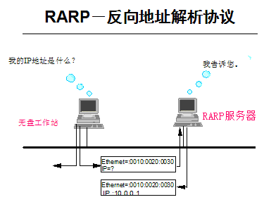
RARP(Reverse Address Resolution Protocol)
跟ARP相反的协议,主要用于获取无盘工作站的ip地址,如下图所示,不再赘述。
ICMP(Internet Control Message Protocol)
ICMP协议用于传递差错信息、时间、回显、网络信息等控制数据,如下图所示。

利用ARP和ICMP协议解释ping程序
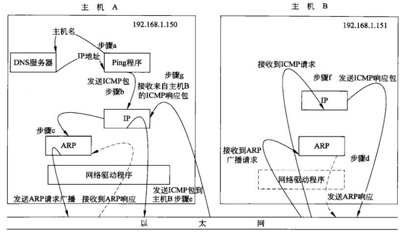
步骤a:应用程序ping会判断发送的是主机名还是IP地址,如果是主机名会调用函数
gethostbyname()解析主机B,将主机名转换成一个32位的IP地址。这个过程叫做DNS域名解析。
步骤b:ping程序向目的IP地址发送一个ICMP的ECHO包
步骤c:将目标主机的IP地址转换为48位硬件地址,在局域网内发送ARP请求广播,查找主机B的硬件地址。
步骤d:主机B的ARP协议层接收到主机A的ARP请求后,将本机的硬件地址填充到应答包,发送ARP应答到主机A。
步骤e:发送ICMP数据包到主机B。
步骤f:主机B接收到主机A的ICMP包,发送响应包。
步骤g:主机A接收到主机B的ICMP包响应包。


 1万+
1万+


 被折叠的 条评论
为什么被折叠?
被折叠的 条评论
为什么被折叠?
 到【灌水乐园】发言


