


 本文围绕基于Multicast实现的VxLAN展开,介绍其与基于Static Ingress Replication实现VxLAN的差异,阐述了实验环境、拓扑、配置、验证及报文分析过程,还提及集中式网关配置,最后总结两种实现方式的优缺点。
一、说明
- 与上一篇"1 实验1:基于静态Ingress Replication实现Cisco VxLAN & 集中式网关"相同,基于Multicast实现VxLAN也是流量驱动式的MAC地址泛洪学习和VTEP邻居建立,没有控制层面;
- 与基于Static Ingress Replication实现VxLAN不同,基于Multicast实现VxLAN无需手动为每个VNI配置peer;
- 当有流量触发即数据驱动时,VTEP之间的隧道才会自动建立;
- 与利用Static Ingress Replication实现BUM(广播、未知单播、组播)流量转发不同,基于Multicast实现BUM流量的转发可有效节省VTEP上行链路的带宽(具体参考组播网络特性)。
二、基于Multicast实现的VxLAN实验
2.1 实验环境
| 工具 | 版本 | 备注 |
|---|---|---|
| EVE-NG | 2.0.3-105 | 模拟器 |
| Cisco Nexus 9000v | 7.0.3.I7.8 | 支持VxLAN的交换机,拓扑中的N9K1、N9K-2、N9K-3和N9K-4 |
| Wireshark | 3.2.2 | 抓包软件 |
2.2 实验拓扑
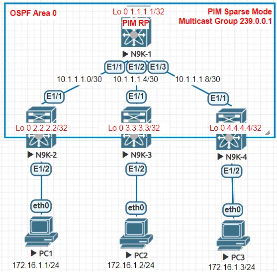
image.png
- N9K1、N9K-2、N9K-3和N9K-4运行OSPF协议;
- N9K1、N9K-2、N9K-3和N9K-4运行PIM Sparse Mode,其中PIM RP为1.1.1.1;
- 实现PC1、PC2和PC3能互通。
2.3 实验配置
2.3.1 配置Underlay三层网络
- 设备的互联接口、Loopback接口都通告进OSPF Area 0。
N9K-1配置:
feature ospf
router ospf n9k-1
  router-id 1.1.1.1

interface Ethernet1/1
  no switchport
  mtu 9216
  ip address 10.1.1.1/30
  ip ospf network point-to-point
  ip router ospf n9k-1 area 0.0.0.0
  no shutdown

interface Ethernet1/2
  no switchport
  mtu 9216
  ip address 10.1.1.5/30
  ip ospf network point-to-point
  ip router ospf n9k-1 area 0.0.0.0
  no shutdown

interface Ethernet1/3
  no switchport
  mtu 9216
  ip address 10.1.1.9/30
  ip ospf network point-to-point
  ip router ospf n9k-1 area 0.0.0.0
  no shutdown

interface loopback0
  ip address 1.1.1.1/32
  ip router ospf n9k-1 area 0.0.0.0
N9K-2配置:
vlan 10
feature ospf
router ospf n9k-2
  router-id 2.2.2.2

interface Ethernet1/1
  no switchport
  mtu 9216
  ip address 10.1.1.2/30
  ip ospf network point-to-point
  ip router ospf n9k-2 area 0.0.0.0
  no shutdown

interface loopback0
  ip address 2.2.2.2/32
  ip router ospf n9k-2 area 0.0.0.0

interface Ethernet1/2
  switchport access vlan 10
  spanning-tree port type edge
N9K-3配置:
vlan 10
feature ospf
router ospf n9k-3
  router-id 3.3.3.3

interface Ethernet1/1
  no switchport
  mtu 9216
  ip address 10.1.1.6/30
  ip ospf network point-to-point
  ip router ospf n9k-3 area 0.0.0.0
  no shutdown

interface loopback0
  ip address 3.3.3.3/32
  ip router ospf n9k-3 area 0.0.0.0

interface Ethernet1/2
  switchport access vlan 10
  spanning-tree port type edge
N9K-4配置:
vlan 10
feature ospf
router ospf n9k-4
  router-id 4.4.4.4

interface Ethernet1/1
  no switchport
  mtu 9216
  ip address 10.1.1.10/30
  ip ospf network point-to-point
  ip router ospf n9k-4 area 0.0.0.0
  no shutdown

interface loopback0
  ip address 4.4.4.4/32
  ip router ospf n9k-4 area 0.0.0.0

interface Ethernet1/2
  switchport access vlan 10
  spanning-tree port type edge
配置验证:
查看N9K-1 OSPF路由表:
N9K-1# show  ip route ospf
IP Route Table for VRF "default"
'*' denotes best ucast next-hop
'**' denotes best mcast next-hop
'[x/y]' denotes [preference/metric]
'%<string>' in via output denotes VRF <string>

2.2.2.2/32, ubest/mbest: 1/0
    *via 10.1.1.2, Eth1/1, [110/41], 2d10h, ospf-n9k-1, intra
3.3.3.3/32, ubest/mbest: 1/0
    *via 10.1.1.6, Eth1/2, [110/41], 2d10h, ospf-n9k-1, intra
4.4.4.4/32, ubest/mbest: 1/0
    *via 10.1.1.10, Eth1/3, [110/41], 2d10h, ospf-n9k-1, intra
查看N9K-2 OSPF路由表:
N9K-2# show ip route ospf
IP Route Table for VRF "default"
'*' denotes best ucast next-hop
'**' denotes best mcast next-hop
'[x/y]' denotes [preference/metric]
'%<string>' in via output denotes VRF <string>

1.1.1.1/32, ubest/mbest: 1/0
    *via 10.1.1.1, Eth1/1, [110/41], 2d10h, ospf-n9k-2, intra
3.3.3.3/32, ubest/mbest: 1/0
    *via 10.1.1.1, Eth1/1, [110/81], 2d10h, ospf-n9k-2, intra
4.4.4.4/32, ubest/mbest: 1/0
    *via 10.1.1.1, Eth1/1, [110/81], 2d10h, ospf-n9k-2, intra
10.1.1.4/30, ubest/mbest: 1/0
    *via 10.1.1.1, Eth1/1, [110/80], 2d10h, ospf-n9k-2, intra
10.1.1.8/30, ubest/mbest: 1/0
    *via 10.1.1.1, Eth1/1, [110/80], 2d10h, ospf-n9k-2, intra
查看N9K-3 OSPF路由表:
N9K-3# show ip route ospf
IP Route Table for VRF "default"
'*' denotes best ucast next-hop
'**' denotes best mcast next-hop
'[x/y]' denotes [preference/metric]
'%<string>' in via output denotes VRF <string>

1.1.1.1/32, ubest/mbest: 1/0
    *via 10.1.1.5, Eth1/1, [110/41], 2d10h, ospf-n9k-3, intra
2.2.2.2/32, ubest/mbest: 1/0
    *via 10.1.1.5, Eth1/1, [110/81], 2d10h, ospf-n9k-3, intra
4.4.4.4/32, ubest/mbest: 1/0
    *via 10.1.1.5, Eth1/1, [110/81], 2d10h, ospf-n9k-3, intra
10.1.1.0/30, ubest/mbest: 1/0
    *via 10.1.1.5, Eth1/1, [110/80], 2d10h, ospf-n9k-3, intra
10.1.1.8/30, ubest/mbest: 1/0
    *via 10.1.1.5, Eth1/1, [110/80], 2d10h, ospf-n9k-3, intra
查看N9K-4 OSPF路由表:
N9K-4# show ip route ospf
IP Route Table for VRF "default"
'*' denotes best ucast next-hop
'**' denotes best mcast next-hop
'[x/y]' denotes [preference/metric]
'%<string>' in via output denotes VRF <string>

1.1.1.1/32, ubest/mbest: 1/0
    *via 10.1.1.9, Eth1/1, [110/41], 2d10h, ospf-n9k-4, intra
2.2.2.2/32, ubest/mbest: 1/0
    *via 10.1.1.9, Eth1/1, [110/81], 2d10h, ospf-n9k-4, intra
3.3.3.3/32, ubest/mbest: 1/0
    *via 10.1.1.9, Eth1/1, [110/81], 2d10h, ospf-n9k-4, intra
10.1.1.0/30, ubest/mbest: 1/0
    *via 10.1.1.9, Eth1/1, [110/80], 2d10h, ospf-n9k-4, intra
10.1.1.4/30, ubest/mbest: 1/0
    *via 10.1.1.9, Eth1/1, [110/80], 2d10h, ospf-n9k-4, intra
2.3.2 配置Underlay Multicast网络
- 设备的互联接口、Loopback接口都启用Multicast。
N9K-1配置:
feature pim
ip pim rp-address 1.1.1.1 group-list 239.0.0.0/24

interface loopback0
  ip pim sparse-mode

interface Ethernet1/1
  ip pim sparse-mode

interface Ethernet1/2
  ip pim sparse-mode

interface Ethernet1/3
  ip pim sparse-mode
N9K-2配置:
feature pim
ip pim rp-address 1.1.1.1 group-list 239.0.0.0/24

interface loopback0
  ip pim sparse-mode

interface Ethernet1/1
  ip pim sparse-mode
N9K-3配置:
feature pim
ip pim rp-address 1.1.1.1 group-list 239.0.0.0/24

interface loopback0
  ip pim sparse-mode

interface Ethernet1/1
  ip pim sparse-mode
N9K-4配置:
feature pim
ip pim rp-address 1.1.1.1 group-list 239.0.0.0/24

interface loopback0
  ip pim sparse-mode

interface Ethernet1/1
  ip pim sparse-mode
配置验证:
- 首先应使用命令"show ip pim neighbor"检查组播邻居;
- 当有BUM报文触发组播流量后才会有完整组播路由表,以下组播路由表为参考。
查看N9K-1 Multicast路由表:
N9K-1# show  ip mroute
IP Multicast Routing Table for VRF "default"

(*, 232.0.0.0/8), uptime: 06:25:14, pim ip
  Incoming interface: Null, RPF nbr: 0.0.0.0
  Outgoing interface list: (count: 0)

(*, 239.0.0.1/32), uptime: 06:11:39, pim ip
  Incoming interface: loopback0, RPF nbr: 1.1.1.1
  Outgoing interface list: (count: 3)
    Ethernet1/1, uptime: 00:00:49, pim
    Ethernet1/2, uptime: 00:00:55, pim
    Ethernet1/3, uptime: 00:01:02, pim

(2.2.2.2/32, 239.0.0.1/32), uptime: 06:11:18, pim mrib ip
  Incoming interface: Ethernet1/1, RPF nbr: 10.1.1.2, internal
  Outgoing interface list: (count: 3)
    Ethernet1/1, uptime: 00:00:49, pim, (RPF)
    Ethernet1/2, uptime: 00:00:55, pim
    Ethernet1/3, uptime: 00:01:02, pim

(3.3.3.3/32, 239.0.0.1/32), uptime: 06:11:06, pim mrib ip
  Incoming interface: Ethernet1/2, RPF nbr: 10.1.1.6, internal
  Outgoing interface list: (count: 3)
    Ethernet1/1, uptime: 00:00:49, pim
    Ethernet1/2, uptime: 00:00:55, pim, (RPF)
    Ethernet1/3, uptime: 00:01:02, pim

(4.4.4.4/32, 239.0.0.1/32), uptime: 06:10:58, pim mrib ip
  Incoming interface: Ethernet1/3, RPF nbr: 10.1.1.10, internal
  Outgoing interface list: (count: 3)
    Ethernet1/3, uptime: 00:00:39, pim, (RPF)
    Ethernet1/1, uptime: 00:00:49, pim
    Ethernet1/2, uptime: 00:00:55, pim
查看N9K-2 Multicast路由表:
N9K-2# show  ip mroute
IP Multicast Routing Table for VRF "default"

(*, 232.0.0.0/8), uptime: 06:26:48, pim ip
  Incoming interface: Null, RPF nbr: 0.0.0.0
  Outgoing interface list: (count: 0)

(*, 239.0.0.1/32), uptime: 06:13:07, ip pim nve
  Incoming interface: Ethernet1/1, RPF nbr: 10.1.1.1
  Outgoing interface list: (count: 1)
    nve1, uptime: 00:02:16, nve

(2.2.2.2/32, 239.0.0.1/32), uptime: 06:13:07, mrib ip pim nve
  Incoming interface: loopback0, RPF nbr: 2.2.2.2
  Outgoing interface list: (count: 1)
    Ethernet1/1, uptime: 00:02:29, pim
查看N9K-3 Multicast路由表:
N9K-3# show  ip mroute
IP Multicast Routing Table for VRF "default"

(*, 232.0.0.0/8), uptime: 06:26:50, pim ip
  Incoming interface: Null, RPF nbr: 0.0.0.0
  Outgoing interface list: (count: 0)

(*, 239.0.0.1/32), uptime: 06:13:15, ip pim nve
  Incoming interface: Ethernet1/1, RPF nbr: 10.1.1.5
  Outgoing interface list: (count: 1)
    nve1, uptime: 00:02:36, nve

(3.3.3.3/32, 239.0.0.1/32), uptime: 06:13:15, mrib ip pim nve
  Incoming interface: loopback0, RPF nbr: 3.3.3.3
  Outgoing interface list: (count: 1)
    Ethernet1/1, uptime: 00:02:43, pim
查看N9K-4 Multicast路由表:
N9K-4# show ip mroute
IP Multicast Routing Table for VRF "default"

(*, 232.0.0.0/8), uptime: 06:27:20, pim ip
  Incoming interface: Null, RPF nbr: 0.0.0.0
  Outgoing interface list: (count: 0)

(*, 239.0.0.1/32), uptime: 06:13:47, ip pim nve
  Incoming interface: Ethernet1/1, RPF nbr: 10.1.1.9
  Outgoing interface list: (count: 1)
    nve1, uptime: 00:03:21, nve

(4.4.4.4/32, 239.0.0.1/32), uptime: 06:13:47, mrib ip pim nve
  Incoming interface: loopback0, RPF nbr: 4.4.4.4
  Outgoing interface list: (count: 1)
    Ethernet1/1, uptime: 00:03:14, pim
2.3.3 配置Overlay网络
- 同一VNI都加入到相同组播组,本实验中组播组为239.0.0.1。
N9K-2配置:
vlan 10
  vn-segment 10010

interface nve1
  no shutdown
  source-interface loopback0
  member vni 10010
    mcast-group 239.0.0.1
N9K-3配置:
vlan 10
  vn-segment 10010

interface nve1
  no shutdown
  source-interface loopback0
  member vni 10010
    mcast-group 239.0.0.1
N9K-4配置:
vlan 10
  vn-segment 10010

interface nve1
  no shutdown
  source-interface loopback0
  member vni 10010
    mcast-group 239.0.0.1
配置验证:
查看N9K-2 NVE的VNI和Peers状态:
N9K-2# show nve vni
Codes: CP - Control Plane        DP - Data Plane
       UC - Unconfigured         SA - Suppress ARP
       SU - Suppress Unknown Unicast
       Xconn - Crossconnect
       MS-IR - Multisite Ingress Replication

Interface VNI      Multicast-group   State Mode Type [BD/VRF]      Flags
--------- -------- ----------------- ----- ---- ------------------ -----
nve1      10010    239.0.0.1         Up    DP   L2 [10]

N9K-2# show nve peers
N9K-2#
查看N9K-3 NVE的VNI和Peers状态:
N9K-3# show nve vni
Codes: CP - Control Plane        DP - Data Plane
       UC - Unconfigured         SA - Suppress ARP
       SU - Suppress Unknown Unicast
       Xconn - Crossconnect
       MS-IR - Multisite Ingress Replication

Interface VNI      Multicast-group   State Mode Type [BD/VRF]      Flags
--------- -------- ----------------- ----- ---- ------------------ -----
nve1      10010    239.0.0.1         Up    DP   L2 [10]

N9K-3# show nve peers
N9K-3#
查看N9K-4 NVE的VNI和Peers状态:
N9K-4# show nve vni
Codes: CP - Control Plane        DP - Data Plane
       UC - Unconfigured         SA - Suppress ARP
       SU - Suppress Unknown Unicast
       Xconn - Crossconnect
       MS-IR - Multisite Ingress Replication

Interface VNI      Multicast-group   State Mode Type [BD/VRF]      Flags
--------- -------- ----------------- ----- ---- ------------------ -----
nve1      10010    239.0.0.1         Up    DP   L2 [10]

N9K-4# show nve peers
N9K-4#
从以上结果可看出,目前VTEP之间并没有VxLAN隧道建立。
2.4 实验验证
2.4.1 PC IP配置
PC1配置:
VPCS> show ip all
NAME   IP/MASK              GATEWAY           MAC                DNS
VPCS1  172.16.1.1/24        0.0.0.0           00:50:79:66:68:05
PC2配置:
VPCS> show ip all
NAME   IP/MASK              GATEWAY           MAC                DNS
VPCS1  172.16.1.2/24        0.0.0.0           00:50:79:66:68:06
PC3配置:
VPCS> show ip all
NAME   IP/MASK              GATEWAY           MAC                DNS
VPCS1  172.16.1.3/24        0.0.0.0           00:50:79:66:68:07
2.4.2 触发流量
PC1触发流量:
VPCS> ping 172.16.1.2
host (172.16.1.2) not reachable

VPCS> ping 172.16.1.2
84 bytes from 172.16.1.2 icmp_seq=1 ttl=64 time=44.744 ms
84 bytes from 172.16.1.2 icmp_seq=2 ttl=64 time=49.071 ms
84 bytes from 172.16.1.2 icmp_seq=3 ttl=64 time=34.025 ms
84 bytes from 172.16.1.2 icmp_seq=4 ttl=64 time=43.254 ms
84 bytes from 172.16.1.2 icmp_seq=5 ttl=64 time=32.700 ms

VPCS> ping 172.16.1.3
84 bytes from 172.16.1.3 icmp_seq=1 ttl=64 time=45.851 ms
84 bytes from 172.16.1.3 icmp_seq=2 ttl=64 time=47.016 ms
84 bytes from 172.16.1.3 icmp_seq=3 ttl=64 time=44.488 ms
84 bytes from 172.16.1.3 icmp_seq=4 ttl=64 time=43.073 ms
84 bytes from 172.16.1.3 icmp_seq=5 ttl=64 time=65.783 ms
PC2触发流量:
VPCS> ping  172.16.1.3
host (172.16.1.3) not reachable

VPCS> ping  172.16.1.3
84 bytes from 172.16.1.3 icmp_seq=1 ttl=64 time=34.228 ms
84 bytes from 172.16.1.3 icmp_seq=2 ttl=64 time=27.838 ms
84 bytes from 172.16.1.3 icmp_seq=3 ttl=64 time=62.914 ms
84 bytes from 172.16.1.3 icmp_seq=4 ttl=64 time=47.581 ms
84 bytes from 172.16.1.3 icmp_seq=5 ttl=64 time=25.724 ms
2.4.3 检查VxLAN隧道
N9K-2 VxLAN隧道:
N9K-2# show nve peers
Interface Peer-IP          State LearnType Uptime   Router-Mac
--------- ---------------  ----- --------- -------- -----------------
nve1      3.3.3.3          Up    DP        00:02:30 n/a
nve1      4.4.4.4          Up    DP        00:02:20 n/a
N9K-3 VxLAN隧道:
N9K-3# show nve peers
Interface Peer-IP          State LearnType Uptime   Router-Mac
--------- ---------------  ----- --------- -------- -----------------
nve1      2.2.2.2          Up    DP        00:02:42 n/a
nve1      4.4.4.4          Up    DP        00:02:14 n/a
N9K-4 VxLAN隧道:
N9K-4# show nve peers
Interface Peer-IP          State LearnType Uptime   Router-Mac
--------- ---------------  ----- --------- -------- -----------------
nve1      2.2.2.2          Up    DP        00:02:55 n/a
nve1      3.3.3.3          Up    DP        00:02:28 n/a
从以上结果可看出,经过流量触发后,VTEP间的VxLAN隧道才会自动建立。
2.4.4 检查VxLAN MAC地址表
N9K-2 MAC地址表:
N9K-2# show system internal l2fwder mac
Legend:
        * - primary entry, G - Gateway MAC, (R) - Routed MAC, O - Overlay MAC
        age - seconds since last seen,+ - primary entry using vPC Peer-Link,
        (T) - True, (F) - False, C - ControlPlane MAC
   VLAN     MAC Address      Type      age     Secure NTFY Ports
---------+-----------------+--------+---------+------+----+------------------
*    10    0050.7966.6805   dynamic   00:00:58   F     F     Eth1/2
*    10    0050.7966.6806   dynamic   00:00:58   F     F  (0x47000001) nve-peer1
 3.3.3.3
*    10    0050.7966.6807   dynamic   00:00:56   F     F  (0x47000002) nve-peer2
 4.4.4.4
N9K-3 MAC地址表:
N9K-3# show system internal l2fwder mac
Legend:
        * - primary entry, G - Gateway MAC, (R) - Routed MAC, O - Overlay MAC
        age - seconds since last seen,+ - primary entry using vPC Peer-Link,
        (T) - True, (F) - False, C - ControlPlane MAC
   VLAN     MAC Address      Type      age     Secure NTFY Ports
---------+-----------------+--------+---------+------+----+------------------
*    10    0050.7966.6805   dynamic   00:01:25   F     F  (0x47000001) nve-peer1
 2.2.2.2
*    10    0050.7966.6806   dynamic   00:01:25   F     F     Eth1/2
*    10    0050.7966.6807   dynamic   00:01:16   F     F  (0x47000002) nve-peer2
 4.4.4.4
N9K-4 MAC地址表:
N9K-4# show system internal l2fwder mac
Legend:
        * - primary entry, G - Gateway MAC, (R) - Routed MAC, O - Overlay MAC
        age - seconds since last seen,+ - primary entry using vPC Peer-Link,
        (T) - True, (F) - False, C - ControlPlane MAC
   VLAN     MAC Address      Type      age     Secure NTFY Ports
---------+-----------------+--------+---------+------+----+------------------
*    10    0050.7966.6805   dynamic   00:01:28   F     F  (0x47000001) nve-peer1
 2.2.2.2
*    10    0050.7966.6806   dynamic   00:01:19   F     F  (0x47000002) nve-peer2
 3.3.3.3
*    10    0050.7966.6807   dynamic   00:01:27   F     F     Eth1/2
有关MAC地址详细学习流程可参考"实验1:基于静态Ingress Replication实现Cisco VxLAN "。
2.5 报文分析
2.5.1 BUM报文分析
- 对N9K-2的E1/1口抓包;
- 清空PC1和PC2的ARP表,从PC1 ping PC2。
清空PC1的ARP表:
VPCS> arp
00:50:79:66:68:06  172.16.1.2 expires in 118 seconds

VPCS> clear arp

VPCS> arp
arp table is empty
VPCS>
清空PC2的ARP表:
VPCS> arp
00:50:79:66:68:05  172.16.1.1 expires in 93 seconds

VPCS> clear arp

VPCS> arp
arp table is empty
VPCS>
BUM报文抓包:
以ARP请求报文为例
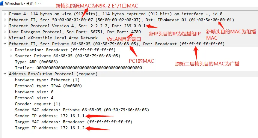
image.png
组播转发说明:
- 在N9K-1即PIM RP上,对于来自2.2.2.2并去往239.0.0.1的数据包,N9K-1会将该数据包转发至E1/2和E1/3接口;
- 同理,从任何源去往239.0.0.1数据包,数据包都会被转发到所有其它加入组播组239.0.0.1的VTEP;
- 与基于Static Ingress Replication实现VxLAN不同,基于Multicast实现VxLAN中的BUM流量由Underlay的组播网络传输;
- 最佳实践:使用Anycast RP以实现RP的负载均衡和冗余(本实验未使用Anycast RP),下图为Cisco Nexus交换机Anycast RP配置示例:
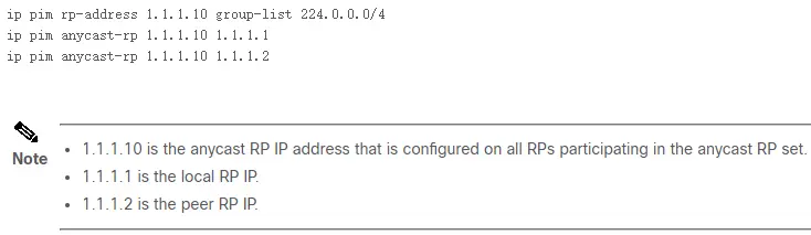
image.png
2.5.2 单播报文分析
- 对N9K-2的E1/1口抓包;
单播报文抓包:
以ARP回复报文为例
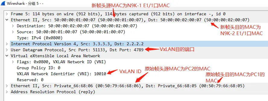
image.png
三、集中式网关
- 目标:N9K-2作为集中式网关,更改PC3的IP为172.16.2.1,实现PC3能与PC1、PC2互访;
- 不再演示外部路由设备作为网关,外部路由设备作为网关可参考实验1;
- 不再演示抓包。
变更N9K-2的配置:
feature interface-vlan
vlan 20
  vn-segment 10020
interface Vlan10
  no shutdown
  ip address 172.16.1.254/24
interface Vlan20
  no shutdown
  ip address 172.16.2.254/24
interface nve1
  member vni 10020
    mcast-group 239.0.0.2
变更N9K-4的配置:
vlan 20
  vn-segment 10020
interface nve1
  no member vni 10010
  member vni 10020
    mcast-group 239.0.0.2
interface Ethernet1/2
  switchport access vlan 20
变更PC1的配置-配上网关:
VPCS> ip 172.16.1.1 255.255.255.0  172.16.1.254
Checking for duplicate address...
PC1 : 172.16.1.1 255.255.255.0 gateway 172.16.1.254
变更PC2的配置-配上网关:
VPCS> ip 172.16.1.2 255.255.255.0  172.16.1.254
Checking for duplicate address...
PC1 : 172.16.1.2 255.255.255.0 gateway 172.16.1.254
变更PC3的配置-修改IP:
VPCS> ip 172.16.2.1 255.255.255.0  172.16.2.254
Checking for duplicate address...
PC1 : 172.16.2.1 255.255.255.0 gateway 172.16.2.254
测试:
从PC3 ping PC1
VPCS> ping  172.16.1.1
84 bytes from 172.16.1.1 icmp_seq=1 ttl=63 time=44.051 ms
84 bytes from 172.16.1.1 icmp_seq=2 ttl=63 time=52.670 ms
84 bytes from 172.16.1.1 icmp_seq=3 ttl=63 time=94.949 ms
84 bytes from 172.16.1.1 icmp_seq=4 ttl=63 time=48.976 ms
84 bytes from 172.16.1.1 icmp_seq=5 ttl=63 time=50.364 ms
从PC3 ping PC2
VPCS> ping  172.16.1.2
84 bytes from 172.16.1.2 icmp_seq=1 ttl=63 time=66.403 ms
84 bytes from 172.16.1.2 icmp_seq=2 ttl=63 time=68.189 ms
84 bytes from 172.16.1.2 icmp_seq=3 ttl=63 time=67.867 ms
84 bytes from 172.16.1.2 icmp_seq=4 ttl=63 time=86.699 ms
84 bytes from 172.16.1.2 icmp_seq=5 ttl=63 time=75.751 ms
从PC2 ping PC1
VPCS> ping 172.16.1.1
84 bytes from 172.16.1.1 icmp_seq=1 ttl=64 time=41.983 ms
84 bytes from 172.16.1.1 icmp_seq=2 ttl=64 time=46.274 ms
84 bytes from 172.16.1.1 icmp_seq=3 ttl=64 time=40.682 ms
84 bytes from 172.16.1.1 icmp_seq=4 ttl=64 time=51.736 ms
84 bytes from 172.16.1.1 icmp_seq=5 ttl=64 time=44.748 ms
如果集中式网关配置完毕并检查无误后,如果不通,可尝试保存并重启N9K!
四、总结
基于Static Ingress Replications实现VxLAN优势:
- VTEP的受控部署;
- 简化故障排除流程。
基于Static Ingress Replications实现VxLAN劣势:
- 配置和维护负担增加;
- 必须在每个VTEP上手工配置每个peer,容易出现配置错误。
基于Multicast实现VxLAN优势:
- 减少配置和维护负担;
- 具有灵活的可扩展性;
- 有效减少VTEP上行链路带宽占用,因为VTEP仅需将BUM流量的一份副本发给RP,RP再转发给其它VTEP;
- 配置简单,流量触发后自动建立VxLAN隧道。
基于Multicast实现VxLAN劣势:
- 每个VNI使用一个组播组;
- 使用组播协议会增加排错复杂性。


 1260
1260

 被折叠的 条评论
为什么被折叠?
被折叠的 条评论
为什么被折叠?
 到【灌水乐园】发言


