


原文
6.4.4 Upstream Bandwidth Allocation Map (MAP)
There are two versions of MAP messages. MAP messages with a version number of 1 are understood by DOCSIS 1.0, 1.1, 2.0, 3.0, and 3.1 equipment and are used for bandwidth allocation on TDMA and S-CDMA upstream channels. MAP messages with a version number of 5 are understood only by DOCSIS 3.1 equipment and are used
for bandwidth allocation on OFDMA upstream channels. OFDMA channels are allocated into probe frames and non-probe frames. OFDMA bandwidth allocation for non-probe frames is very similar to Version 1 MAPs. OFDMA bandwidth allocation for probe frames uses a different substructure, called a Probe MAP (P-MAP), for allocating symbols to probes. The CMTS switches between MAP and P-MAP substructures as needed for bandwidth allocation on OFDMA channels. The CMTS MUST NOT fragment MAP messages or P-MAP messages regardless of the message version.
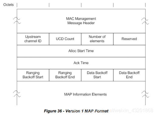
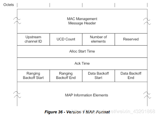
A CMTS MUST generate Version 1 MAPs in the format shown in Figure 36 - Version 1 MAP Format.
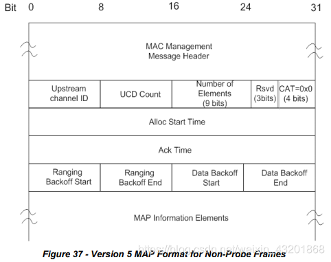
A CMTS MUST generate Version 5 MAPs for non-probe frames in the format shown in Figure 37 - Version 5 MAP Format for Non-Probe Frames.

The parameters of version 1 MAP messages and version 5 MAP messages for non-probe frames that are transmitted by a CMTS MUST include:
Upstream Channel ID: The identifier of the upstream channel to which this message refers.
UCD Count: Matches the value of the Configuration Change Count of the UCD which describes the burst parameters which apply to this MAP. See Section 11.1.
Number of Elements: Number of information elements in the MAP. This field is 8 bits in version 1 MAPs and 9 bits in version 5 MAPs. For MAPs covering non-probe frames, the maximum value of this field is 240 in version 1 MAPs and 490 for version 5 (CAT=0) MAPs. For MAPs covering probe frames (version 5, CAT=1), the maximum
value of this field is 128.
Reserved: Reserved field for 32-bit boundary alignment. This field is an 8-bit field in version 1 MAPs and a 3-bit field in version 5 MAPs.
Channel Allocation Type (CAT): Set to 0 to signify that the information elements contained in the MAP describe transmit opportunities other than probe opportunities. This field is not present in Version 1 MAPs.
Alloc Start Time: Effective start time from CMTS initialization (in minislots) for assignments within this map.
Ack Time: Latest time, from CMTS initialization (in minislots) processed in the upstream. This time is used by the CMs for collision detection purposes. See Section 7.2.2.
Ranging Backoff Start: Initial back-off window for initial ranging contention, expressed as a power of two. Values range 0-15 (the highest order bits are unused and set to 0).
Ranging Backoff End: Final back-off window for initial ranging contention is expressed as a power of two. Values range 0-15 (the highest order bits are unused and set to 0).
Data Backoff Start: Initial back-off window for contention data and requests, expressed as a power of two. Values range 0-15 (the highest order bits are unused and set to 0). See Section 7.2.2.1.2, for an explanation of how this value is used by DOCSIS 3.0 CMs operating in Multiple Transmit Channel Mode to determine backoff on a bonding group.
Data Backoff End: Final back-off window for contention data and requests, expressed as a power of two. Values range 0-15 (the highest order bits are be unused and set to 0). See Section 7.2.2.1.2 for an explanation of how this value is used by DOCSIS 3.0 CMs operating in Multiple Transmit Channel Mode to determine backoff on a bonding group.
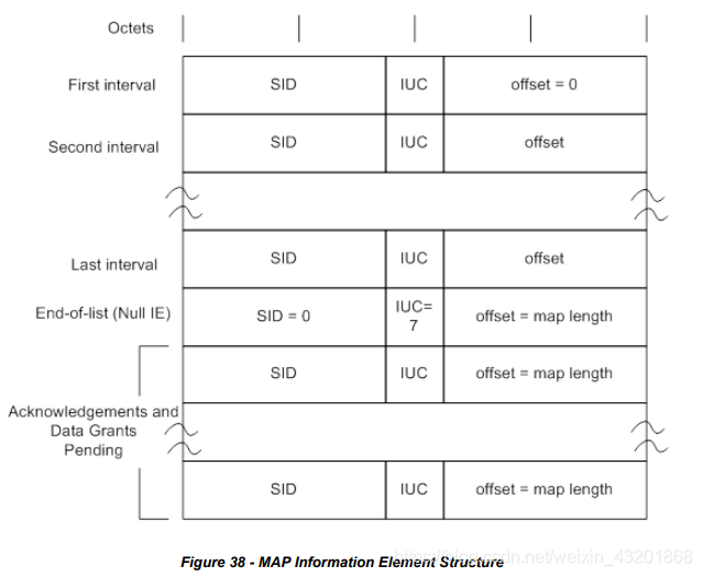
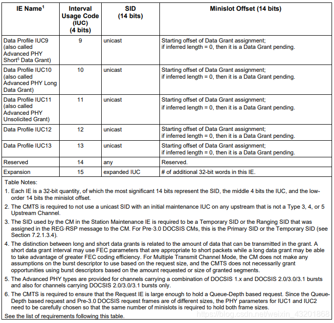
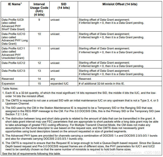
MAP Information Elements: Describe the specific usage of upstream intervals as detailed below:The CMTS MUST comply with Figure 38 - MAP Information Element Structure and Table 32 - Allocation MAP Information Elements (IE) for MAP Information Elements. Values for IUCs are defined in Table 32 and are described in detail in Section 7.2.1.3.
NOTE: Refer to Section 7.2.1.2, The Allocation MAP MAC Management Message, for the relationship between Alloc Start/Ack Time and the timebase.
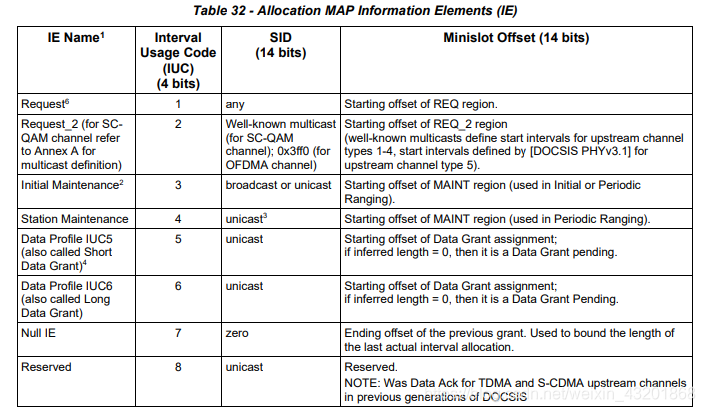
The following requirements apply to Table 32:
The CMTS MUST NOT use a unicast SID with an initial maintenance IUC on any upstream that is not a Type 3, 4, or 5 Upstream Channel.
The CM MUST use either a Temporary SID or the Ranging SID that was assigned in the REG-RSP message to the CM, in the ranging request transmitted in the ‘Station Maintenance’ Allocation MAP Information Element.
The CMTS MUST ensure that the ‘Request’ Allocation MAP Information Element is large enough to hold a Queue-Depth based request.
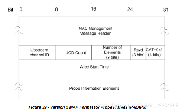
For allocating bandwidth in OFDMA probe frames, the CMTS MUST generate Version 5 MAPs in the format shown in Figure 39 - Version 5 MAP Format for Probe Frames (P-MAPs).
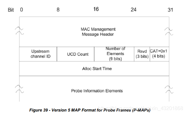
The parameters of probe frame MAP messages transmitted by a CMTS MUST include:
Upstream Channel ID: This 8-bit field is the identifier of the upstream channel to which this message refers.
UCD Count: Matches the value of the Configuration Change Count of the UCD which describes the burst parameters which apply to this map. See Section 11.1.
Number of Elements: This 9-bit field is the number of information elements in the P-MAP. The maximum value for this field is 128 for P-MAPs.
Reserved: Reserved field for 32-bit boundary alignment. This field is a 3-bit field in version 5 P-MAPs.
Channel Allocation Type (CAT): Set to 1 in all P-MAPs to designate this MAP as describing probe transmit opportunities. This field is 4 bits.
Alloc Start Time: Effective start time from CMTS initialization (in minislots) for assignments within this map. This is the first minislot of the first probe frame described in the P-MAP.
Probe Information Elements (P-IE): Describe the specific usage of symbols within a probe frame as detailed
below:
The CMTS MUST comply with Figure 40 - Probe Information Element Structure and Table 33 - Probe Information Element Definition for Probe Information Elements.
NOTE: Refer to Section 7.2.1.2, the Allocation MAP MAC Management Message, for the relationship between Alloc Start Time and the timebase.
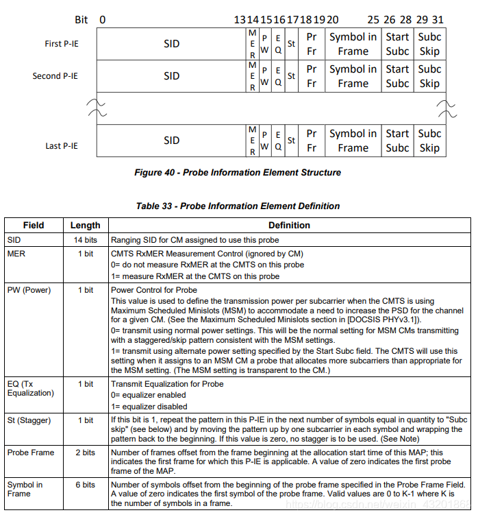
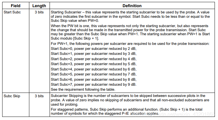
The CM MUST use power levels listed below when transmitting subcarriers used for probe transmission when the value of the Power (PW) bit of the Probe Information Element is 1 and when the value of the Start Subc field of the Upstream Bandwidth Allocation MAP is as indicated:
Start Subc=0, power per subcarrier reduced by 2 dB,
Start Subc=1, power per subcarrier reduced by 3 dB,
Start Subc=2, power per subcarrier reduced by 4 dB,
Start Subc=3, power per subcarrier reduced by 5 dB,
Start Subc=4, power per subcarrier reduced by 6 dB,
Start Subc=5, power per subcarrier reduced by 7 dB,
Start Subc=6, power per subcarrier reduced by 8 dB,
Start Subc=7, power per subcarrier reduced by 9 dB.
The CMTS MUST list Probe Information Elements in time-order (earliest symbol first) and subcarrier order (lowest subcarrier first). The CMTS MAY specify staggered patterns that cross probe frame boundaries. The CMTS MAY leave any number of probe symbols unallocated. The CMTS MUST NOT allocate bandwidth such that there are more than K P-IEs outstanding per CM and per individual OFDMA channel where K is the number of symbols in the OFDMA frame.
A DOCSIS 3.1 CM MUST be capable of storing K P-IEs per OFDMA channel. The CM MUST NOT transmit in any excluded subcarrier. When a probe staggered pattern lands on an excluded subcarrier, the CM MUST skip that point in the pattern and continue the pattern as if it had transmitted in the excluded subcarrier.
All P-IEs in the same P-MAP to the same SID are considered as one probe from a ranging perspective.
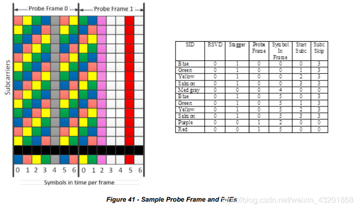
The following graphic and table in Figure 41 show example Probe frames and the corresponding P-IEs for those probe frames. In this example, there are 7 symbols per frame in the time domain and 16 subcarriers in the frequency domain with one of those subcarriers (shown in black in Figure 41) representing an excluded subcarrier. Unallocated probe symbols are shown in white. This example could be extended to any number of subcarriers. In this example,the CMTS is intending to repeat the probe pattern for the blue, green, yellow, and salmon CMs so that the CMTS receives two probe symbols per subcarrier from each of these CMs in the set of probe frames. For the medium gray CM, the CMTS wants all subcarriers probed simultaneously. In this example, the CMTS does not need to probe more than the 7 CMs shown and decides to leave unallocated the 3 probe symbols (shown in white) in the second frame. Note that when the CMTS assigns multiple probing opportunities to a CM in the same OFDMA frame (as in the repeated probe pattern for the blue, green, yellow, and salmon CMs), the CMTS uses the same PW, St, Start Subc, and Subc Skip values, as per [DOCSIS PHYv3.1].

Additional Probe Examples:
For the examples below, subcarriers 0-144 are excluded subcarriers.
• Example 1A. PW=0, ST=0, Start Subc=0, Subc Skip=2
CM transmits on subcarriers 147, 150, 153, … with normal power setting.
• Example 1B. PW=1, ST=0, Start Subc=0, Subc Skip=2
CM transmits on subcarriers 147, 150, 153, … with power reduced by 2dB.
• Example 2A. PW=0, ST=0, Start Subc=1, Subc Skip=2
CM transmits on subcarriers 145, 148, 151, … with normal power setting.
• Example 2B. PW=1, ST=0, Start Subc=1, Subc Skip=2
CM transmits on subcarriers 145, 148, 151, … with power reduced by 3dB.
• Example 3A. PW=0, ST=1, Start Subc=1, Subc Skip=2
CM transmits on subcarriers 145, 148, 151, … with normal power setting in this symbol. CM transmits on
subcarriers 146, 149, 152,… with normal power setting in the next symbol. CM transmits on subcarriers 147, 150, 153… with normal power setting in the subsequent symbol.
• Example 3B. PW=1, ST=1, Start Subc=1, Subc Skip=2
CM transmits on subcarriers 145, 148, 151, … with power reduced by 3dB in this symbol. CM transmits on subcarriers 146, 149, 152,… with power reduced by 3dB in the next symbol. CM transmits on subcarriers 147, 150, 153… with power reduced by 3dB in the subsequent symbol.
• Example 4A. PW=0, ST=0, Start Subc=6, Subc Skip=2
Not allowed.
• Example 4B. PW=1, ST=0, Start Subc=6, Subc Skip=2
CM transmits on subcarriers 147, 150, 153, … with power reduced by 8dB.
• Example 5A. PW=0, ST=0, Start Subc=4, Subc Skip=2
Not allowed.
• Example 5B. PW=1, ST=0, Start Subc=4, Subc Skip=2
CM transmits on subcarriers 145, 148, 151, … with power reduced by 6dB.
• Example 6A. PW=0, ST=1, Start Subc=4, Subc Skip=2
Not allowed.
• Example 6B. PW=1, ST=1, Start Subc=4, Subc Skip=2
CM transmits on subcarriers 145, 148, 151, … with power reduced by 6dB in this symbol. CM transmits on subcarriers 146, 149, 152,… with power reduced by 6dB in the next symbol. CM transmits on subcarriers 147, 150, 153… with power reduced by 6dB in the subsequent symbol.
6.4.4.1 Upstream Quiet Probe Measurement
For Proactive Network Maintenance (PNM) and upstream profile evaluation, the CMTS MUST provide the capability to measure the upstream channel during “quiet” symbol times when no CM is actively transmitting,permitting accurate measurement of the underlying noise, intermods and ingress. In order to facilitate this condition,the CMTS MAY use a well-known ranging SID, denoted the “idle SID”, that is not assigned to any CM on that OFDMA channel. When the CMTS needs to measure the quiet time, it allocates one or more “quiet” probe symbols in a P-MAP to the idle SID. The quiet symbols normally include all subcarriers across the upstream OFDMA channel.
翻译
6.4.4上行带宽分配图(MAP)
有两种版本的MAP消息。DOCSIS 1.0、1.1、2.0、3.0和3.1设备理解版本号为1的MAP消息,并将其用于TDMA和S-CDMA上行信道上的带宽分配。版本号为5的MAP消息仅有DOCSIS 3.1设备理解并用于在OFDMA上行信道上分配带宽。OFDMA信道被分为探测帧(probe frames)和非探测帧(non-probe frames)。非探测帧的OFDMA带宽分配与版本1 MAP非常相似。探测帧的OFDMA带宽分配使用称为探测MAP(P-MAP)的不同子结构,用于为探针分配符号。 CMTS根据需要在OFDM和DMA子结构之间切换,以在OFDMA信道上分配带宽。 无论消息版本如何,CMTS均不得将MAP消息或P-MAP消息分段。
CMTS必须以图36(版本1 MAP格式)所示的格式生成版本1 MAP。
CMTS必须为非探测帧生成版本5 MAP,格式如图37(非探测帧的版本5 MAP格式)所示。
CMTS发送的非探测帧的版本1 MAP消息和版本5 MAP消息的参数必须包括:
上行信道ID :此消息所指的上行信道的标识符。
UCD计数:与UCD的配置更改计数(Configuration Change Count)值匹配,该值描述了适用于此MAP的突发参数。参见11.1节。
元素数量(Number of Elements):MAP中信息元素(IE)的数量。在第1版MAP中此字段为8位,在第5版MAP中此字段为9位。对于覆盖非探测帧的MAP,此字段的最大值在版本1 MAP中为240,在版本5(CAT = 0)MAP中为490。对于覆盖探测帧(版本5,CAT = 1)的MAP,该字段的最大值为128。
保留(Reserved):用于32位边界对齐(boundary alignment)的保留字段。此字段在版本1 MAP中是8位字段,在版本5 MAP中是3位字段。
信道分配类型(CAT):设置为0表示MAP中包含的信息元素描述了探测机会以外的传输机会(即CAT=0就是non-probe frames)。在版本1 MAP中不存在此字段。
分配开始时间(Alloc Start Time):从CMTS初始化(在最小时隙)开始的有效开始时间,用于此map中的分配。
确认时间(Ack Time):CMTS在上行进行初始化(在minislot)的最近一次的时间。CM将这段时间用于冲突检测(collision detection)。参见7.2.2节。
范围退避开始(Ranging Backoff Start):初始范围争用的初始回退窗口,表示为2的幂。值范围为0-15(最高位未使用且设置为0)。
范围退避结束(Ranging Backoff end):初始范围争用的最终回退窗口,表示为2的幂。值范围为0-15(最高位未使用且设置为0)。
数据退避开始(Data Backoff Start):争用数据和请求的初始回退窗口,表示为2的幂。值范围为0-15(最高位未使用且设置为0)。有关在多传输信道模式下运行的DOCSIS 3.0 CM如何使用此值确定绑定组(bonding group)上的回退的解释,请参见7.2.2.1.2节。
数据退避结束(Data Backoff End):争用数据和请求的最终回退窗口,表示为2的幂。值范围为0-15(最高位未使用且设置为0)。有关在多传输信道模式下运行的DOCSIS 3.0 CM如何使用此值确定绑定组上的回退的解释,请参见7.2.2.1.2节。
MAP信息元素(MAP Information Elements):描述上行间隔的具体用法,如下所述:
CMTS必须遵守图38(MAP信息元素结构)和表32(MAP信息元素(IE))进行MAP信息元素的分配。 IUC的值在表32中定义,并在7.2.1.3节中详细描述。
注意:有关“分配开始/确认时间”与时基(timebase)之间的关系,请参见第7.2.1.2节“MAP MAC管理消息的分配”。
以下要求适用于表32:
CMTS不得在非3类,4类或5类上行信道的任何上行使用带有初始维护IUC的单播SID。
在“站维护”(Station Maintenance)分配MAP信息元素中发送的测距请求中,CM必须使用在REG-RSP消息中分配给CM的临时SID或测距SID。
CMTS必须确保“请求”分配的MAP信息元素足够大,可以容纳基于队列深度的请求(Queue-Depth based request)。
为了在OFDMA探测帧中分配带宽,CMTS必须生成图39(探测帧的版本5MAP格式(P-MAP))中所示格式的版本5MAP。
CMTS发送的探测帧MAP消息的参数必须包括:
上行信道ID :此8位字段是MAP消息引用的上行信道的标识符。
UCD计数:与UCD的配置更改计数的值匹配,该值描述了应用于此map的突发参数。参见11.1节。
元素数量:此9位字段是P-MAP中信息元素的数量。对于P-MAP,此字段的最大值为128。
保留(Reserved):用于32位边界对齐的保留字段。在版本5 P-MAP中,此字段是3位字段。
信道分配类型(CAT):在所有P-MAP中设置为1,以将该MAP指定为描述探测传输机会(describing probe transmit opportunities)。该字段是4位。
Alloc Start Time:从CMTS初始化(在最小时隙)开始的有效开始时间,用于此map中的分配。这是P-MAP中描述的第一个探测帧的第一个小时隙。
探测信息元素(P-IE):详细描述探测帧内符号(symbols)的具体用法如下:
对于探测信息元素,CMTS必须遵守图40(探测信息元素结构)和表33(探测信息元素的定义)。
注意:有关分配开始时间和时基之间的关系,请参阅第7.2.1.2节“分配MAP MAC管理消息”。
当探测信息元素的功率(PW)位的值为1且上行带宽分配MAP的Start Subc字段的值如所下所示时,CM在发射用于探测传输的子载波时必须使用下面列出的功率电平:
Start Subc = 0,每个子载波的功率降低2 dB,
Start Subc = 1,每个子载波的功率降低3 dB,
Start Subc = 2,每个子载波的功率降低4 dB,
Start Subc = 3,每个子载波的功率降低5 dB,
Start Subc = 4,每个子载波的功率降低6 dB,
Start Subc = 5,每个子载波的功率降低7 dB,
Start Subc = 6,每个子载波的功率降低8 dB,
Start Subc = 7,每个子载波的功率降低9 dB。
CMTS必须按时间顺序(最早的符号在前)和子载波顺序(最低的子载波在前)列出探测信息元素。CMTS可以规定跨探测帧边界的交错模式。CMTS可以保留任何数量的未分配探测符号。CMTS分配带宽时,不可以让每个CM和每个单独的OFDMA信道有超过K个P-IE,其中K是OFDMA帧中的符号数。
DOCSIS 3.1 CM必须能够在每个OFDMA信道上存储K个P-IE。 CM不得在任何被排除的子载波中发送。当探测交错模式落在被排除的子载波上时,CM务必跳过模式中的该点,并继续该模式,就好像它已经在被排除的子载波中发送一样。
从测距的角度来看,同一P-MAP中相同SID的所有P-IE均被视为一个探测器。
图41中的以下图形和表格显示了示例探测帧以及这些探测帧的相应P-IE。在该示例中,时域中每帧有7个符号,而频域中每帧有16个子载波,其中这些子载波中的一个(图41中用黑色显示)表示排除的子载波。未分配的探针符号以白色显示。该示例可以扩展到任意数量的子载波。在此示例中,CMTS打算对蓝色,绿色,黄色和浅橙色的CM重复探测模式,以使CMTS每个子载波从一组探测帧中的每个CM中接收到两个探测符号。对于中间灰色部分的CM,CMTS希望同时探测所有子载波。在此示例中,CMTS不需要探测超过所示的7个CM,并决定在第二帧中保留未分配的3个探测符号(以白色显示)。请注意,当CMTS在同一OFDMA帧中为CM分配多个探测机会时(如蓝色,绿色,黄色和浅橙色CM的重复探测模式),CMTS使用相同的PW,St,Start Subc和Subc Skip值,如[DOCSIS PHYv3.1]。
其他探针示例:
对于下面的示例,子载波0-144被排除在子载波之外。
•示例1A。 PW = 0,ST = 0,Start Subc = 0,Subc Skip = 2
CM以正常功率设置在子载波147、150、153,…上进行传输。
•示例1B。 PW = 1,ST = 0,Start Subc = 0,Subc Skip = 2
CM在子载波147、150、153,…上传输功率降低了2dB。
•示例2A。 PW = 0,ST = 0,Start Subc = 1,Subc Skip = 2
CM以正常功率设置在子载波145、148、151,…上进行传输。
•示例2B。 PW = 1,ST = 0,Start Subc = 1,Subc Skip = 2
CM在子载波145、148、151,…上传输功率降低了3dB。
•示例3A。 PW = 0,ST = 1,Start Subc = 1,Subc Skip = 2
CM在此符号中以正常功率设置在子载波145、148、151,…上进行传输。 CM继续传送
子载波146、149、152,…,在下一个符号中设置正常功率。 CM在子载波147、150、153 …上进行传输,并在后续符号中设置正常功率。。
•示例3B。 PW = 1,ST = 1,Start Subc = 1,Subc Skip = 2
CM在子载波145、148、151,…上进行传输,在此符号中功率降低了3dB。 CM在子载波146、149、152,…上传输,功率在下一个符号中降低3dB。 CM在子载波147、150、153 …上传输,其功率在后续符号中降低3dB。
•示例4A。 PW = 0,ST = 0,Start Subc = 6,Subc Skip = 2
不允许。
•示例4B。 PW = 1,ST = 0,Start Subc = 6,Subc Skip = 2
CM在子载波147、150、153,…上传输功率降低了8dB。
•示例5A。 PW = 0,ST = 0,Start Subc = 4,Subc Skip = 2
不允许。
•示例5B。 PW = 1,ST = 0,Start Subc = 4,Subc Skip = 2
CM在子载波145、148、151,…上传输功率降低了6dB。
•示例6A。 PW = 0,ST = 1,Start Subc = 4,Subc Skip = 2
不允许。
•示例6B。 PW = 1,ST = 1,Start Subc = 4,Subc Skip = 2
CM在子载波145、148、151,…上进行传输,在此符号中功率降低了6dB。 CM在子载波146、149、152,…上传输,功率在下一个符号中降低6dB。 CM在子载波147、150、153 …上传输,其功率在后续符号中降低6dB。
6.4.4.1 Upstream Quiet Probe Measurement
为了进行主动网络维护(PNM)和上行配置文件评估,CMTS必须提供当没有CM在主动传输(actively transmitting)的“静默”(quiet)符号时间内测量上行信道的能力,以允许对潜在的噪声(underlying noise),互调(intermods)和入口(ingress)进行准确的测量。为了促进这种情况,CMTS可以使用一个众所周知的测距SID,称为“空闲SID”,它没有分配给该OFDMA信道上的任何CM。当CMTS需要测量静默时间(quiet time)时,它会将P-MAP中的一个或多个“静默”(quiet)探测符号分配给空闲SID。静默符号通常包括跨上行OFDMA信道的所有子载波。


 被折叠的 条评论
为什么被折叠?
被折叠的 条评论
为什么被折叠?
 到【灌水乐园】发言


