


一、MGRE介绍
mGRE(Multipoint GRE)隧道是一种p2mp(点到多点)的连接,基于GRE技术的升级版。只需要配置一个tunnel接口就可以与多个站点建立GRE隧道,通常用于跨公共网络的全网状互联。mGRE的核心就隧道的NBMA地址(隧道外层公网地址)是通过NHRP(下一跳解析协议)协议动态获知的,无需手动配置。NHRP用于解析的是tunnel IP(逻辑地址)到NBMA地址(物理地址/真实地址)的映射。通常Hub(总部)作为NHS,负责接收和存储Spoke(分支机构)的NHRP注册信息,响应Spoke的NHRP解析请求。
二、MGRE基本原理和实现
多点通信:MGRE允许在IP网络中建立多个点对多个点的通信连接。这意味着可以在一个MGRE隧道中同时传输多个源和目的地之间的数据。
封装:MGRE使用封装技术将源站点的数据包封装在一个或多个IP包中。这些封装的IP包通过IP网络传输到目的站点。
路由:MGRE使用路由协议来确定数据包从源站点到目的站点的路径。常见的路由协议有OSPF(Open Shortest Path First)和BGP(Border Gateway Protocol)。
解封装:目的站点接收到封装的IP包后,将其解封装,提取出源站点的数据包,并将其传递给目的站点。
多点互联:MGRE还支持多个MGRE隧道之间的互联,以实现更复杂的网络拓扑结构。
三、MGRE小实验
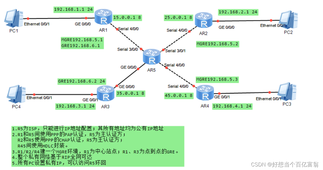
1. R1、R2、R3、R4、R5的IP配置
[R1]int g0/0/0
[R1-GigabitEthernet0/0/0]ip address 192.168.1.1 24
[R1-GigabitEthernet0/0/0]int s4/0/0
[R1-Serial4/0/0]ip address 15.0.0.1 8

[R2]int g0/0/0
[R2-GigabitEthernet0/0/0]ip address 192.168.2.1 24
[R2-GigabitEthernet0/0/0]int s4/0/0
[R2-Serial4/0/0]ip address 25.0.0.1 8

[R3]int g0/0/1
[R3-GigabitEthernet0/0/1]ip address 192.168.3.1 24
[R3-GigabitEthernet0/0/1]int g0/0/0
[R3-GigabitEthernet0/0/0]ip address 35.0.0.1 8

[R4]int g0/0/1
[R4-GigabitEthernet0/0/1]ip address 192.168.4.1 24
[R4-GigabitEthernet0/0/1]int s4/0/0
[R4-Serial4/0/0]ip address 45.0.0.1 8

[ISP]int s3/0/0
[ISP-Serial3/0/0]ip address 15.0.0.2 8
[ISP-Serial3/0/0]int s3/0/1
[ISP-Serial3/0/1]ip address 25.0.0.2 8
[ISP-Serial3/0/1]int g0/0/0
[ISP-GigabitEthernet0/0/0]ip address 35.0.0.1 8
[ISP-GigabitEthernet0/0/0]int s4/0/0
[ISP-Serial4/0/0]ip address 45.0.0.2 8
2. R1与R5间PPP的PAP认证
[ISP]aaa                                             //主认证方
[ISP-aaa]local-user haha password cipher 123123.     //建立一个用户admin
[ISP-aaa]local-user haha service-type ppp            //认证类型ppp
[ISP-aaa]q
[ISP]int s3/0/0
[ISP-Serial3/0/0]ppp authentication-mode pap	     //开启pap认证

[R1]int s4/0/0                                       //被认证方
[R1-Serial4/0/0]ppp pap local-user haha password cipher 123123
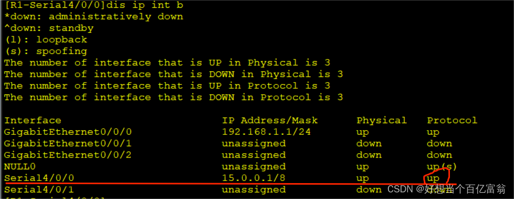
由于PPP的会话是一次性的,会话建立成功之后,再修改参数(认证信息之类)不影响会话,即会话不断开。R1和R5之间本身的认证类型也是PPP,所以为了验证PPP的PAP认证是否建立成功,先断开会话再重新建立。
[r1-Serial4/0/0]shutdown
[r1-Serial4/0/0]undo shutdown
最后查看R1
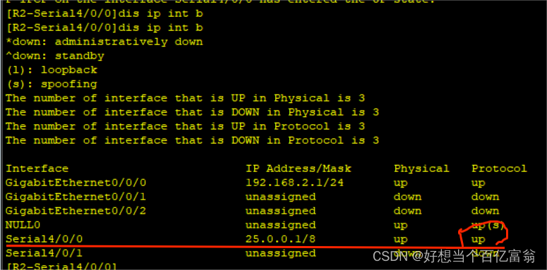
3. R2与R5间PPP的CHAP认证
[ISP]int s3/0/1                //主认证方
[ISP-Serial3/0/1]ppp authentication-mode chap     //创建的这个haha账号即用于R1又分配给R2

[R2]int s4/0/0
[R2-Serial4/0/0]ppp chap user haha
[R2-Serial4/0/0]ppp chap password cipher 123123
同样也shutdown再undo shutdown,然后查看R2
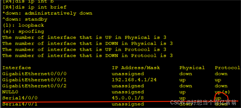
4. R4与R5间的HDLC封装
[ISP]int s4/0/0
[ISP-Serial4/0/0]link-protocol hdlc   //改二层封装协议为HDLC
Warning: The encapsulation protocol of the link will be changed. Continue? [Y/N]
:y

[R4]int s4/0/0
[R4-Serial4/0/0]link-protocol hdlc
Warning: The encapsulation protocol of the link will be changed. Continue? [Y/N]
:y
查看R4
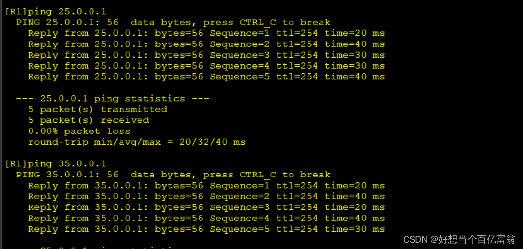
4. 写缺省,保证公网全通
[R1]ip route-static 0.0.0.0 0 15.0.0.2
[R2]ip route-static 0.0.0.0 0 25.0.0.2
[R3]ip route-static 0.0.0.0 0 35.0.0.2
[R4]ip route-static 0.0.0.0 0 45.0.0.2
测试是否全通

5. R1、R2、R4的MGRE隧道配置
[R1]int Tunnel 0/0/0      //创建Tunnel接口
[R1-Tunnel0/0/0]ip address 192.168.5.1 24     //配置接口ip地址
[R1-Tunnel0/0/0]tunnel-protocol gre p2mp      //修改接口模式为多点GRE
[R1-Tunnel0/0/0]source 15.0.0.1         //定义公有的源IP地址
[R1-Tunnel0/0/0]nhrp network-id 100      //默认为0号,该网段内所有节点tunnel接口必须为相同域

[R2]int Tunnel 0/0/0
[R2-Tunnel0/0/0]ip address 192.168.5.2 24
[R2-Tunnel0/0/0]tunnel-protocol gre p2mp
[R2-Tunnel0/0/0]source s4/0/0       //源ip不固定,所以写出接口
[R2-Tunnel0/0/0]nhrp network-id 100
[R2-Tunnel0/0/0]nhrp entry 192.168.5.1 15.0.0.1 register   //告知中心的虚拟ip和真实ip

[R4]int Tunnel 0/0/0
[R4-Tunnel0/0/0]ip address 192.168.5.4 24
[R4-Tunnel0/0/0]tunnel-protocol gre p2mp
[R4-Tunnel0/0/0]source s4/0/0
[R4-Tunnel0/0/0]nhrp network-id 100
[R4-Tunnel0/0/0]nhrp entry 192.168.5.1 15.0.0.1 register
6. R1、R3的GRE隧道配置
[R1]int Tunnel 0/0/1
[R1-Tunnel0/0/1]ip address 192.168.6.1 24
[R1-Tunnel0/0/1]tunnel-protocol gre
[R1-Tunnel0/0/1]source 15.0.0.1
[R1-Tunnel0/0/1]destination 35.0.0.1

[R3]int Tunnel 0/0/1
[R3-Tunnel0/0/1]ip address 192.168.6.2 24
[R3-Tunnel0/0/1]tunnel-protocol gre
[R3-Tunnel0/0/1]source 35.0.0.1
[R3-Tunnel0/0/1]destination 15.0.0.1
7. R1、R2、R3、R4跑rip宣告直连网段
[R1]rip 1
[R1-rip-1]version 2
[R1-rip-1]network 192.168.1.0
[R1-rip-1]network 192.168.5.0
[R1-rip-1]network 192.168.6.0

[R2]rip 1
[R2-rip-1]version 2
[R2-rip-1]network 192.168.2.0
[R2-rip-1]network 192.168.5.0

[R3]rip 1
[R3-rip-1]version 2
[R3-rip-1]network 192.168.3.0
[R3-rip-1]network 192.168.6.0

[R4]rip 1
[R4-rip-1]version 2
[R4-rip-1]network 192.168.4.0
[R4-rip-1]network 192.168.5.0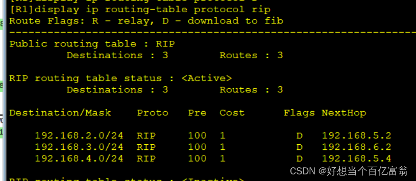
注:
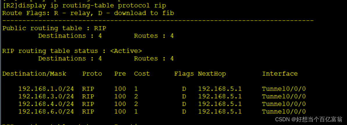
R2、R3、R4查不到的原因是由于RIP 的水平分割,关闭RIP的水平分割就可以查到。
8. 分支间路由信息获取不全,关闭R1的rip水平分割
[R1]int Tunnel 0/0/0
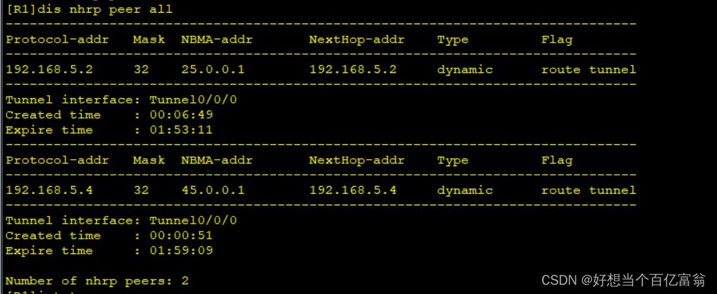
[R1-Tunnel0/0/0]nhrp entry multicast dynamic //本地成为NHRP中心,同时可以进行伪广播
[R1-Tunnel0/0/0]undo rip split-horizon
就可以查询到
9. 做nat进行地址转换使运营商有私网的路由
[R1]acl 2000
[R1-acl-basic-2000]rule permit source 192.168.1.0 0.0.0.255
[R1]interface s4/0/0
[R1-Serial4/0/0]nat outbound 2000

[R2]acl 2000
[R2-acl-basic-2000]rule permit source 192.168.2.0 0.0.0.255
[R2-Serial4/0/0]nat outbound 2000

[R3]acl 2000
[R3-acl-basic-2000]rule permit source 192.168.3.0 0.0.0.255
[R3]int g0/0/0
[R3-GigabitEthernet0/0/0]nat outbound 2000

[R4]acl 2000
[R4-acl-basic-2000]rule permit source 192.168.4.0 0.0.0.255
[R4]int s4/0/0
[R4-Serial4/0/0]nat outbound 2000
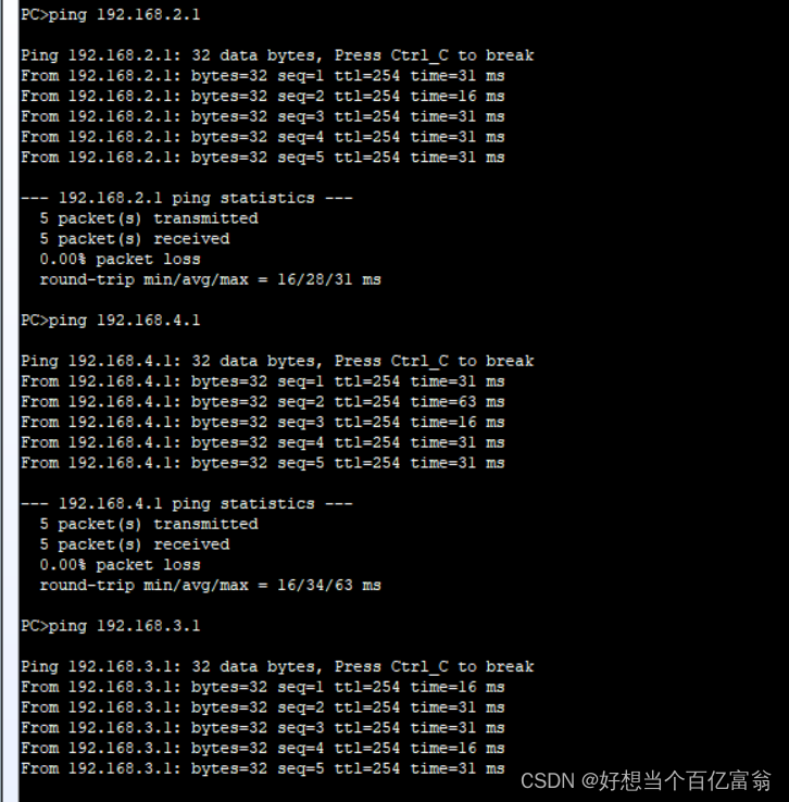
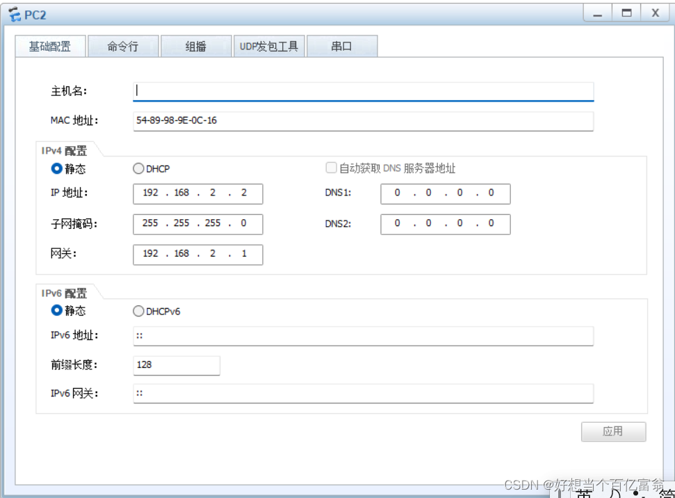
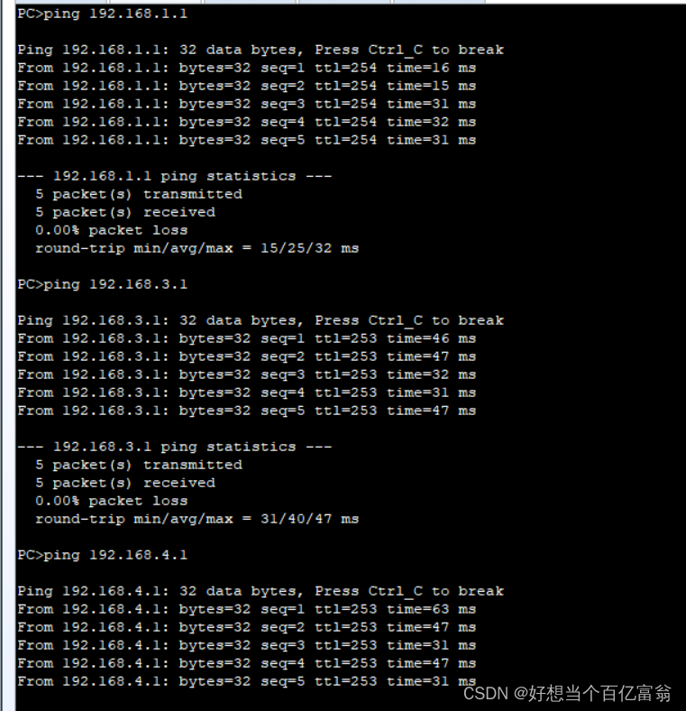
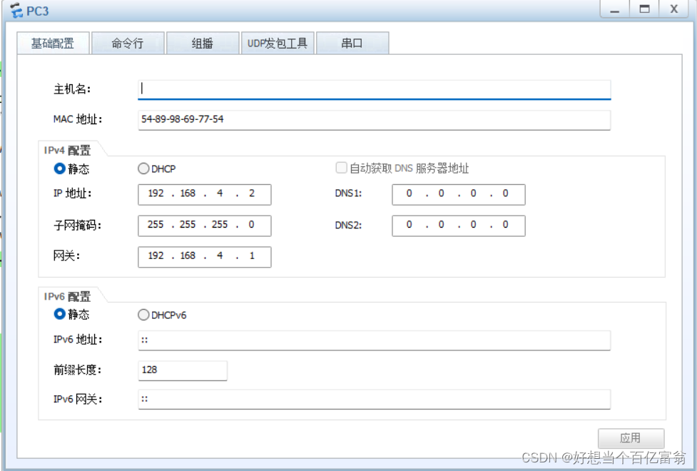
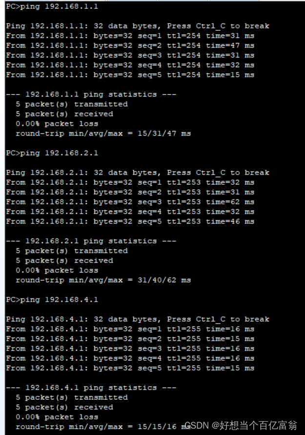
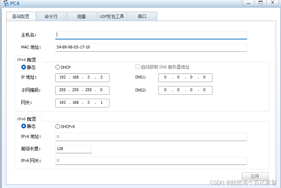
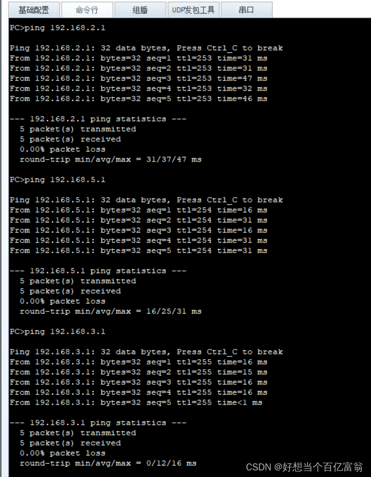
10. 对PC1、PC2、PC3、PC4配置并进行ping测试
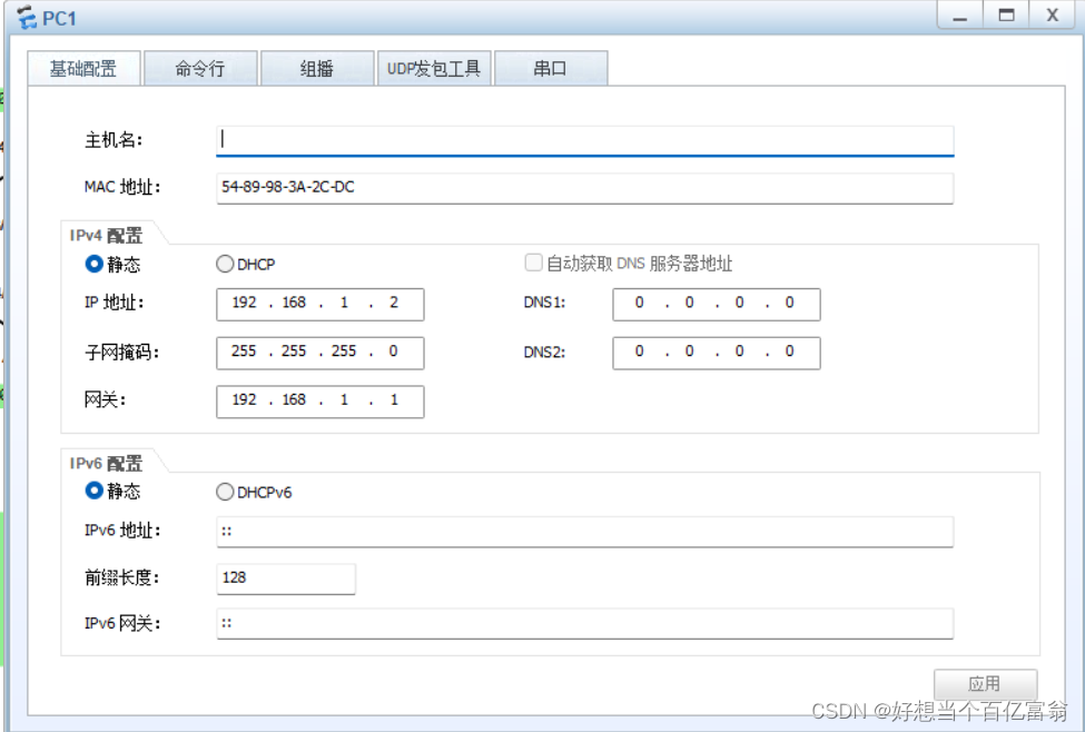
PC2
PC3
PC4


 1142
1142


 被折叠的 条评论
为什么被折叠?
被折叠的 条评论
为什么被折叠?
 到【灌水乐园】发言


