


实验题目:三层架构实验
实验要求:
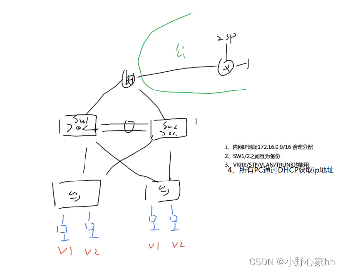
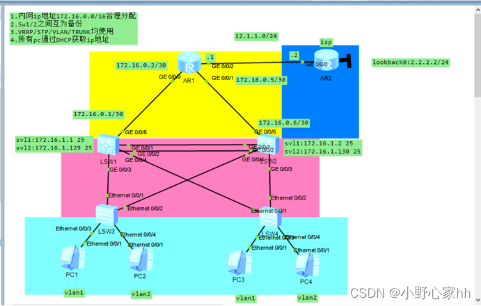
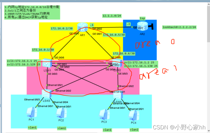
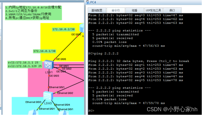
- 内网ip地址172.16.0.0/16合理分配
- Sw1/2之间互为备份
- VRRP/STP/VLAN/TRUNK均使用
- 所有pc通过DHCP获取ip地址
实验拓扑:
实验思路:
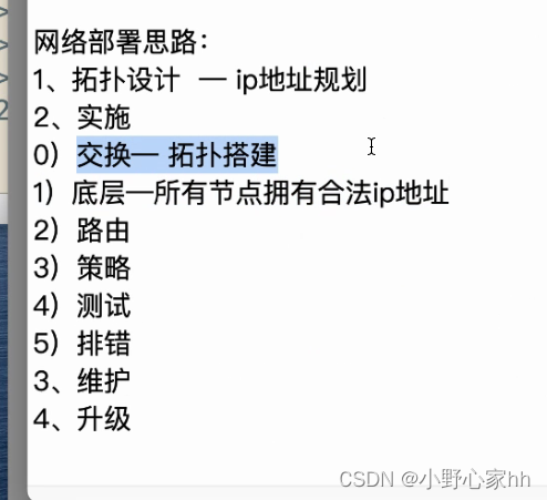
- 先配置access 和通道,然后配置trunk,之后配置STP,svl和vrrp,接着是dhcp,之后再搞定路由和外网
- 内网ip地址的划分:
基于172.16.0.0/16
172.16.0.0/30
172.16.1.0/17 172.16.1.0/25 vlan1
172.16.1.128/17 172.16.1.128/25 vlan2
实验内容:
- 先在各交换机上创建vlan2 再将连接对应pc的接口划分到vlan2
[sw1]vlan 2
[sw2]vlan 2
[sw3]vlan 2
[sw3-Ethernet0/0/4]port link-type access
[sw3-Ethernet0/0/4]port default vlan 2
[sw4]vlan 2
[sw4-Ethernet0/0/4]port link-type access
[sw4-Ethernet0/0/4]port default vlan 2
2.在两台三层交换机上创建通道
[sw1]interface Eth-Trunk 0 创建通道接口
[sw1-Eth-Trunk0]q
[sw1]interface GigabitEthernet 0/0/1 将物理接口加入到通道内
[sw1-GigabitEthernet0/0/1]eth-trunk 0
[sw1-GigabitEthernet0/0/1]int g0/0/2
[sw1-GigabitEthernet0/0/2]eth-trunk 0
[sw2]interface Eth-Trunk 0
[sw2-Eth-Trunk0]q
[sw2]interface GigabitEthernet 0/0/1
[sw2-GigabitEthernet0/0/1]eth-trunk 0
[sw2-GigabitEthernet0/0/1]int g0/0/2
[sw2-GigabitEthernet0/0/2]eth-trunk 0
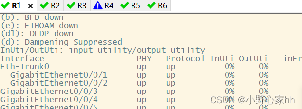
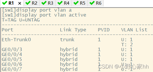
3.配置trunk干道
[sw1]interface Eth-Trunk 0
[sw1-Eth-Trunk0]port link-type trunk
[sw1-Eth-Trunk0]port trunk allow-pass vlan all
[sw1]interface g0/0/3
[sw1-GigabitEthernet0/0/4]port link-type trunk
[sw1-GigabitEthernet0/0/4]port trunk allow-pass vlan all
[sw1]interface g0/0/4
[sw1-GigabitEthernet0/0/4]port link-type trunk
[sw1-GigabitEthernet0/0/4]port trunk allow-pass vlan all
[sw2]interface Eth-Trunk 0
[sw2-Eth-Trunk0]port link-type trunk
[sw2-Eth-Trunk0]port trunk allow-pass vlan all
[sw2]interface g0/0/3
[sw2-GigabitEthernet0/0/4]port link-type trunk
[sw2-GigabitEthernet0/0/4]port trunk allow-pass vlan all
[sw2]interface g0/0/4
[sw2-GigabitEthernet0/0/4]port link-type trunk
[sw2-GigabitEthernet0/0/4]port trunk allow-pass vlan all
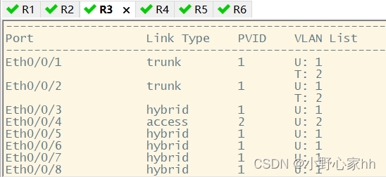
[sw3]interface e0/0/2
[sw3-Ethernet0/0/2]port link-type trunk
[sw3-Ethernet0/0/2]port trunk allow-pass vlan all
[sw3]interface e0/0/3
[sw3-Ethernet0/0/3]port link-type trunk
[sw3-Ethernet0/0/3]port trunk allow-pass vlan all
[sw4]interface e0/0/2
[sw4-Ethernet0/0/2]port link-type trunk
[sw4-Ethernet0/0/2]port trunk allow-pass vlan all
[sw4]interface e0/0/3
[sw4-Ethernet0/0/3]port link-type trunk
[sw4-Ethernet0/0/3]port trunk allow-pass vlan all
4.配置mstp生成树
在四台交换机上都要配置
并且让sw1和sw2互为备份
[sw1]stp enable
[sw1]stp region-configuration
[sw1-mst-region]region-name a
[sw1-mst-region]instance 1 vlan 1
[sw1-mst-region]instance 2 vlan 2
[sw1-mst-region]active region-configuration
[sw1]stp instance 1 root primary
[sw1]stp instance 2 root secondary
[sw2]stp enable
[sw2]stp region-configuration
[sw2-mst-region]region-name a
[sw2-mst-region]instance 1 vlan 1
[sw2-mst-region]instance 2 vlan 2
[sw2-mst-region]active region-configuration
[sw2]stp instance 1 root secondary
[sw2]stp instance 2 root primary
[sw3]stp enable
[sw3]stp region-configuration
[sw3-mst-region]region-name a
[sw3-mst-region]instance 1 vlan 1
[sw3-mst-region]instance 2 vlan 2
[sw3-mst-region]active region-configuration
[sw4]stp enable
[sw4]stp region-configuration
[sw4-mst-region]region-name a
[sw4-mst-region]instance 1 vlan 1
[sw4-mst-region]instance 2 vlan 2
[sw4-mst-region]active region-configuration
顺便将连接pc的接口调到边缘接口
[sw3]interface GigabitEthernet 0/0/3
[sw3-GigabitEthernet0/0/1]stp edged-port enable
[sw3]interface GigabitEthernet 0/0/4
[sw3-GigabitEthernet0/0/1]stp edged-port enable
[sw4]interface GigabitEthernet 0/03
[sw4-GigabitEthernet0/0/1]stp edged-port enable
[sw4]interface GigabitEthernet 0/0/4
[sw4-GigabitEthernet0/0/1]stp edged-port enable
5.配置svl接口
[sw1-Vlanif1]ip add 172.16.1.1 25
[sw1-Vlanif2]ip add 172.16.1.129 25
[sw2-Vlanif2]ip add 172.16.1.12 25
[sw2-Vlanif2]ip add 172.16.1.130 25
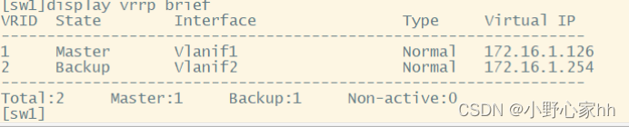
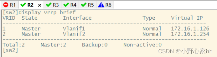
6.配置VRRP
[sw1]interface Vlanif 1
[sw1-Vlanif1]vrrp vrid 1 virtual-ip 172.16.1.126
[sw1-Vlanif1]vrrp vrid 1 priority 120
[sw1-Vlanif1]vrrp vrid 1 track interface GigabitEthernet 0/0/5 reduced 30
[sw1]interface Vlanif 2
[sw1-Vlanif2]vrrp vrid 2 virtual-ip 172.16.1.254
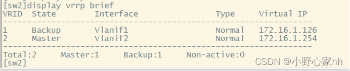
[sw2]interface Vlanif 1
[sw2-Vlanif1]vrrp vrid 1 virtual-ip 172.16.1.126
[sw2]interface Vlanif 2
[sw2-Vlanif2]vrrp vrid 2 virtual-ip 172.16.1.254
[sw2-Vlanif2]vrrp vrid 2 priority 120
[sw2-Vlanif2]vrrp vrid 2 track interface GigabitEthernet 0/0/5 reduced 30
7.配置DHCP池塘
[sw1]dhcp enable
[sw1]ip pool v1
[sw1-ip-pool-v1]network 172.16.1.0 mask 25
[sw1-ip-pool-v1]gateway-list 172.16.1.126
[sw1-ip-pool-v1]dns-list 114.114.114.114 8.8.8.8
[sw1]ip pool v2
[sw1-ip-pool-v1]network 172.16.1.128 mask 25
[sw1-ip-pool-v1]gateway-list 172.16.1.254
[sw1-ip-pool-v1]dns-list 114.114.114.114 8.8.8.8
[sw1]int vlan 1
[sw1-Vlanif1]dhcp select global
[sw1-Vlanif1]int vlan 2
[sw1-Vlanif2]dhcp select global
[sw2]dhcp enable
[sw2]ip pool v1
[sw2-ip-pool-v1]network 172.16.1.0 mask 25
[sw2-ip-pool-v1]gateway-list 172.16.1.126
[sw2-ip-pool-v1]dns-list 114.114.114.114 8.8.8.8
[sw2]ip pool v2
[sw2-ip-pool-v1]network 172.16.1.128 mask 25
[sw2-ip-pool-v1]gateway-list 172.16.1.254
[sw2-ip-pool-v1]dns-list 114.114.114.114 8.8.8.8
[sw2]int vlan 1
[sw2-Vlanif1]dhcp select global
[sw2-Vlanif1]int vlan 2
[sw2-Vlanif2]dhcp select global
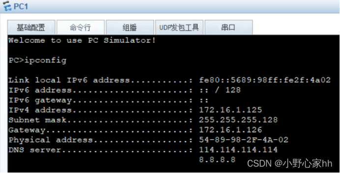
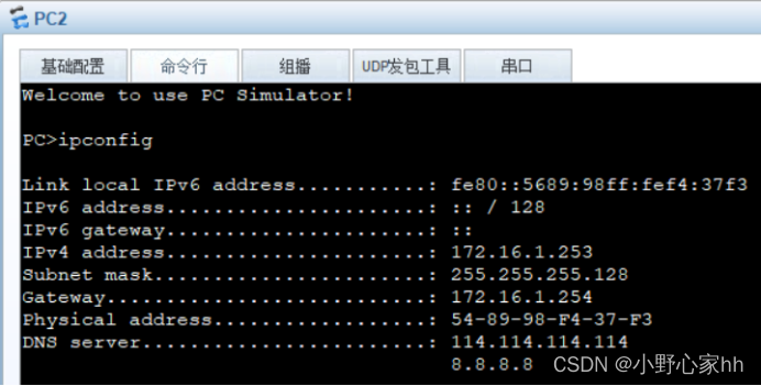
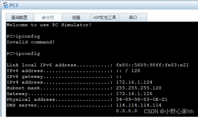
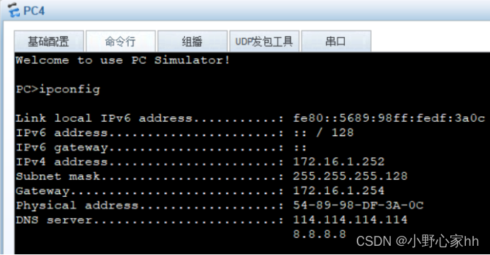
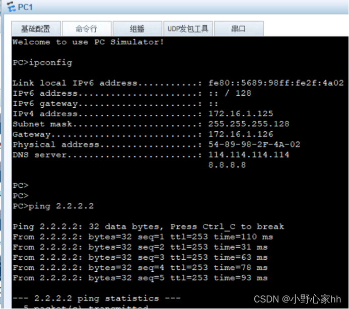
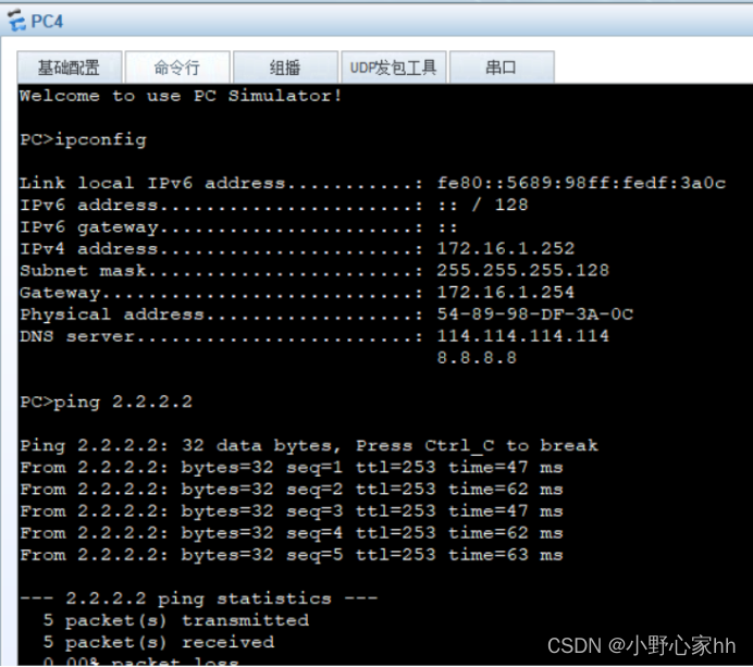
此时pc都已经获取到正确的地址
8.为交换机配置三层接口
[sw1]vlan 100
[sw1-GigabitEthernet0/0/5]po l a
[sw1-GigabitEthernet0/0/5]p d vlan 100
[sw1-GigabitEthernet0/0/5]int vlan 100
[sw1-Vlanif100]ip ad 172.16.0.1 30
[sw2]vlan 100
[sw2-GigabitEthernet0/0/5]p l a
[sw2-GigabitEthernet0/0/5]p d vlan 100
[sw2-GigabitEthernet0/0/5]int vlan 100
[sw2-Vlanif100]ip ad 172.16.0.6 30
9、为路由器配置ip地址
[r1]interface g0/0/0
[r1-GigabitEthernet0/0/0]ip add 172.16.0.2 30e.
[r1-GigabitEthernet0/0/0]int g0/0/1
[r1-GigabitEthernet0/0/1]ip add 172.16.0.5 30
[r1-GigabitEthernet0/0/1]int g0/0/2
[r1-GigabitEthernet0/0/2]ip add 12.1.1.1 24
[isp]interface LoopBack 0
[isp-LoopBack0]ip add 2.2.2.2 24[isp-LoopBack0]int
[isp-LoopBack0]int g0/0/0
[isp-GigabitEthernet0/0/0]ip add 12.1.1.2 24
10、启动opsf
此时根据层次划分ospf的两个区域,分为区域0和区域1
[r2]ospf 1 router-id 1.1.1.1
[r2-ospf-1]area 0
[r2-ospf-1-area-0.0.0.0]network 172.16.0.0 0.0.0.255
[sw1]ospf 1 router-id 1.1.1.2
[sw1-ospf-1]area 0
[sw1-ospf-1-area-0.0.0.0]network 172.16.0.1 0.0.0.0
[sw1-ospf-1-area-0.0.0.0]q
[sw1-ospf-1]area 1
[sw1-ospf-1-area-0.0.0.1]network 172.16.1.1 0.0.0.0
[sw1-ospf-1-area-0.0.0.1]network 172.16.1.129 0.0.0.0
[sw2]ospf 1 router-id 2.2.2.2
[sw2-ospf-1]area 0
[sw2-ospf-1-area-0.0.0.0]network 172.16.0.6 0.0.0.0
[sw2-ospf-1-area-0.0.0.0]q
[sw2-ospf-1]area 1
[sw2-ospf-1-area-0.0.0.1]network 172.16.1.2 0.0.0.0
[sw2-ospf-1-area-0.0.0.1]network 172.16.1.130 0.0.0.0
顺便做好路由汇总:
汇总:
[sw1]ospf 1
[sw1-ospf-1]area 1
[sw1-ospf-1-area-0.0.0.1]abr-summary 172.16.1.0 255.255.255.0
[sw2]ospf 1
[sw2-ospf-1]area 1
[sw2-ospf-1-area-0.0.0.1]abr-summary 172.16.1.0 255.255.255.0
设置沉默接口:
[sw1]ospf 1
[sw1-ospf-1]silent-interface all
[sw1-ospf-1]undo silent-interface GigabitEthernet 0/0/5
[sw1-ospf-1]undo silent-interface Eth-Trunk 0
[sw1-ospf-1]undo silent-interface vlanif 1
[sw1-ospf-1]undo silent-interface vlanif 100
[sw2]ospf 1
[sw2-ospf-1]silent-interface all
[sw2-ospf-1]undo silent-interface GigabitEthernet 0/0/5
[sw2-ospf-1]undo silent-interface Eth-Trunk 0
[sw2-ospf-1]undo silent-interface vlanif 1
[sw2-ospf-1]undo silent-interface vlanif 100
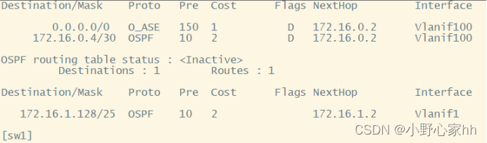
11.缺省路由
[r1]ip route-static 0.0.0.0 0.0.0.0 12.1.1.2
[r1]ospf 1
[r1-ospf-1]default-route-advertise
此时:sw1已经学到了缺省路由
12.配置NAT
让pc可以访问公网
[r1]acl 2000
[r1-acl-basic-2000]rule permit source 172.16.0.0 0.0.255.255
[r1-acl-basic-2000]int g0/0/2
[r1-GigabitEthernet0/0/2]nat outbound 2000
此时所有的配置完成
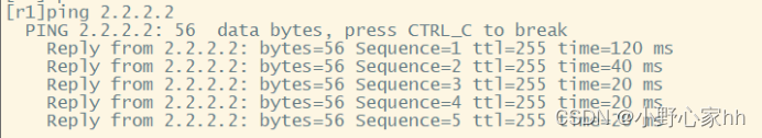
13.测试
此时关闭交换机sw1
此时sw2成为根网桥


 5696
5696


 被折叠的 条评论
为什么被折叠?
被折叠的 条评论
为什么被折叠?
 到【灌水乐园】发言


