


 本文详细介绍了如何在华为交换机上配置LACP模式的链路聚合,以提升SwitchA和SwitchB之间的带宽与可靠性,确保VLAN间的通信。包括创建Eth-Trunk、设置系统优先级、配置活动接口和备份链路等关键步骤。
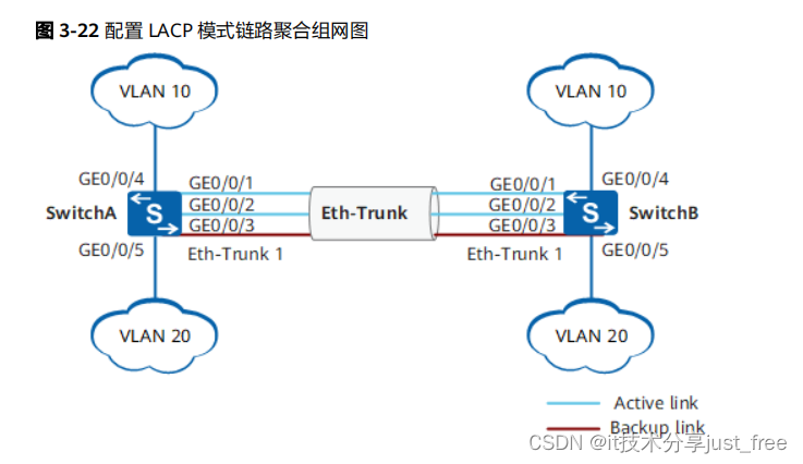
组网需求
如
图
3-22所示,SwitchA和SwitchB通过以太链路分别都连接VLAN10和VLAN20的网络,且SwitchA和SwitchB之间有较大的数据流量。用户希望SwitchA和SwitchB之间能够提供较大的链路带宽来使相同VLAN间互相通信。在两台Switch设备上配置LACP模式链路聚合组,提高两设备之间的带宽与可靠性,具体要求如下:
● 两条活动链路具有负载分担的能力。
● 两设备间的链路具有1条冗余备份链路,当活动链路出现故障时,备份链路替代故障链路,保持数据传输的可靠性。
● 同VLAN间可以相互通信。
配置思路
采用如下的思路配置LACP模式链路聚合:
1. 创建Eth-Trunk,配置Eth-Trunk为LACP模式,实现链路聚合功能。
2. 将成员接口加入Eth-Trunk。
3. 配置系统优先级,确定主动端,按照主动端设备的接口选择活动接口。
4. 配置活动接口上限阈值,实现保证带宽的情况下提高网络的可靠性。
5. 配置接口优先级,确定活动链路接口,优先级高的接口将被选作活动接口。
6. 创建VLAN并将接口加入VLAN。
操作步骤
步骤
1 在SwitchA上创建Eth-Trunk1并配置为LACP模式。SwitchB的配置与SwitchA类似,不
再赘述
<HUAWEI>
system-view
[HUAWEI]
sysname SwitchA
[SwitchA]
interface eth-trunk 1
[SwitchA-Eth-Trunk1]
mode lacp
[SwitchA-Eth-Trunk1]
quit
步骤
2 配置SwitchA上的成员接口加入Eth-Trunk。SwitchB的配置与SwitchA类似,不再赘述
[SwitchA]
interface gigabitethernet 0/0/1
[SwitchA-GigabitEthernet0/0/1]
eth-trunk 1
[SwitchA-GigabitEthernet0/0/1]
quit
[SwitchA]
interface gigabitethernet 0/0/2
[SwitchA-GigabitEthernet0/0/2]
eth-trunk 1
[SwitchA-GigabitEthernet0/0/2]
quit
[SwitchA]
interface gigabitethernet 0/0/3
[SwitchA-GigabitEthernet0/0/3]
eth-trunk 1
[SwitchA-GigabitEthernet0/0/3]
quit
步骤
3 在SwitchA上配置系统优先级为100,使其成为LACP主动端
[SwitchA]
lacp priority 100
步骤
4 在SwitchA上配置活动接口上限阈值为2
[SwitchA]
interface eth-trunk 1
[SwitchA-Eth-Trunk1]
max active-linknumber 2
[SwitchA-Eth-Trunk1]
quit
步骤
5 在SwitchA上配置接口优先级确定活动链路
[SwitchA]
interface gigabitethernet 0/0/1
[SwitchA-GigabitEthernet0/0/1]
lacp priority 100
[SwitchA-GigabitEthernet0/0/1]
quit
[SwitchA]
interface gigabitethernet 0/0/2
[SwitchA-GigabitEthernet0/0/2]
lacp priority 100
[SwitchA-GigabitEthernet0/0/2]
quit
步骤
6 创建VLAN并将接口加入VLAN。
# 创建VLAN10和VLAN20并分别加入接口。SwitchB的配置与SwitchA类似,不再赘
述。
[SwitchA]
vlan batch 10 20
[SwitchA]
interface gigabitethernet 0/0/4
[SwitchA-GigabitEthernet0/0/4]
port link-type trunk
[SwitchA-GigabitEthernet0/0/4]
port trunk allow-pass vlan 10
[SwitchA-GigabitEthernet0/0/4]
quit
[SwitchA]
interface gigabitethernet 0/0/5
[SwitchA-GigabitEthernet0/0/5]
port link-type trunk
[SwitchA-GigabitEthernet0/0/5]
port trunk allow-pass vlan 20
[SwitchA-GigabitEthernet0/0/5]
quit
# 配置Eth-Trunk1接口允许VLAN10和VLAN20通过。SwitchB的配置与SwitchA类似,
不再赘述。
[SwitchA]
interface eth-trunk 1
[SwitchA-Eth-Trunk1]
port link-type trunk
[SwitchA-Eth-Trunk1]
port trunk allow-pass vlan 10 20
[SwitchA-Eth-Trunk1]
quit
步骤
7 验证配置结果
# 查看各Switch设备的Eth-Trunk信息,查看链路是否协商成功。
[SwitchA]
display eth-trunk 1
Eth-Trunk1's state information is:
Local:
LAG ID:
1 WorkingMode:
LACP
Preempt Delay: Disabled Hash arithmetic: According to SIP-XOR-DIP
System Priority:
100 System ID: 00e0-fca8-0417
Least Active-linknumber: 1 Max Active-linknumber: 2
Operate status:
up Number Of Up Port In Trunk: 2
--------------------------------------------------------------------------------
ActorPortName Status PortType PortPri PortNo PortKey PortState Weight
GigabitEthernet0/0/1
Selected 1GE 100 6145 2865 11111100 1
GigabitEthernet0/0/2
Selected 1GE 100 6146 2865 11111100 1
GigabitEthernet0/0/3
Unselect 1GE 32768 6147 2865 11100000 1
Partner:
--------------------------------------------------------------------------------
ActorPortName SysPri SystemID PortPri PortNo PortKey PortState
GigabitEthernet0/0/1 32768 00e0-fca6-7f85 32768 6145 2609 11111100
GigabitEthernet0/0/2 32768 00e0-fca6-7f85 32768 6146 2609 11111100
GigabitEthernet0/0/3 32768 00e0-fca6-7f85 32768 6147 2609 11110000
[SwitchB]
display eth-trunk 1
Eth-Trunk1's state information is:
Local:
LAG ID:
1 WorkingMode:
LACP
Preempt Delay: Disabled Hash arithmetic: According to SIP-XOR-DIP
System Priority: 32768 System ID: 00e0-fca6-7f85
Least Active-linknumber: 1 Max Active-linknumber: 8
Operate status:
up Number Of Up Port In Trunk: 2
--------------------------------------------------------------------------------
ActorPortName Status PortType PortPri PortNo PortKey PortState Weight
GigabitEthernet0/0/1
Selected 1GE 32768 6145 2609 11111100 1
GigabitEthernet0/0/2
Selected 1GE 32768 6146 2609 11111100 1
GigabitEthernet0/0/3
Unselect 1GE 32768 6147 2609 11100000 1
Partner:
--------------------------------------------------------------------------------
ActorPortName SysPri SystemID PortPri PortNo PortKey PortState
GigabitEthernet0/0/1 100 00e0-fca8-0417 100 6145 2865 11111100
GigabitEthernet0/0/2 100 00e0-fca8-0417 100 6146 2865 11111100
GigabitEthernet0/0/3 100 00e0-fca8-0417 32768 6147 2865 11110000
通过以上显示信息可以看到,SwitchA的系统优先级为100,高于SwitchB的系统优先级。Eth-Trunk的成员接口中GigabitEthernet0/0/1、GigabitEthernet0/0/2成为活动接口,处于“Selected”状态,接口GigabitEthernet0/0/3处于“Unselect”状态,同时实现M条链路的负载分担和N条链路的冗余备份功能。
----
结束
配置文件
● SwitchA的配置文件
#
sysname SwitchA
#
vlan batch 10 20
#
lacp priority 100
#
interface Eth-Trunk1
port link-type trunk
port trunk allow-pass vlan 10 20
mode lacp
max active-linknumber 2
#
interface GigabitEthernet0/0/1
eth-trunk 1
lacp priority 100
#
interface GigabitEthernet0/0/2
eth-trunk 1
lacp priority 100
#
interface GigabitEthernet0/0/3
eth-trunk 1
#
interface GigabitEthernet0/0/4
port link-type trunk
port trunk allow-pass vlan 10
#
interface GigabitEthernet0/0/5
port link-type trunk
port trunk allow-pass vlan 20
#
return
● SwitchB的配置文件
#
sysname SwitchB
#
vlan batch 10 20
#
interface Eth-Trunk1
port link-type trunk
port trunk allow-pass vlan 10 20
mode lacp
#
interface GigabitEthernet0/0/1
eth-trunk 1
#
interface GigabitEthernet0/0/2
eth-trunk 1
#
interface GigabitEthernet0/0/3
eth-trunk 1
#
interface GigabitEthernet0/0/4
port link-type trunk
port trunk allow-pass vlan 10
#
interface GigabitEthernet0/0/5
port link-type trunk
port trunk allow-pass vlan 20
#
return


 2204
2204

 被折叠的 条评论
为什么被折叠?
被折叠的 条评论
为什么被折叠?
 到【灌水乐园】发言


