


原作者:renzo mischianti - 发布于2020年1月17日 - 更新于2021年6月21日
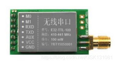
我们已经看到这个设备(基于流行的SX1276/SX1278无线模块的E32 UART LoRa)是如何管理省电的,但是如果我们只对e32使用省电,微控制器就会继续保持活跃,但是我们可以使用AUX引脚来解决这个问题。
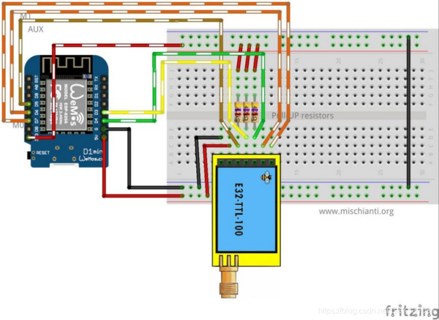
如果你有像冻结设备的麻烦,你必须把一个上拉的4.7k电阻或更好的连接到设备AUX引脚。
我们现在使用的是面包板模式,但我们要做一些修正,我们要用D3和D4代替D2和D3,这样SDA和SCL(i2c协议)就保持自由。
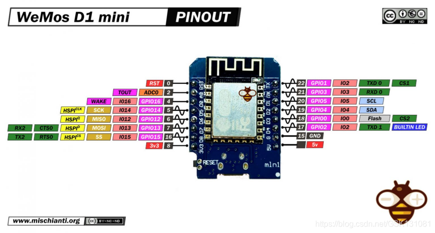
因此,新的连接模式变成这样
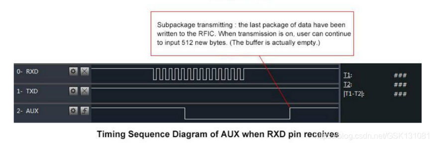
当你处于睡眠模式时,e32把接收到的数据放在缓冲区,并立即转为低电平,当数据准备好时,返回高电平,低电平,这是唤醒微控制器的最佳方式。
1. WeMos D1 mini 唤醒
作为e32设备,WeMos有一些睡眠类型,但在这个测试中,我们将使用带有GPIO唤醒的浅睡眠。
请参考 "WeMos D1 mini (esp8266),三种睡眠模式管理节能--第四部分",了解关于睡眠模式的详细说明。
1.1.如何使WeMos D1 mini进入睡眠状态
将单片机断电的命令是这样的
// Enter power down state with ADC and BOD module disabled.
// Wake up when wake up pin is low.
LowPower.powerDown(SLEEP_FOREVER, ADC_OFF, BOD_OFF);
但我们必须规定,当AUX引脚为低电平时,设备必须被唤醒。
// Allow wake up pin to trigger interrupt on low.
attachInterrupt(1, AUX_PIN, LOW);

// Enter power down state with ADC and BOD module disabled.
// Wake up when wake up pin is low.
LowPower.powerDown(SLEEP_FOREVER, ADC_OFF, BOD_OFF);

// Disable external pin interrupt on wake up pin.
detachInterrupt(1);
因此,接收传输的代码变得如此:
/*
 * LoRa E32-TTL-100
 * Receive fixed transmission message on channel and wake up.
 * https://www.mischianti.org
 *
 * E32-TTL-100----- Arduino UNO or esp8266
 * M0         ----- LOW
 * M1         ----- HIGH
 * TX         ----- RX PIN D3 (PullUP)
 * RX         ----- TX PIN D4 (PullUP)
 * AUX        ----- PIN D5
 * VCC        ----- 5v
 * GND        ----- GND
 *
 */
#include "Arduino.h"
#include "LoRa_E32.h"
#include <ESP8266WiFi.h>

#define FPM_SLEEP_MAX_TIME           0xFFFFFFF
void callback() {
  Serial.println("Callback");
  Serial.flush();
}

// ---------- esp8266 pins --------------
LoRa_E32 e32ttl(D3, D4, D5);  // Arduino RX <-- e32 TX, Arduino TX --> e32 RX
// -------------------------------------
void printParameters(struct Configuration configuration);
//The setup function is called once at startup of the sketch
void setup()
{
    Serial.begin(9600);
    while (!Serial) {
        ; // wait for serial port to connect. Needed for native USB
    }
    delay(100);

    e32ttl.begin();
        e32ttl.setMode(MODE_2_POWER_SAVING);

//  e32ttl.resetModule();
    // After set configuration comment set M0 and M1 to low
    // and reboot if you directly set HIGH M0 and M1 to program
    ResponseStructContainer c;
    c = e32ttl.getConfiguration();
    Configuration configuration = *(Configuration*) c.data;
    printParameters(configuration);

    configuration.ADDL = 3;
    configuration.ADDH = 0;
    configuration.CHAN = 0x04;
    configuration.OPTION.fixedTransmission = FT_FIXED_TRANSMISSION;
    configuration.OPTION.wirelessWakeupTime = WAKE_UP_250;

    configuration.OPTION.fec = FEC_1_ON;
    configuration.OPTION.ioDriveMode = IO_D_MODE_PUSH_PULLS_PULL_UPS;
    configuration.OPTION.transmissionPower = POWER_20;

    configuration.SPED.airDataRate = AIR_DATA_RATE_010_24;
    configuration.SPED.uartBaudRate = UART_BPS_9600;
    configuration.SPED.uartParity = MODE_00_8N1;

    e32ttl.setConfiguration(configuration, WRITE_CFG_PWR_DWN_SAVE);
    printParameters(configuration);
    // ---------------------------
    delay(1000);
    Serial.println();
    Serial.println("Start sleep!");

    //wifi_station_disconnect(); //not needed
    gpio_pin_wakeup_enable(GPIO_ID_PIN(D5), GPIO_PIN_INTR_LOLEVEL);
    wifi_set_opmode(NULL_MODE);
    wifi_fpm_set_sleep_type(LIGHT_SLEEP_T);
    wifi_fpm_open();
    wifi_fpm_set_wakeup_cb(callback);
    wifi_fpm_do_sleep(FPM_SLEEP_MAX_TIME);
    delay(1000);

    Serial.println();
    Serial.println("Start listening!");

}

// The loop function is called in an endless loop
void loop()
{
    if (e32ttl.available()  > 1){
        ResponseContainer rs = e32ttl.receiveMessage();
        // First of all get the data
        String message = rs.data;

        Serial.println(rs.status.getResponseDescription());
        Serial.println(message);
    }
}

void printParameters(struct Configuration configuration) {
    Serial.println("----------------------------------------");

    Serial.print(F("HEAD : "));  Serial.print(configuration.HEAD, BIN);Serial.print(" ");Serial.print(configuration.HEAD, DEC);Serial.print(" ");Serial.println(configuration.HEAD, HEX);
    Serial.println(F(" "));
    Serial.print(F("AddH : "));  Serial.println(configuration.ADDH, DEC);
    Serial.print(F("AddL : "));  Serial.println(configuration.ADDL, DEC);
    Serial.print(F("Chan : "));  Serial.print(configuration.CHAN, DEC); Serial.print(" -> "); Serial.println(configuration.getChannelDescription());
    Serial.println(F(" "));
    Serial.print(F("SpeedParityBit     : "));  Serial.print(configuration.SPED.uartParity, BIN);Serial.print(" -> "); Serial.println(configuration.SPED.getUARTParityDescription());
    Serial.print(F("SpeedUARTDatte  : "));  Serial.print(configuration.SPED.uartBaudRate, BIN);Serial.print(" -> "); Serial.println(configuration.SPED.getUARTBaudRate());
    Serial.print(F("SpeedAirDataRate   : "));  Serial.print(configuration.SPED.airDataRate, BIN);Serial.print(" -> "); Serial.println(configuration.SPED.getAirDataRate());

    Serial.print(F("OptionTrans        : "));  Serial.print(configuration.OPTION.fixedTransmission, BIN);Serial.print(" -> "); Serial.println(configuration.OPTION.getFixedTransmissionDescription());
    Serial.print(F("OptionPullup       : "));  Serial.print(configuration.OPTION.ioDriveMode, BIN);Serial.print(" -> "); Serial.println(configuration.OPTION.getIODroveModeDescription());
    Serial.print(F("OptionWakeup       : "));  Serial.print(configuration.OPTION.wirelessWakeupTime, BIN);Serial.print(" -> "); Serial.println(configuration.OPTION.getWirelessWakeUPTimeDescription());
    Serial.print(F("OptionFEC          : "));  Serial.print(configuration.OPTION.fec, BIN);Serial.print(" -> "); Serial.println(configuration.OPTION.getFECDescription());
    Serial.print(F("OptionPower        : "));  Serial.print(configuration.OPTION.transmissionPower, BIN);Serial.print(" -> "); Serial.println(configuration.OPTION.getTransmissionPowerDescription());

    Serial.println("----------------------------------------");

}
结果是串口在第91行停止,当我们收到信息时,e32自己唤醒并把AUX置于低位,所以Arduino用AUX引脚的中断唤醒。
这里是发射端代码:
/*
* LoRa E32-TTL-100
* Send fixed broadcast transmission message to a specified channel.
* https://www.mischianti.org
*
* E32-TTL-100----- Arduino UNO or esp8266
* M0 ----- HIGH
* M1 ----- LOW
* TX ----- RX PIN D3 (PullUP)
* RX ----- TX PIN D4 (PullUP)
* AUX ----- PIN D5
* VCC ----- 5v
* GND ----- GND
*
*/
#include "Arduino.h"
#include "LoRa_E32.h"
LoRa_E32 e32ttl(D3, D4, D5);
// -------------------------------------
void printParameters(struct Configuration configuration);
//The setup function is called once at startup of the sketch
void setup()
{
Serial.begin(9600);
while (!Serial) {
; // wait for serial port to connect. Needed for native USB
}
delay(100);
while (!e32ttl.begin()) {
delay(2000); // wait for serial port to connect. Needed for native USB
}
e32ttl.setMode(MODE_1_WAKE_UP);
// e32ttl.resetModule();
// After set configuration comment set M0 and M1 to low
// and reboot if you directly set HIGH M0 and M1 to program
ResponseStructContainer c;
c = e32ttl.getConfiguration();
Configuration configuration = *(Configuration*) c.data;
printParameters(configuration);
// configuration.SPED.uartBaudRate = UART_BPS_9600;
// configuration.SPED.airDataRate = AIR_DATA_RATE_010_24;
configuration.ADDL = 0x01;
configuration.ADDH = 0x00;
configuration.CHAN = 0x04;
configuration.OPTION.fixedTransmission = FT_FIXED_TRANSMISSION;
configuration.OPTION.wirelessWakeupTime = WAKE_UP_750;
configuration.OPTION.fec = FEC_1_ON;
configuration.OPTION.ioDriveMode = IO_D_MODE_PUSH_PULLS_PULL_UPS;
configuration.OPTION.transmissionPower = POWER_20;
configuration.SPED.airDataRate = AIR_DATA_RATE_010_24;
configuration.SPED.uartBaudRate = UART_BPS_9600;
configuration.SPED.uartParity = MODE_00_8N1;
e32ttl.setConfiguration(configuration, WRITE_CFG_PWR_DWN_SAVE);
printParameters(configuration);
// ---------------------------
}
int i = 0;
// The loop function is called in an endless loop
void loop()
{
i++;
String mess = "Message to 00 03 04 deviceMessage to ";
String compMEss = mess+i;
Serial.print(compMEss);
Serial.print(" - ");
ResponseStatus rs = e32ttl.sendFixedMessage(0, 3, 0x04, compMEss);
Serial.println(rs.getResponseDescription());
delay(8000);
}
void printParameters(struct Configuration configuration) {
Serial.println("----------------------------------------");
Serial.print(F("HEAD : ")); Serial.print(configuration.HEAD, BIN);Serial.print(" ");Serial.print(configuration.HEAD, DEC);Serial.print(" ");Serial.println(configuration.HEAD, HEX);
Serial.println(F(" "));
Serial.print(F("AddH : ")); Serial.println(configuration.ADDH, DEC);
Serial.print(F("AddL : ")); Serial.println(configuration.ADDL, DEC);
Serial.print(F("Chan : ")); Serial.print(configuration.CHAN, DEC); Serial.print(" -> "); Serial.println(configuration.getChannelDescription());
Serial.println(F(" "));
Serial.print(F("SpeedParityBit : ")); Serial.print(configuration.SPED.uartParity, BIN);Serial.print(" -> "); Serial.println(configuration.SPED.getUARTParityDescription());
Serial.print(F("SpeedUARTDatte : ")); Serial.print(configuration.SPED.uartBaudRate, BIN);Serial.print(" -> "); Serial.println(configuration.SPED.getUARTBaudRate());
Serial.print(F("SpeedAirDataRate : ")); Serial.print(configuration.SPED.airDataRate, BIN);Serial.print(" -> "); Serial.println(configuration.SPED.getAirDataRate());
Serial.print(F("OptionTrans : ")); Serial.print(configuration.OPTION.fixedTransmission, BIN);Serial.print(" -> "); Serial.println(configuration.OPTION.getFixedTransmissionDescription());
Serial.print(F("OptionPullup : ")); Serial.print(configuration.OPTION.ioDriveMode, BIN);Serial.print(" -> "); Serial.println(configuration.OPTION.getIODroveModeDescription());
Serial.print(F("OptionWakeup : ")); Serial.print(configuration.OPTION.wirelessWakeupTime, BIN);Serial.print(" -> "); Serial.println(configuration.OPTION.getWirelessWakeUPTimeDescription());
Serial.print(F("OptionFEC : ")); Serial.print(configuration.OPTION.fec, BIN);Serial.print(" -> "); Serial.println(configuration.OPTION.getFECDescription());
Serial.print(F("OptionPower : ")); Serial.print(configuration.OPTION.transmissionPower, BIN);Serial.print(" -> "); Serial.println(configuration.OPTION.getTransmissionPowerDescription());
Serial.println("----------------------------------------");
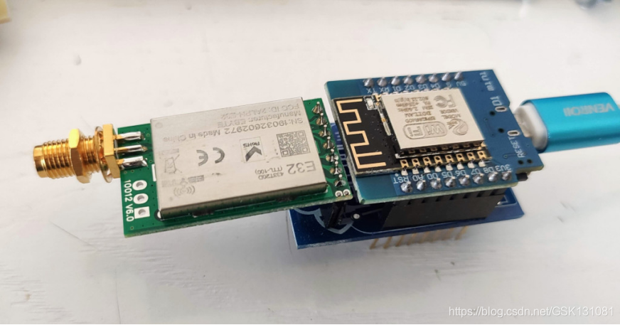
}2. WeMos D1 mini 拓展板
我还创建了一个WeMos D1mini拓展板,非常有用地使用。
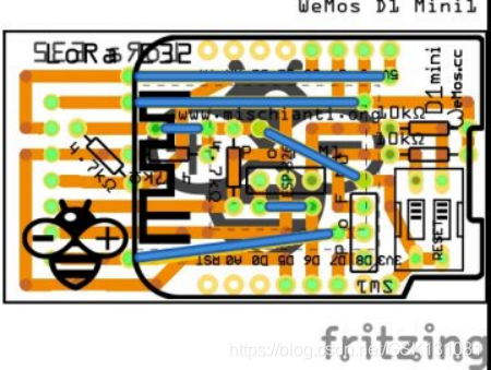
配置是这样的:
LoRa_E32 e32ttl(D3, D4, D5, D7, D6); 你可以使用库中的所有例子,你可以使用D6和D7针脚来做一个完整的连接,或者禁用它们,用拨码开关把M0和M1放在你想要的地方。
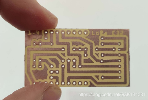
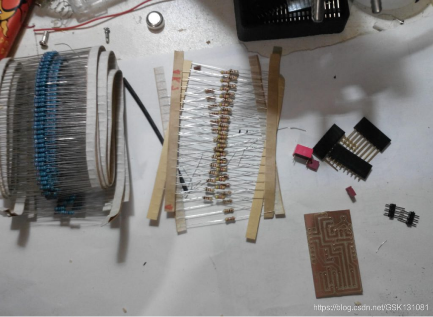
2.1.现在我们要进行焊接了
Ready to go
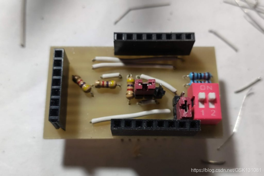
Here the result of milled PCB
Here the result with ordered PCB

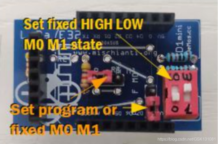
拓展板有一些跳线和拨码开关来配置M0和M1。
如果你想把M0和M1设置成一个固定的值,你必须把跳线放到F,如果你想通过引脚来控制,就把跳线放到P。
如果你设置为F,你必须把拨码开关放在属性值低或高。
2.2.购物清单

你可以从这里获得pcb,而不需要额外的费用。 PCBWay

这是我的圣诞礼物
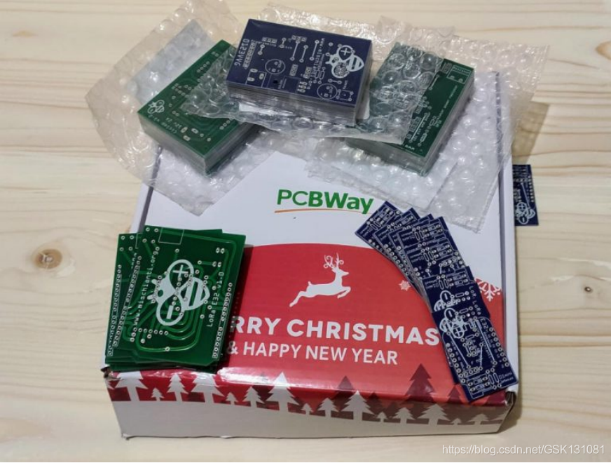
我选择这个制造商是因为在同样的成本下,它提供了优秀的质量,在第一个屏幕上,它可以做出无数的选择,适合每一个需求。
正如你在各种照片上看到的那样,这个板子非常漂亮,而且很容易焊接。
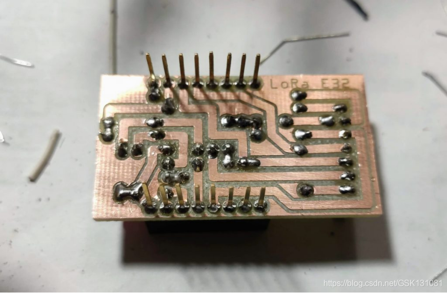
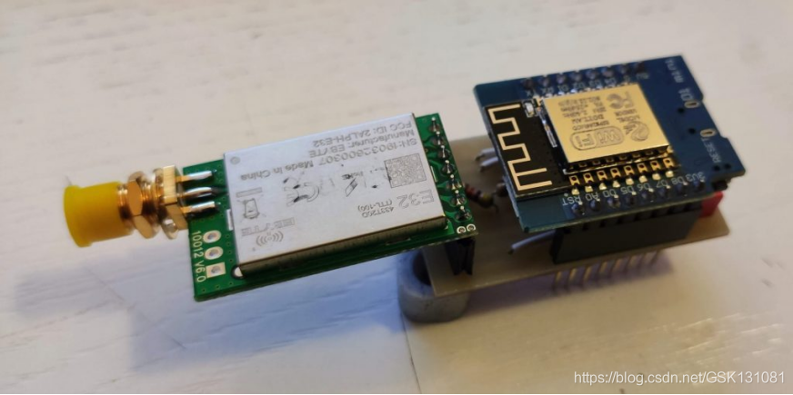
2.3.组装
Here the result
3.Thanks


 1万+
1万+


 被折叠的 条评论
为什么被折叠?
被折叠的 条评论
为什么被折叠?
 到【灌水乐园】发言


