


实验过程:
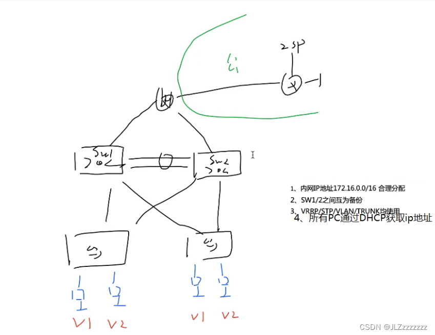
1.IP地址的规划以及拓扑的搭建
ISP:12.1.1.0/24 R2环回:2.2.2.2/24
172.16.0.0/16
骨干:172.16.0.0/24 172.16.0.0/30 172.16.0.4/30
VLAN:172.16.1.0/24 1:172.16.1.0/25 2:172.16.1.128/25
2.配置交换部分
【1】Eth-trunk配置
[sw1]interface Eth-Trunk 0 创建以太中继接口
[sw1-Eth-Trunk0]trunkport g 0/0/1 0/0/2 在eth-trunk接口中,把物理接口拉进来
同理完成SW2的配置
【2】创建VLAN
因为默认交换机中VALN 1存在,所以我们只需要创建VLAN 2
[sw1]vlan 2
同理完成SW2/3/4的配置
【3】接口划入VLAN
因为默认交换机所有接口都在VLAN 1中,所以我们只需将Ethernet0/0/2划入VLAN 2中
[sw3]int e0/0/2
[sw3-Ethernet0/0/2]port link-type access
[sw3-Ethernet0/0/2]port default vlan 2
同理完成SW4的配置
【4】trunk干道
因为默认交换机仅允许VLAN 1通过,所有我们需要让Ethernet接口允许VLAN 2通过(除了access接口)
[sw1]port-group group-member Eth-Trunk 0 Ethernet 0/0/3 to Ethernet 0/0/4
[sw1-port-group]port link-type trunk
[sw1-port-group]port trunk allow-pass vlan 2
同理完成SW2的配置
[sw3]port-group group-member Ethernet 0/0/3 to e0/0/4
[sw3-port-group]port link-type trunk
[sw3-port-group]port trunk allow-pass vlan 2
同理完成SW4的配置
【5】STP
[sw1]stp mode mstp
[sw1]stp enable
[sw1]stp region-configuration
[sw1-mst-region]region-name a
[sw1-mst-region]revision-level 100
[sw1-mst-region]instance 1 vlan 1
[sw1-mst-region]instance 2 vlan 2
[sw1-mst-region]active region-configuration
同理完成SW2/3/4的配置
进行主根和备份根的配置:
SW1:
[sw1]stp instance 1 root primary
[sw1]stp instance 2 root secondary
SW2:
[sw2]stp instance 1 root se
[sw2]stp instance 2 root p
建议连接终端的接口,使用边缘接口,可以节约30s,响应速度更快
[sw3]int e0/0/3
[sw3-Ethernet0/0/3]stp edged-port enable
[sw3-Ethernet0/0/3]int e0/0/4
[sw3-Ethernet0/0/4]stp edged-port enable
同理完成SW4的配置
【6】SVI
[sw1]int vlan 1
[sw1-Vlanif1]ip address 172.16.1.1 25
[sw1-Vlanif1]int vlan 2
[sw1-Vlanif2]ip address 172.16.1.129 25
[sw2]int vlan 1
[sw2-Vlanif1]ip address 172.16.1.2 25
[sw2-Vlanif1]int vlan 2
[sw2-Vlanif2]ip address 172.16.1.130 25
【7】VRRP
[sw1]interface Vlanif 1
[sw1-Vlanif1]vrrp vrid 1 virtual-ip 172.16.1.126
[sw1-Vlanif1]vrrp vrid 1 priority 105
[sw1-Vlanif1]vrrp vrid 1 track interface g0/0/1 reduced 10
[sw1-Vlanif1]int vlan 2
[sw1-Vlanif2]vrrp vrid 1 virtual-ip 172.16.1.254
[sw2]int vlan 1
[sw2-Vlanif1]vrrp vrid 1 virtual-ip 172.16.1.126
[sw2-Vlanif1]int vlan 2
[sw2-Vlanif2]vrrp vrid 1 virtual-ip 172.16.1.254
[sw2-Vlanif2]vrrp vrid 1 priority 105
[sw2-Vlanif2]vrrp vrid 1 track int g0/0/2 reduced 10
【8】DHCP
[sw1]dhcp enable
[sw1]ip pool v1
[sw1-ip-pool-v1]network 172.16.1.0 mask 25
[sw1-ip-pool-v1]gateway-list 172.16.1.126
[sw1-ip-pool-v1]dns-list 114.114.114.114 8.8.8.8
[sw1]ip pool v2
[sw1-ip-pool-v2]network 172.16.1.128 mask 25
[sw1-ip-pool-v2]gateway-list 172.16.1.254
[sw1-ip-pool-v2]dns-list 114.114.114.114 8.8.8.8
[sw1-ip-pool-v1]int vlan 1
[sw1-Vlanif1]dhcp select global
[sw1-Vlanif1]int vlan 2
[sw1-Vlanif2]dhcp select global
同理完成SW2的配置
3.底层–所有节点拥有合法的IP地址
[r1]int g0/0/1
[r1-GigabitEthernet0/0/1]ip address 172.16.0.1 30
[r1-GigabitEthernet0/0/1]int g0/0/2
[r1-GigabitEthernet0/0/2]ip address 172.16.0.5 30
[r1]int g0/0/0
[r1-GigabitEthernet0/0/0]ip address 12.1.1.1 24
[sw1]vlan 100
[sw1-vlan100]q
[sw1]interface vlan 100
[sw1-Vlanif100]ip address 172.16.0.2 30
[sw1]int e0/0/11
[sw1-Ethernet0/0/11]port link-type access
[sw1-Ethernet0/0/11]port default vlan 100
[sw2]vlan 100
[sw2-vlan100]q
[sw2]int vlan 100
[sw2-Vlanif100]ip address 172.16.0.6 30
[sw2]int e0/0/22
[sw2-Ethernet0/0/22]port link-type access
[sw2-Ethernet0/0/22]port default vlan 100
[ISP]int g0/0/0
[ISP-GigabitEthernet0/0/0]ip address 12.1.1.2 24
[ISP-GigabitEthernet0/0/0]int l 0
[ISP-LoopBack0]ip address 2.2.2.2 24
4.路由-全网可达
【1】在R1和SW1/2上跑个OSPF协议
【2】对不需要发送hello包保活的接口设置成沉默接口(被动接口)
[sw1-ospf-1]silent-interface all
[sw1-ospf-1]undo silent-interface Vlanif 100
[sw1-ospf-1]undo silent-interface Eth-Trunk 0
[sw1-ospf-1]undo silent-interface Vlanif 1
同理完成SW2的配置
【3】在R1上向外指一条缺省,在向内网下放一条缺省
[r1]ip route-static 0.0.0.0 0 12.1.1.2
[r1]ospf
[r1-ospf-1]default-route-advertise
【4】NAT网络地址转换
[r1]acl 2000
[r1-acl-basic-2000]rule permit source 172.16.0.0 0.0.255.255
[r1-acl-basic-2000]q
[r1]int g0/0/0
[r1-GigabitEthernet0/0/0]nat outbound 2000


 1556
1556


 被折叠的 条评论
为什么被折叠?
被折叠的 条评论
为什么被折叠?
 到【灌水乐园】发言


