


1. 想要实现的效果
CANDB++软件针对信号在一帧报文中的排布是用如下界面形式表示的。
2. 最终实现的效果
想通过PySide6在TableWidget上面绘制带箭头的直线,实现和CANDB++软件表示信号排布一样的界面效果。
3. 实现信号排布的关键技术
3.1 QTableWidget为指定单元格设置委托
在 QTableWidget 中为指定单元格设置委托并不是直接通过某个方法来实现的,因为 QTableWidget 提供的接口主要是为整行、整列或整个表格设置委托(通过 setItemDelegateForRow, setItemDelegateForColumn, 或 setItemDelegate 方法)。然而,你可以通过一些技巧来为特定的单元格实现不同的委托行为。
一种方法是使用自定义委托,并在委托内部根据单元格的索引(或其他条件)来决定如何绘制和编辑该单元格。这通常涉及到在 paint 和 createEditor 方法中添加额外的逻辑。
委托是一种用于绘制和编辑数据的对象,它允许你自定义单元格的显示和编辑行为。
自定义委托通常用于以下情况:
当你需要改变单元格的绘制方式时,比如改变文本的颜色、字体,或者添加图标、背景色等。
当你需要为单元格提供自定义的编辑器,比如一个下拉列表、一个日期选择器或是一个滑块。
当你需要处理复杂的交互逻辑,比如点击单元格时显示一个工具提示,或者实现拖放功能。
4. 验证信号排布代码的有效性
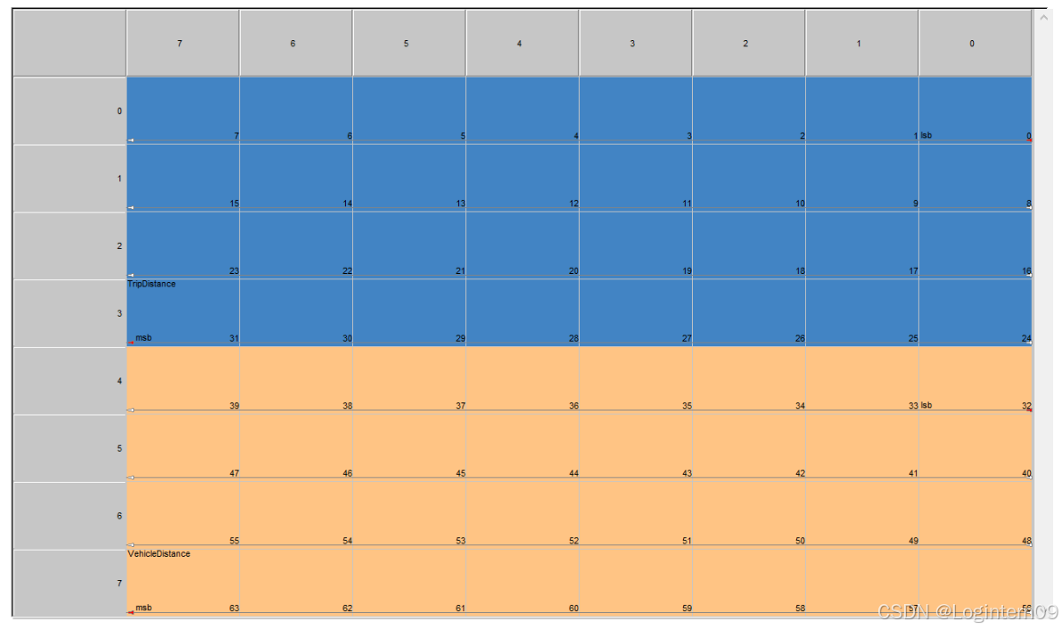
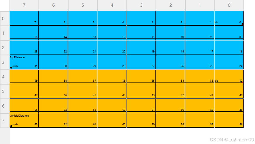
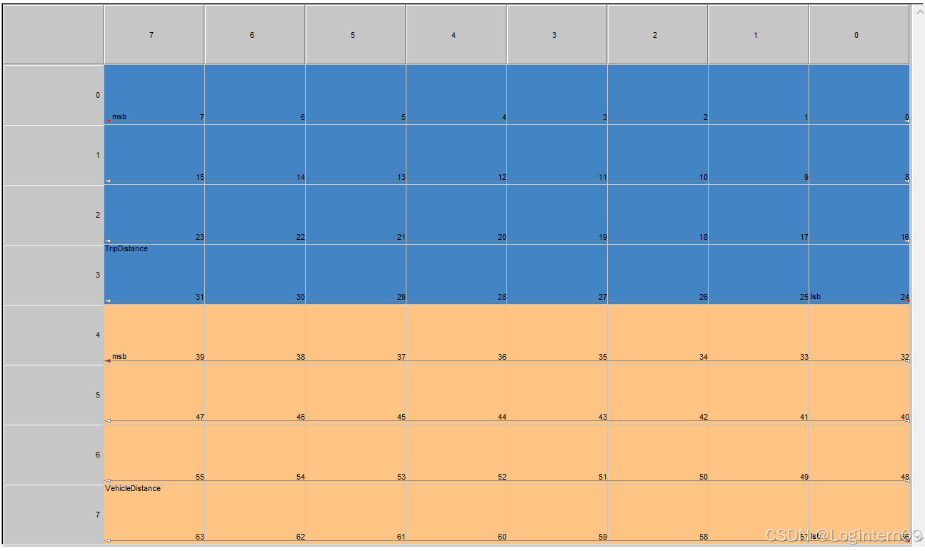
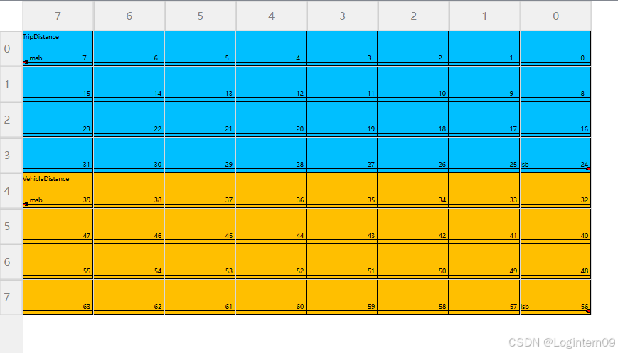
(1)针对信号是小端模式(Intel)的字节顺序,要求箭头的大小端指向是正确的

signal_layout = {
            "TripDistance": {
                "start_row": 0,
                "start_col": 7,
                "end_row": 3,
                "end_col": 0,
                "is_little_endian": True,
                "color": "#00BFFF",  # 深天蓝色
            },
            "VehicleDistance": {
                "start_row": 4,
                "start_col": 7,
                "end_row": 7,
                "end_col": 0,
                "is_little_endian": True,
                "color": "#FFBF00",  # 黄橙色
            },
        }
CANAB++显示信号的排布如下:
PySide6实现的代码效果如下:
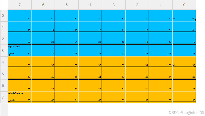
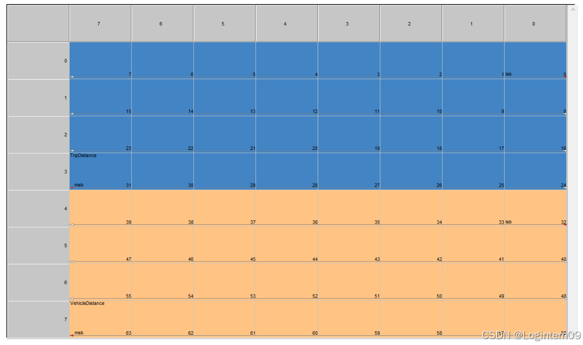
(2)针对信号是大端模式(Motorola)的字节顺序,要求箭头的大小端指向是正确的

signal_layout = {
            "TripDistance": {
                "start_row": 3,
                "start_col": 7,
                "end_row": 0,
                "end_col": 0,
                "is_little_endian": False,
                "color": "#00BFFF",  # 深天蓝色
            },
            "VehicleDistance": {
                "start_row": 7,
                "start_col": 7,
                "end_row": 4,
                "end_col": 0,
                "is_little_endian": False,
                "color": "#FFBF00",  # 黄橙色
            },
        }
CANAB++显示信号的排布如下:
PySide6实现的代码效果如下:
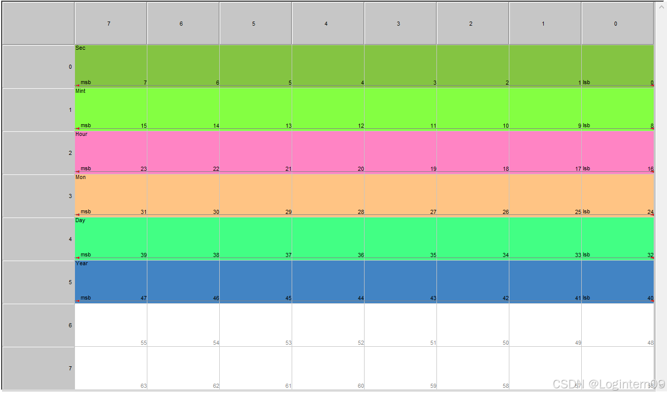
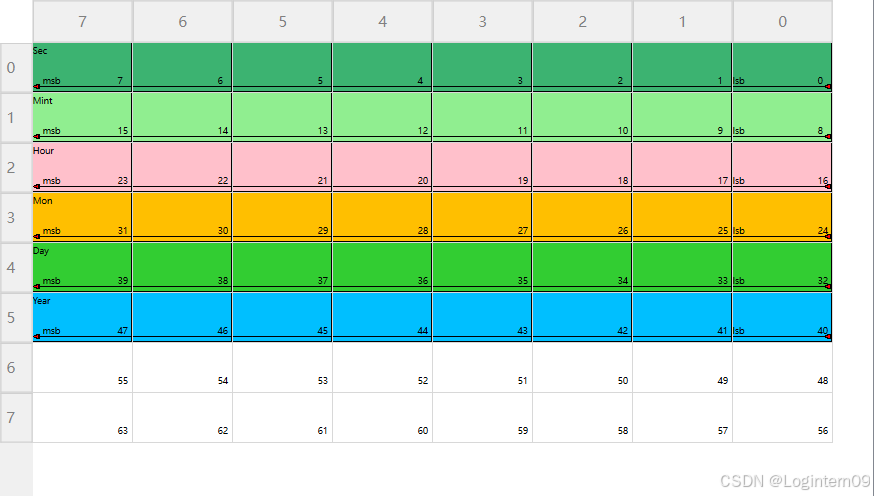
(3)字节顺序是Intel的多个信号,要求箭头的大小端指向是正确的
signal_layout = {
            "Sec": {
                "start_row": 0,
                "start_col": 7,
                "end_row": 0,
                "end_col": 0,
                "is_little_endian": True,
                "color": "#3CB371",  # 草绿色
            },
            "Mint": {
                "start_row": 1,
                "start_col": 7,
                "end_row": 1,
                "end_col": 0,
                "is_little_endian": True,
                "color": "#90EE90",  # 浅绿色
            },
            "Hour": {
                "start_row": 2,
                "start_col": 7,
                "end_row": 2,
                "end_col": 0,
                "is_little_endian": True,
                "color": "#FFC0CB",  # 桃红色
            },
            "Mon": {
                "start_row": 3,
                "start_col": 7,
                "end_row": 3,
                "end_col": 0,
                "is_little_endian": True,
                "color": "#FFBF00",  # 黄橙色
            },
            "Day": {
                "start_row": 4,
                "start_col": 7,
                "end_row": 4,
                "end_col": 0,
                "is_little_endian": True,
                "color": "#32CD32",  # 亮绿色
            },
            "Year": {
                "start_row": 5,
                "start_col": 7,
                "end_row": 5,
                "end_col": 0,
                "is_little_endian": True,
                "color": "#00BFFF",  # 深天蓝色
            },
        }
CANAB++显示信号的排布如下:
PySide6实现的代码效果如下:
(4)其他信号排布情况,待测试和优化代码。
5. 完整程序代码
#!/usr/bin/env python
# -*- coding: utf-8 -*-
# @Author : Logintern09

from PySide6.QtWidgets import (
    QApplication,
    QTableWidget,
    QTableWidgetItem,
    QStyledItemDelegate,
)
from PySide6.QtGui import QColor, QPolygonF, QPen, QBrush, QFont
from PySide6.QtCore import Qt, QRect, QPointF


class ArrowDelegate(QStyledItemDelegate):
    def __init__(self, signal_layout, table_widget, parent=None):
        super().__init__(parent)
        self.signal_layout = signal_layout
        self.table_widget = table_widget

        self._ini_variable()

    def _ini_variable(self):
        (
            self.start_cell_indexs,
            self.end_cell_indexs,
            self.signal_name_lst,
            self.signal_color_lst,
        ) = self._collect_signal_cell()
        self.middle_cell_indexs = self._collect_middle_cell_indexs()
        self.signal_color_cell_indexs = self._collect_signal_color_cell()

    def _get_cell_indices_between(
        self, start_row, start_col, end_row, end_col, is_little_endian
    ):
        cell_indices = []
        if is_little_endian:
            # 小端模式
            total_col_indexs = list(range(self.table_widget.columnCount()))
            if start_row == end_row:
                if end_col < start_col:
                    for col in range(start_col - 1, end_col, -1):
                        cell_indices.append(
                            self.table_widget.model().index(start_row, col)
                        )
            elif end_row > start_row:
                for row in range(start_row + 1, end_row):
                    for col in total_col_indexs:
                        cell_indices.append(self.table_widget.model().index(row, col))
                for col in range(start_col - 1, -1, -1):
                    cell_indices.append(self.table_widget.model().index(start_row, col))
                for col in range(end_col + 1, self.table_widget.columnCount()):
                    cell_indices.append(self.table_widget.model().index(end_row, col))
        else:
            # 大端模式
            total_col_indexs = list(range(self.table_widget.columnCount()))
            if start_row == end_row:
                if start_col > end_col:
                    for col in range(start_col - 1, end_col, -1):
                        cell_indices.append(
                            self.table_widget.model().index(start_row, col)
                        )
            elif end_row < start_row:
                for row in range(start_row - 1, end_row, -1):
                    for col in total_col_indexs:
                        cell_indices.append(self.table_widget.model().index(row, col))
                for col in range(start_col - 1, -1, -1):
                    cell_indices.append(self.table_widget.model().index(start_row, col))
                for col in range(self.table_widget.columnCount(), end_col, -1):
                    cell_indices.append(self.table_widget.model().index(end_row, col))
        return cell_indices

    def _collect_signal_cell(self):
        start_cell_indexs = []
        end_cell_indexs = []
        arrow_direction_lst = []
        signal_name_lst = []
        signal_color_lst = []
        for signal_name, layout_rule in self.signal_layout.items():
            start_row = layout_rule["start_row"]
            start_col = layout_rule["start_col"]
            end_row = layout_rule["end_row"]
            end_col = layout_rule["end_col"]
            start_cell_index = self.table_widget.model().index(start_row, start_col)
            end_cell_index = self.table_widget.model().index(end_row, end_col)
            start_cell_indexs.append(start_cell_index)
            end_cell_indexs.append(end_cell_index)
            signal_name_lst.append(signal_name)
            signal_color_lst.append(layout_rule["color"])
        return (
            start_cell_indexs,
            end_cell_indexs,
            signal_name_lst,
            signal_color_lst,
        )

    def _collect_middle_cell_indexs(self):
        middle_cell_indexs = []
        for signal_name, layout_rule in self.signal_layout.items():
            start_row = layout_rule["start_row"]
            start_col = layout_rule["start_col"]
            end_row = layout_rule["end_row"]
            end_col = layout_rule["end_col"]
            is_little_endian = layout_rule["is_little_endian"]
            middle_cell_indexs.extend(
                self._get_cell_indices_between(
                    start_row, start_col, end_row, end_col, is_little_endian
                )
            )
        return middle_cell_indexs

    def _collect_signal_color_cell(self):
        signal_color_cell_indexs = []
        for signal_name, layout_rule in self.signal_layout.items():
            start_row = layout_rule["start_row"]
            start_col = layout_rule["start_col"]
            end_row = layout_rule["end_row"]
            end_col = layout_rule["end_col"]
            is_little_endian = layout_rule["is_little_endian"]
            start_cell_index = self.table_widget.model().index(start_row, start_col)
            end_cell_index = self.table_widget.model().index(end_row, end_col)
            middle_cell_indexs = self._get_cell_indices_between(
                start_row, start_col, end_row, end_col, is_little_endian
            )
            signal_color_cell_indexs.append(
                [start_cell_index] + middle_cell_indexs + [end_cell_index]
            )
        return signal_color_cell_indexs

    def paint(self, painter, option, index):
        for signal_idx, signal_color_cell_lst in enumerate(
            self.signal_color_cell_indexs
        ):
            if index in signal_color_cell_lst:
                color = self.signal_color_lst[signal_idx]
                self._draw_signal_color(painter, option, color)

        # 绘制表征单元格所在报文排布的数字
        self._draw_cell_num(painter, option, index)

        if index in self.start_cell_indexs:
            arrow_direction = Qt.LeftArrow
            byte_order = "lsb"
            self._draw_start_arrow(painter, option, arrow_direction)
            self._draw_start_text(painter, option, byte_order)
        elif index in self.end_cell_indexs:
            signal_idx = self.end_cell_indexs.index(index)
            sinal_name = self.signal_name_lst[signal_idx]
            arrow_direction = Qt.LeftArrow
            byte_order = "msb"
            self._draw_end_arrow(painter, option, arrow_direction)
            self._draw_end_text(painter, option, sinal_name, byte_order)
        else:
            if index in self.middle_cell_indexs:
                self._draw_line(painter, option)
            else:
                # 为其他单元格使用默认绘制
                super().paint(painter, option, index)

    def _draw_signal_color(self, painter, option, color):
        # 创建一个 QBrush 对象
        brush = QBrush(color)
        # 使用 QPainter 的 setBrush 方法来设置填充颜色
        painter.setBrush(brush)
        # 绘制单元格的背景
        painter.drawRect(option.rect)

    def _draw_start_arrow(self, painter, option, arrow_direction):
        # 获取目标单元格的矩形区域
        cell_rect = option.rect

        # Define the arrow properties
        arrow_line_color = QColor(0, 0, 0)  # Black color for the line
        line_thickness = 1  # Thickness of the line

        # 计算直线和箭头的位置
        line_y_pos = (
            cell_rect.bottom() - line_thickness - 2
        )  # 2 pixels above the bottom
        line_start_x = cell_rect.left()
        line_end_x = cell_rect.right()

        # 绘制黑色的直线
        pen = QPen(arrow_line_color, line_thickness)
        painter.setPen(pen)
        painter.drawLine(
            QPointF(line_start_x, line_y_pos), QPointF(line_end_x, line_y_pos)
        )

        # 绘制红色的箭头
        arrow_color = QColor(255, 0, 0)  # Red color for the arrow
        arrow_size = 5  # Size of the arrowhead
        if arrow_direction == Qt.RightArrow:
            arrow_start_x = cell_rect.left()
            arrow_y_pos = (
                cell_rect.bottom() - line_thickness - 2
            )  # 2 pixels above the bottom
            arrow_head_points = [
                QPointF(arrow_start_x, arrow_y_pos + arrow_size // 2),
                QPointF(arrow_start_x + arrow_size, arrow_y_pos),
                QPointF(arrow_start_x - arrow_size, arrow_y_pos - arrow_size // 2),
            ]
        elif arrow_direction == Qt.LeftArrow:
            arrow_start_x = cell_rect.right()
            arrow_y_pos = (
                cell_rect.bottom() - line_thickness - 2
            )  # 2 pixels above the bottom
            arrow_head_points = [
                QPointF(arrow_start_x, arrow_y_pos - arrow_size // 2),
                QPointF(arrow_start_x - arrow_size, line_y_pos),
                QPointF(arrow_start_x, arrow_y_pos + arrow_size // 2),
            ]
        # You can add more directions if needed (UpArrow, DownArrow)
        else:
            # Default to no arrow if direction is unknown
            arrow_head_points = []

        if arrow_head_points:
            polygon = QPolygonF(arrow_head_points)
            brush = QBrush(arrow_color)
            painter.setBrush(brush)
            painter.drawPolygon(polygon)

    def _draw_end_arrow(self, painter, option, arrow_direction):
        # 获取目标单元格的矩形区域
        cell_rect = option.rect

        # Define the arrow properties
        arrow_line_color = QColor(0, 0, 0)  # Black color for the line
        line_thickness = 1  # Thickness of the line

        # 计算直线和箭头的位置
        line_y_pos = (
            cell_rect.bottom() - line_thickness - 2
        )  # 2 pixels above the bottom
        line_start_x = cell_rect.left()
        line_end_x = cell_rect.right()

        # 绘制黑色的直线
        pen = QPen(arrow_line_color, line_thickness)
        painter.setPen(pen)
        painter.drawLine(
            QPointF(line_start_x, line_y_pos), QPointF(line_end_x, line_y_pos)
        )

        # 绘制红色的箭头
        arrow_color = QColor(255, 0, 0)  # Red color for the arrow
        arrow_size = 5  # Size of the arrowhead
        if arrow_direction == Qt.RightArrow:
            arrow_start_x = cell_rect.right()
            arrow_y_pos = (
                cell_rect.bottom() - line_thickness - 2
            )  # 2 pixels above the bottom
            arrow_head_points = [
                QPointF(arrow_start_x, arrow_y_pos + arrow_size // 2),
                QPointF(arrow_start_x + arrow_size, arrow_y_pos),
                QPointF(arrow_start_x - arrow_size, arrow_y_pos - arrow_size // 2),
            ]
        elif arrow_direction == Qt.LeftArrow:
            arrow_start_x = cell_rect.left()
            arrow_y_pos = (
                cell_rect.bottom() - line_thickness - 2
            )  # 2 pixels above the bottom
            arrow_head_points = [
                QPointF(arrow_start_x + arrow_size, arrow_y_pos - arrow_size // 2),
                QPointF(arrow_start_x, line_y_pos),
                QPointF(arrow_start_x + arrow_size, arrow_y_pos + arrow_size // 2),
            ]
        # You can add more directions if needed (UpArrow, DownArrow)
        else:
            # Default to no arrow if direction is unknown
            arrow_head_points = []

        if arrow_head_points:
            polygon = QPolygonF(arrow_head_points)
            brush = QBrush(arrow_color)
            painter.setBrush(brush)
            painter.drawPolygon(polygon)

    def _draw_start_text(self, painter, option, byte_order):
        # 获取目标单元格的矩形区域
        cell_rect = option.rect

        # 设置文本颜色和字体(可选)
        painter.setPen(QPen(QColor(0, 0, 0)))  # 黑色文本
        font = QFont()
        font.setPointSize(5)  # 设置字体大小(可选)
        painter.setFont(font)

        # 计算文本的位置
        text_rect = QRect(
            cell_rect.left(),  # 文本左边缘与单元格左边缘对齐
            cell_rect.bottom()
            - 3
            - painter.fontMetrics().height(),  # 距离单元格底部3像素,并减去文本高度以确保文本不超出单元格
            cell_rect.width(),  # 文本宽度与单元格宽度相同(可以根据需要调整)
            painter.fontMetrics().height(),  # 文本高度
        )
        # 绘制文本
        painter.drawText(text_rect, Qt.AlignLeft | Qt.AlignVCenter, str(byte_order))

    def _draw_end_text(self, painter, option, sinal_name, byte_order):
        # 获取目标单元格的矩形区域
        cell_rect = option.rect

        # 设置文本颜色和字体(可选)
        painter.setPen(QPen(QColor(0, 0, 0)))  # 黑色文本
        font = QFont()
        font.setPointSize(5)  # 设置字体大小(可选)
        painter.setFont(font)

        # 计算文本的位置
        text_rect = QRect(
            cell_rect.left() + 8,  # 文本左边缘与单元格左边缘对齐
            cell_rect.bottom()
            - 3
            - painter.fontMetrics().height(),  # 距离单元格底部3像素,并减去文本高度以确保文本不超出单元格
            cell_rect.width(),  # 文本宽度与单元格宽度相同(可以根据需要调整)
            painter.fontMetrics().height(),  # 文本高度
        )
        # 绘制文本
        painter.drawText(text_rect, Qt.AlignLeft | Qt.AlignVCenter, str(byte_order))

        # 计算sinal_name的位置
        text_rect = QRect(
            cell_rect.left(),  # 文本左边缘与单元格左边缘对齐
            cell_rect.top() + 2,
            cell_rect.width(),  # 文本宽度与单元格宽度相同(可以根据需要调整)
            painter.fontMetrics().height(),  # 文本高度
        )
        painter.drawText(text_rect, Qt.AlignLeft | Qt.AlignVCenter, str(sinal_name))

    def _draw_line(self, painter, option):
        arrow_line_color = QColor(0, 0, 0)  # Black color for the line
        line_thickness = 1  # Thickness of the line

        # 获取目标单元格的矩形区域
        cell_rect = option.rect

        # 计算直线和箭头的位置
        line_y_pos = (
            cell_rect.bottom() - line_thickness - 2
        )  # 2 pixels above the bottom
        line_start_x = cell_rect.left()
        line_end_x = cell_rect.right()

        # 绘制黑色的直线
        pen = QPen(arrow_line_color, line_thickness)
        painter.setPen(pen)
        painter.drawLine(
            QPointF(line_start_x, line_y_pos), QPointF(line_end_x, line_y_pos)
        )

    def _draw_cell_num(self, painter, option, index):
        # 获取目标单元格的矩形区域
        cell_rect = option.rect

        # 设置文本颜色和字体(可选)
        painter.setPen(QPen(QColor(0, 0, 0)))  # 黑色文本
        font = QFont()
        font.setPointSize(5)  # 设置字体大小(可选)
        painter.setFont(font)

        # 计算文本的位置
        text_rect = QRect(
            cell_rect.right() - 10,
            cell_rect.bottom()
            - 3
            - painter.fontMetrics().height(),  # 距离单元格底部3像素,并减去文本高度以确保文本不超出单元格
            cell_rect.width(),  # 文本宽度与单元格宽度相同(可以根据需要调整)
            painter.fontMetrics().height(),  # 文本高度
        )
        # 绘制文本
        row = index.row()
        column = index.column()
        num = (row + 1) * 8 - column - 1
        painter.drawText(text_rect, Qt.AlignLeft | Qt.AlignVCenter, str(num))


class BasicTableWidget(QTableWidget):

    def __init__(self, parent=None):
        super(BasicTableWidget, self).__init__(parent)

        self.table_widget = QTableWidget(8, 8, self)
        self.table_widget.setFixedSize(700, 400)  # 设置固定大小
        self.table_widget.setHorizontalHeaderLabels([f"{i}" for i in range(7, -1, -1)])
        self.table_widget.setVerticalHeaderLabels([f"{i}" for i in range(8)])
        self._ini_table_style()

    def _ini_table_style(self):
        # self.table_widget.verticalHeader().hide()
        # self.table_widget.horizontalHeader().hide()
        self.set_cell_width()
        self.set_cell_height()
        # Set the selection mode to allow extended (multiple) selection
        self.table_widget.setSelectionMode(QTableWidget.ExtendedSelection)
        style_sheet = """
               QHeaderView::section {
                   background-color: #f0f0f0;  /* 可以设置背景色为浅灰色,如果需要的话 */
                   color: #808080;            /* 设置文字颜色为灰色 */
                   padding: 4px;              /* 可选:设置内边距 */
                   border: 1px solid #d0d0d0;  /* 可选:设置边框 */
               }
               """
        self.table_widget.setStyleSheet(style_sheet)

    def set_cell_range_background_color(
        self, start_row, start_col, end_row, end_col, color
    ):
        for row in range(start_row, end_row + 1):
            for col in range(start_col, end_col + 1):
                item = self.table_widget.item(row, col)
                if item is None:
                    item = QTableWidgetItem()
                    self.table_widget.setItem(row, col, item)
                item.setBackground(color)

    def set_cell_width(self):
        for col in range(self.table_widget.columnCount()):
            self.table_widget.setColumnWidth(col, 80)

    def set_cell_height(self):
        for row in range(self.table_widget.rowCount()):
            self.table_widget.setRowHeight(row, 40)

    def set_signal_cell_style(self, signal_layout):
        # 创建并设置自定义委托
        arrow_delegate = ArrowDelegate(signal_layout, self.table_widget)
        self.table_widget.setItemDelegate(arrow_delegate)


class QLayoutWidget(BasicTableWidget):

    def __init__(self, parent=None):
        super(QLayoutWidget, self).__init__(parent)
        self.setWindowFlags(self.windowFlags() | Qt.FramelessWindowHint)
        self.setAttribute(Qt.WA_TranslucentBackground)
        self.setFixedSize(700, 400)

        signal_layout = {
            "Sec": {
                "start_row": 0,
                "start_col": 7,
                "end_row": 0,
                "end_col": 0,
                "is_little_endian": True,
                "color": "#3CB371",  # 草绿色
            },
            "Mint": {
                "start_row": 1,
                "start_col": 7,
                "end_row": 1,
                "end_col": 0,
                "is_little_endian": True,
                "color": "#90EE90",  # 浅绿色
            },
            "Hour": {
                "start_row": 2,
                "start_col": 7,
                "end_row": 2,
                "end_col": 0,
                "is_little_endian": True,
                "color": "#FFC0CB",  # 桃红色
            },
            "Mon": {
                "start_row": 3,
                "start_col": 7,
                "end_row": 3,
                "end_col": 0,
                "is_little_endian": True,
                "color": "#FFBF00",  # 黄橙色
            },
            "Day": {
                "start_row": 4,
                "start_col": 7,
                "end_row": 4,
                "end_col": 0,
                "is_little_endian": True,
                "color": "#32CD32",  # 亮绿色
            },
            "Year": {
                "start_row": 5,
                "start_col": 7,
                "end_row": 5,
                "end_col": 0,
                "is_little_endian": True,
                "color": "#00BFFF",  # 深天蓝色
            },
        }

        self.set_signal_cell_style(signal_layout)


if __name__ == "__main__":
    app = QApplication([])
    widget = QLayoutWidget()
    widget.show()
    app.exec()


 被折叠的 条评论
为什么被折叠?
被折叠的 条评论
为什么被折叠?
 到【灌水乐园】发言


