


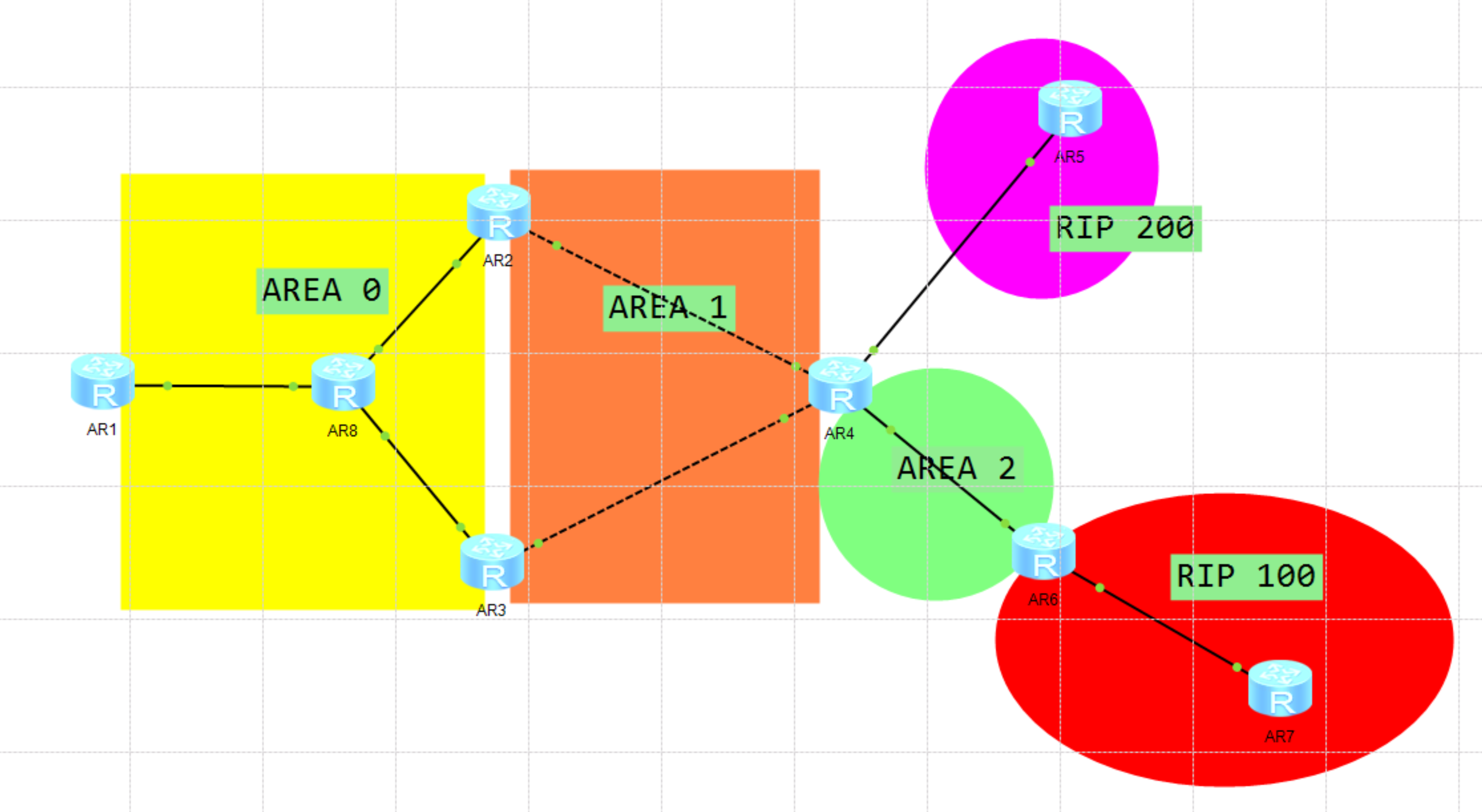
要求: 1.如图连接,合理规划IP地址,所有路由器各自创建一个loopback接口 2.R1再创建三个接口IP地址为201.1.1.1/24、201.1.2.1/24、201.1.3.1/24 R5再创建三个接口IP地址为202.1.1.1/24、202.1.2.1/24、202.1.3.1/24 R7再创建三个接口IP地址为203.1.1.1/24、203.1.2.1/24、203.1.3.1/24 3.如图运行路由协议 R1 -R2 -R3之间使用MGRE网络,为hub-spoke 网络结构,R1为hub端 , 部署OSPF网络,MGRE修改为BMA网络类型 4.area 1 区域不得出现4.5类LSA 5.其他区域优先通过R3访问R1 三个环回接口 6.尽量减少路由条目数量 7.area 1 区域增加安全性 8.全网可达
R1
R2
sys
sys r2
user-interface console 0
idle-timeout 0 0
int lo0
ip add 2.2.2.2 24
int g 0/0/0
ip add 28.1.1.1 24
int s4/0/0
ip add 24.1.1.1 24
R3
sys
sys r3
user-interface console 0
idle-timeout 0 0
int lo0
ip add 3.3.3.3 24
int g 0/0/0
ip add 38.1.1.1 24
int s4/0/0
ip add 34.1.1.1 24
R4
sys
sys r4
user-interface console 0
idle-timeout 0 0
int lo0
ip add 4.4.4.4 24
int s4/0/0
ip add 24.1.1.2 24
int s4/0/1
ip add 34.1.1.2 24
int g0/0/0
ip add 45.1.1.1 24
int g0/0/2
ip add 46.1.1.1 24
R5
sys r5
user-interface console 0
idle-timeout 0 0
int lo0
ip add 5.5.5.5 24
ip add 45.1.1.2 24
R6
sys r6
user-interface console 0
idle-timeout 0 0
int lo0
ip add 6.6.6.6 24
int g0/0/2
ip add 46.1.1.2 24
int g0/0/0
ip add 67.1.1.1 24
R7
sys r7
user-interface console 0
idle-timeout 0 0
int lo0
ip add 7.7.7.7 24
ip add 67.1.1.2 24
R8
sys isp
user-interface console 0
idle-timeout 0 0
int g0/0/0
ip add 18.1.1.2 24
int g0/0/1
ip add 28.1.1.2 24
int g 0/0/2
ip add 38.1.1.2 24
dis ip int bri
ping 18.1.1.1
ping 28.1.1.1
ping 38.1.1.1
[r6]ping 67.1.1.2
[r4]dis ip int bri
ping 24.1.1.1
ping 34.1.1.1
ping 45.1.1.2
ping 46.1.1.2
[r1]
ip route-s 0.0.0.0 0 18.1.1.2
ping 28.1.1.1
ping 38.1.1.1
int t0/0/0
ip address 100.1.1.1 24
tunnel-protocol gre p2mp
tunnel-protocol s
source 18.1.1.1
nhrp network-id 100
nhrp entry multicast dynamic
dis this
[r2]
ip route-s 0.0.0.0 0 28.1.1.2
int t 0/0/0
ip add 100.1.1.2 24
tunnel-protocol gre p2mp
source 28.1.1.1
nhrp network-id 100
nhrp entry 100.1.1.1 18.1.1.1 register
dis this
[r3]
ip route-s 0.0.0.0 0 38.1.1.2
int t 0/0/0
ip add 100.1.1.3 24
tunnel-protocol gre p2mp
source 3 8.1.1.1
nhrp network-id 100
nhrp entry 100.1.1.1 18.1.1.1 register
dis this
R1再创建三个接口IP地址为201.1.1.1/24、201.1.2.1/24、201.1.3.1/24 R5再创建三个接口IP地址为202.1.1.1/24、202.1.2.1/24、202.1.3.1/24 R7再创建三个接口IP地址为203.1.1.1/24、203.1.2.1/24、203.1.3.1/24
[r1]
int l 1
ip add 201.1.1.1 24
int l 2
ip add 201.1.2.1 24
int l 3
ip add 201.1.3.1 24
[r5]
int l 1
ip add 202.1.1.1 24
int l 2
ip add 202.1.2.1 24
int l 3
ip add 203.1.3.1 24
[r7]
int l 1
ip add 203.1.1.1 24
int l 2
ip add 203.1.2.1 24
int l 3
ip add 203.1.3.1 24
3.如图运行路由协议 R1 -R2 -R3之间使用MGRE网络,为hub-spoke 网络结构,R1为hub端 , 部署OSPF网络,MGRE修改为BMA网络类型
[r1]
ospf 100 router-is 91.1.1.1
area 0
network 1.1.1.1 0.0.0.0
network 201.1.0.0 0.0.255.255
network 100.1.1.1 0.0.0.0
int lo0
ospf network-type broadcast
in lo1
ospf network-type broadcast
in lo2
ospf network-type broadcast
in lo3
ospf network-type broadcast
[r2]
ospf 100 router-is 92.2.2.2
area 0
network 100.1.1.2 0.0.0.0
q
area 1
network 24.1.1.2 0.0.0.0
network 2.2.2.2 0.0.0.0
int lo0
ospf network-type broadcast
[r3]
ospf 100 router-is 93.3.3.3
area 0
network 100.1.1.3 0.0.0.0
q
area 1
network 34.1.1.2 0.0.0.0
network 3.3.3.3 0.0.0.0
int lo0
ospf network-type broadcast
[r4]
ospf 100 router-is 94.4.4.4
area 1
network 4.4.4.4 0.0.0.0
network 24.1.1.2 0.0.0.0
network 34.1.1.2 0.0.0.0
area 2
network 46.1.1.1 0.0.0.0
int lo0
ospf network-type broadcast
rip 200
ver 2
network 45.0.0.0
[r5]
rip 200
ver 2
network 5.0.0.0
network 45.0.0.0
network 202.1.1.0
network 202.1.2.0
network 202.1.3.0
[r6]
ospf 100 router-is 96.6.6.6
area 2
network 46.1.1.2 0.0.0.0
network 6.6.6.6 0.0.0.0
int lo0
ospf network-type broadcast
rip 100
ver 2
network 67.0.0.0
[r7]
rip 100
ver 2
network 67.0.0.0
network 7.0.0.0
network 203.1.1.0
network 203.1.2.0
network 203.1.3.0


 102
102


 被折叠的 条评论
为什么被折叠?
被折叠的 条评论
为什么被折叠?
 到【灌水乐园】发言


