


目录
1.新建工程
本博客以官方给的sysconfig空模板为基础,做简单修改后即可实现点灯
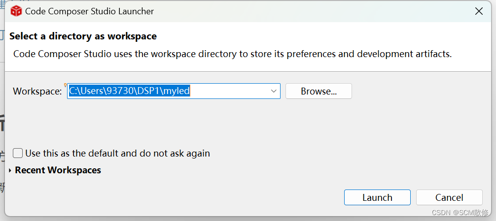
首先在自己想要的位置新建文件夹作为ccs工作环境,之后打开CCS,在WorkSpace中选择该文件夹作为工作环境,点击Launch
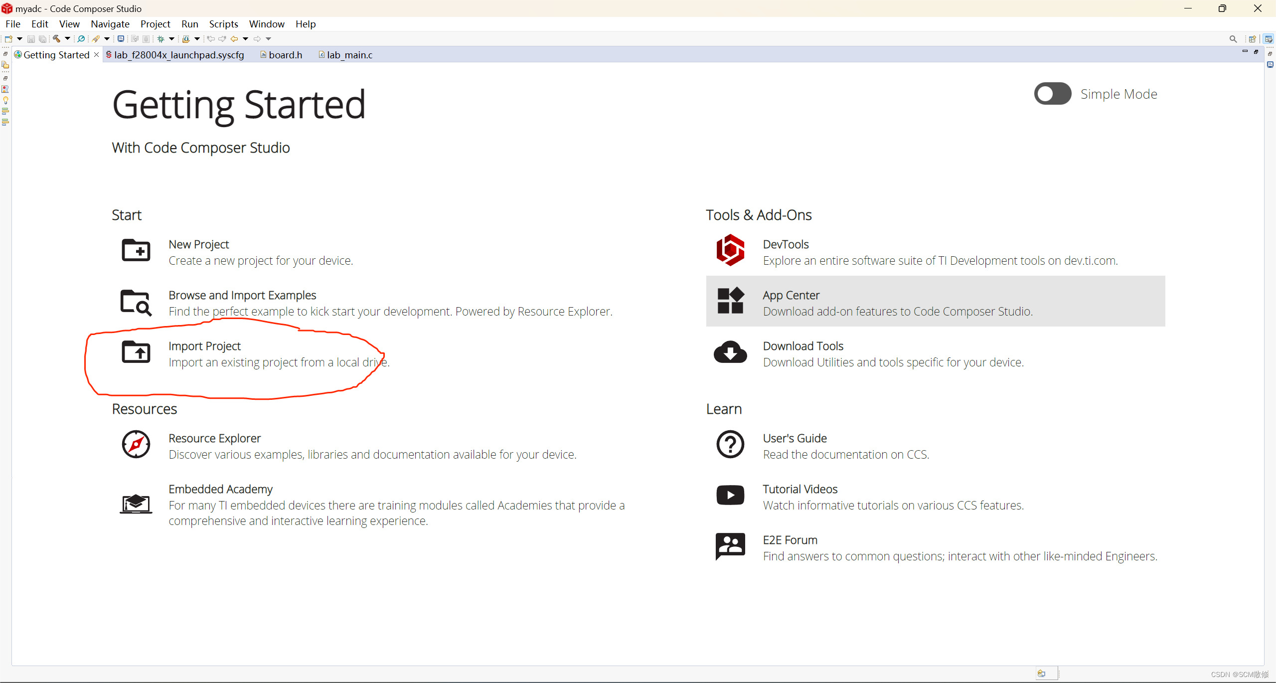
之后用户会看到如下界面:
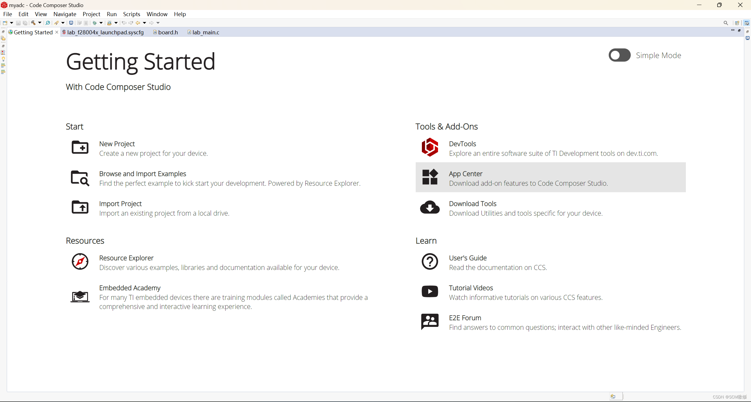
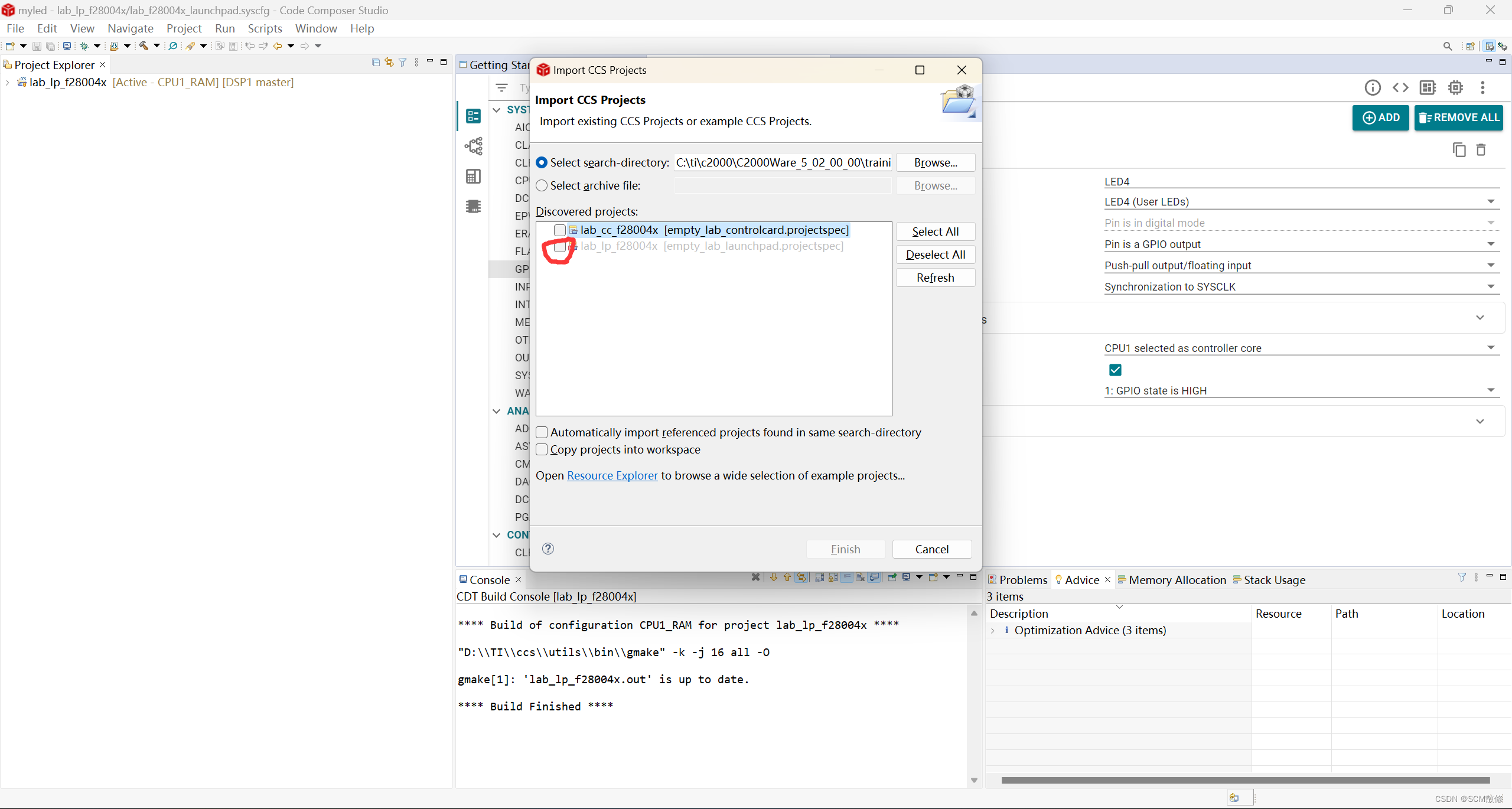
点击import project->Browse开始导入sysconfig模板
PS:import project也可从上方菜单栏project->import project中打开
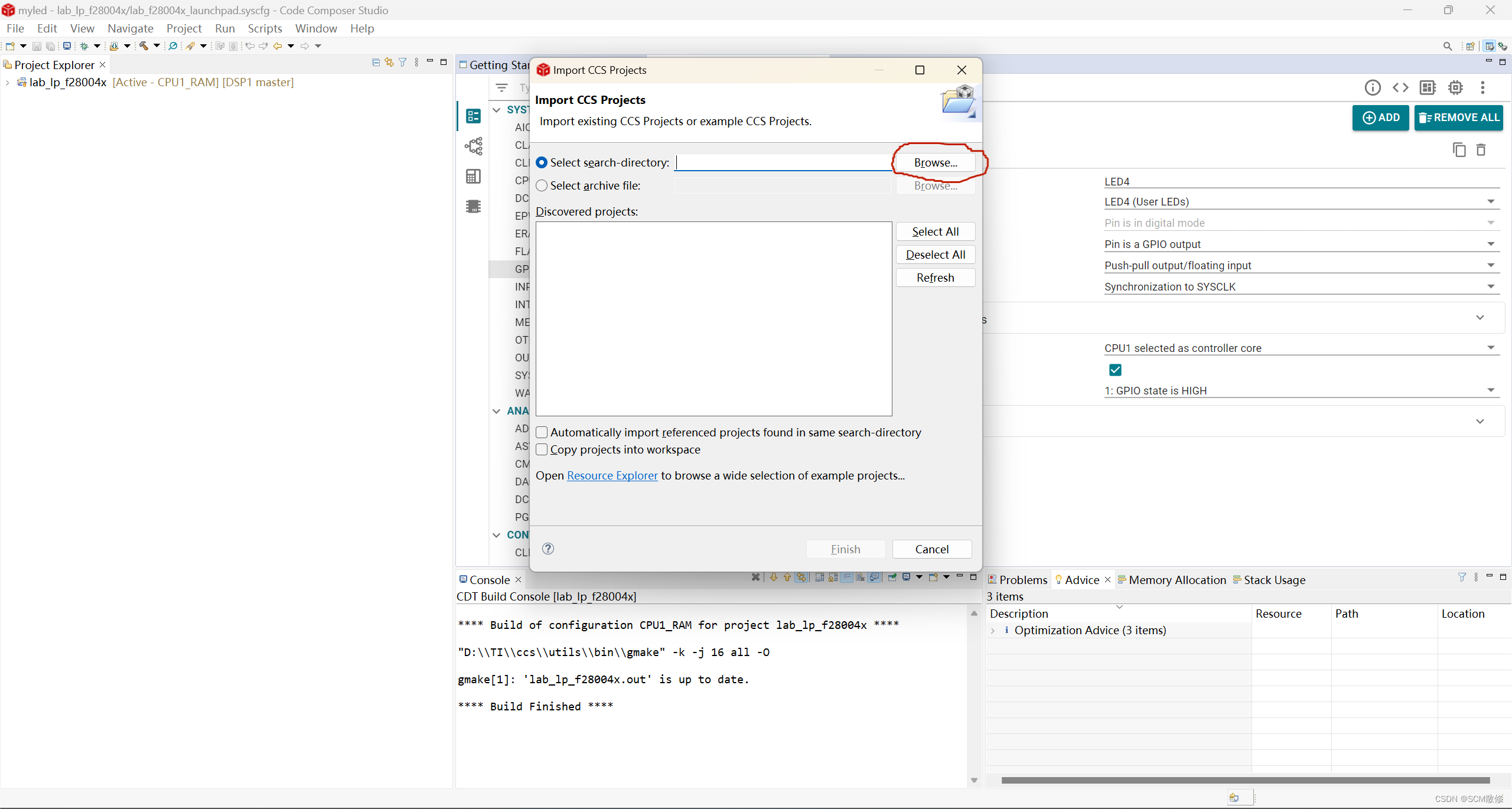
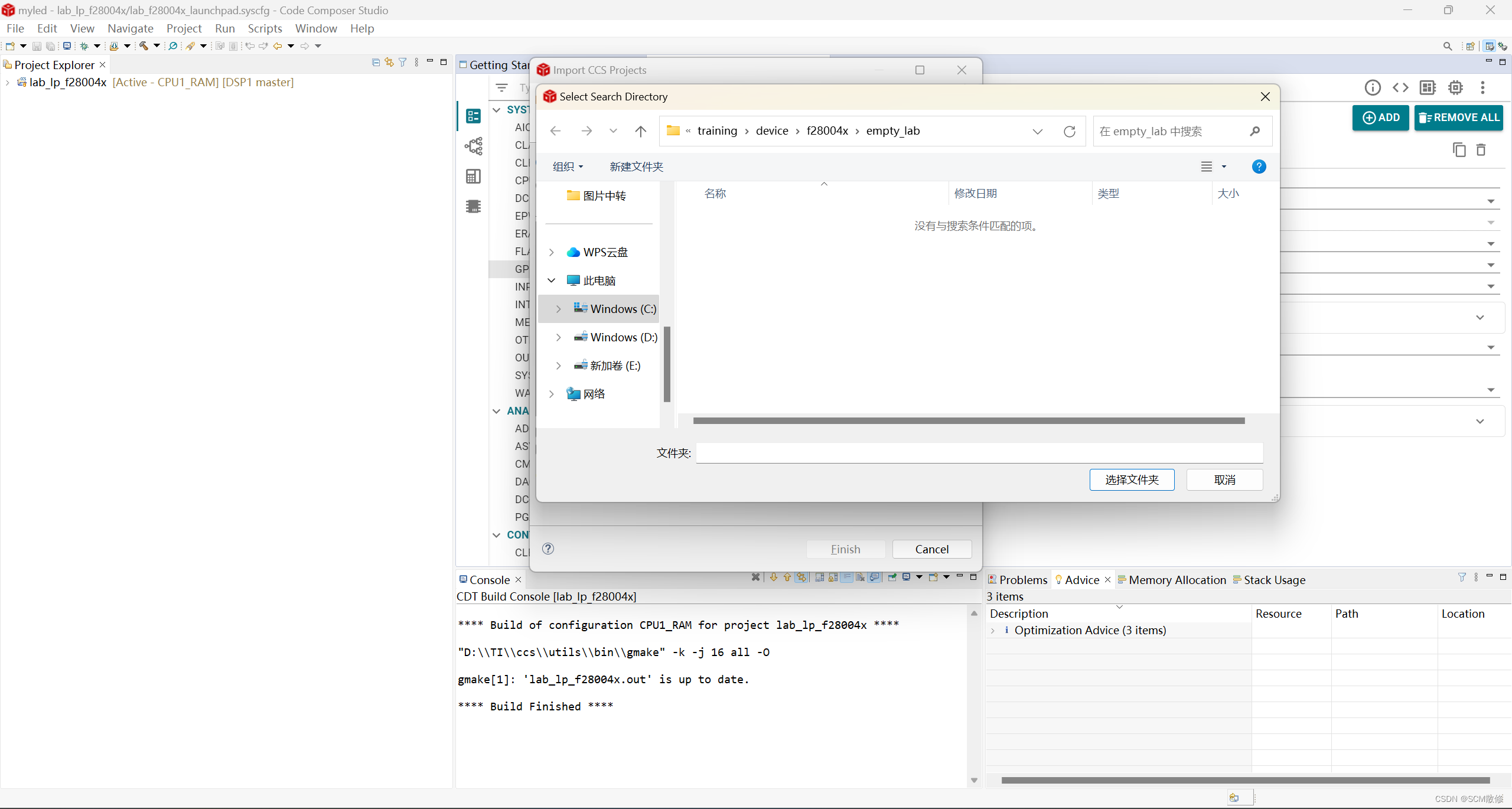
在弹出的Select Search Directory中选择如下路径
C:\ti\c2000\C2000Ware_5_02_00_00\training\device\f28004x\empty_lab
该路径会根据用户安装C2000ware的位置改变
在之后弹出的对话框中勾选lab_lp,并点击finish即可引入成功
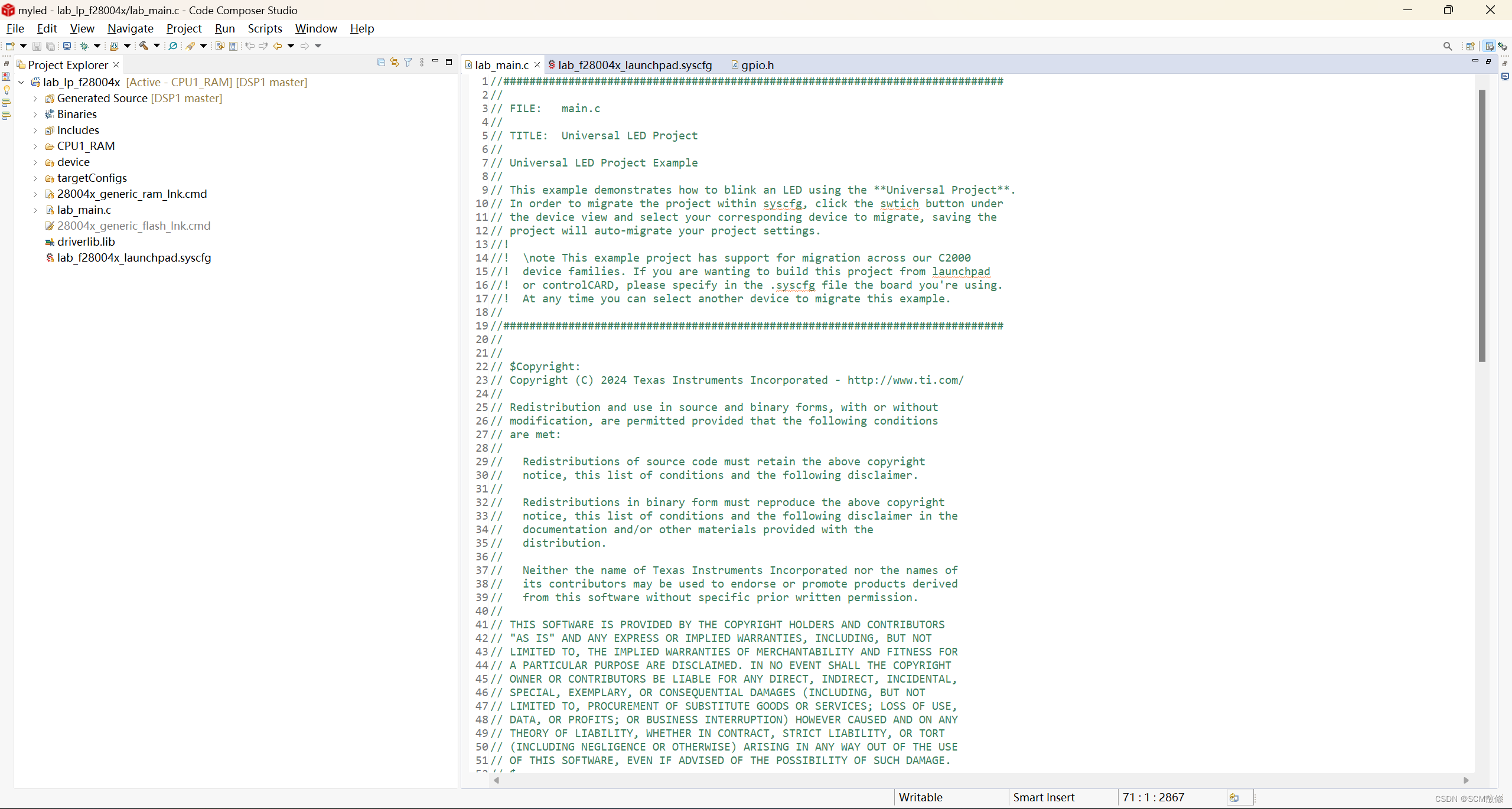
展开左边Project_Explorer栏中工程,可看到如下文件
PS:若不慎关闭Project_Explorer,可在View->Project_Explorer中再次打开
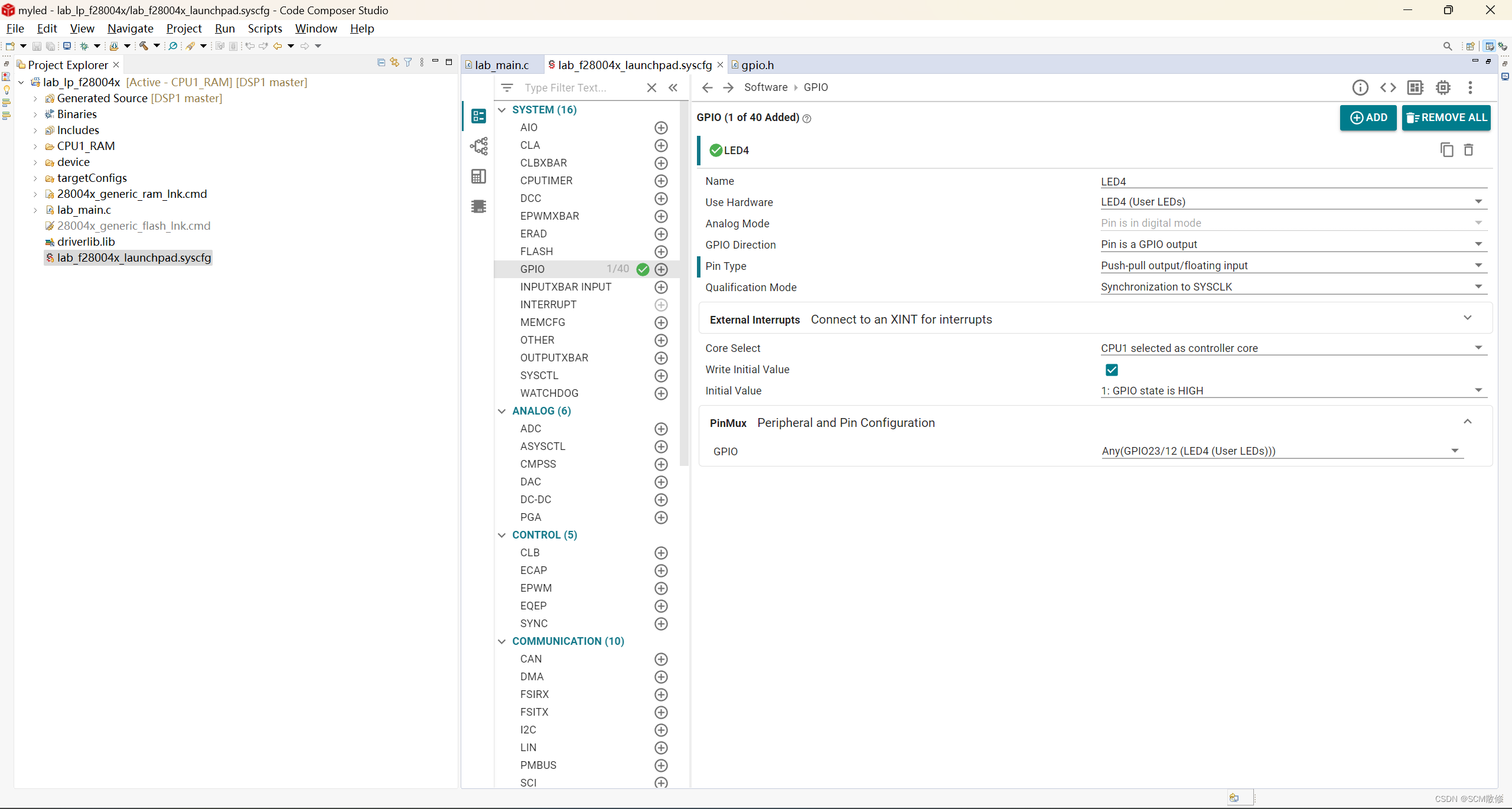
之后点击左侧.syscfg后缀的文件即可进入时钟树配置
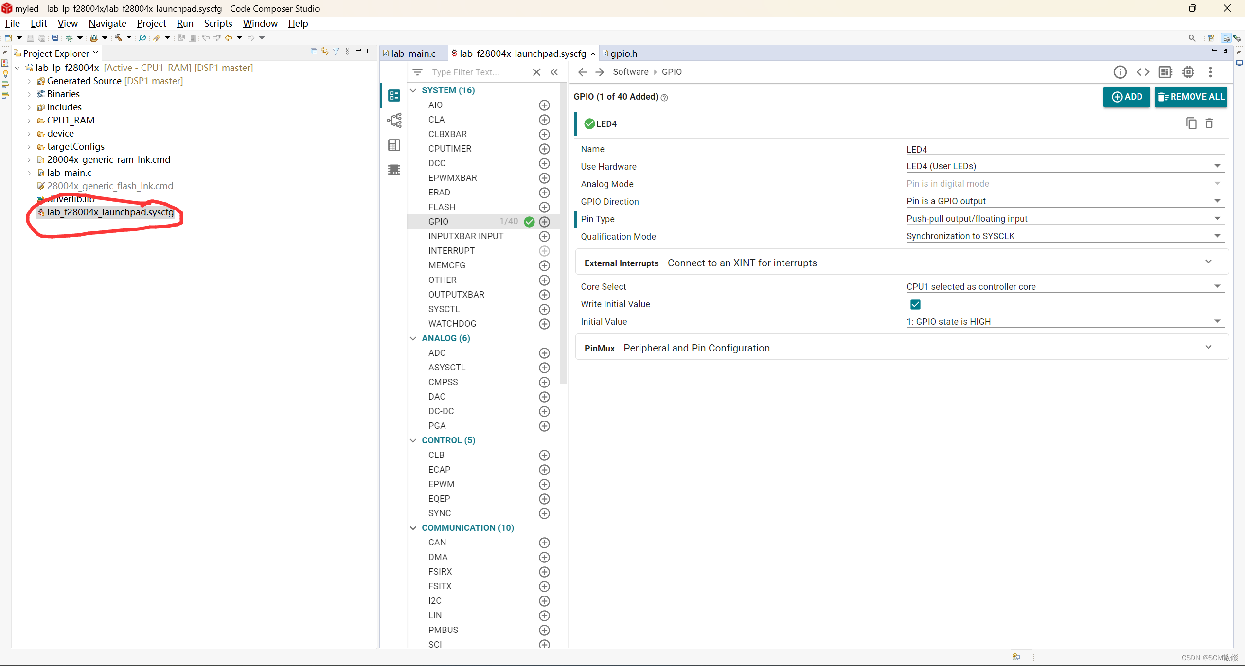
这里我们只用到了LED,故在SYSTEM中添加一个GPIO即可(上图中点击GPIO后的加号),并按照下图配置GPIO,按下Ctrl+S保存
PS:这里的LED有LED4(GPIO23)和LED5(GPIO34)两个灯,在PinMux栏中可以选择任意一个配置
之后点击Project->Build All编译工程即可在左边Project_Explorer栏中看到Generated Source中生成的头文件
新建工程完毕,接下来开始点灯
-------------------------------------------------------------------------------------------------------------------------------
2.点灯
2.1代码编写
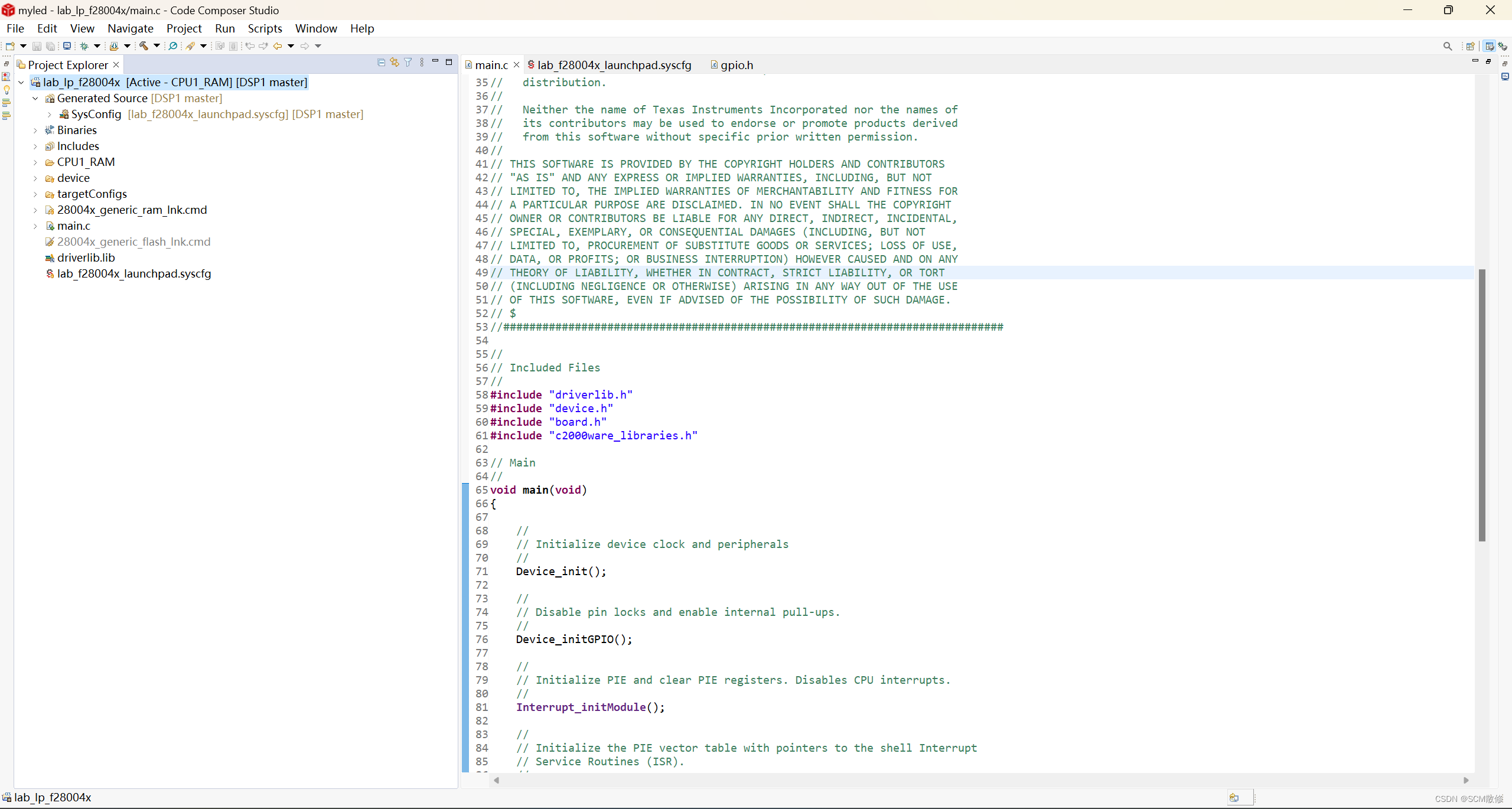
在左边Project_Explorer栏中打开lab_main.c,这是工程的main.c文件,建议大家右键此文件,选择Rename,将文件名改为main.c,然后就可以开始点灯了
//#############################################################################
//
// FILE:   main.c
//
// TITLE:  Universal LED Project
//
// Universal LED Project Example
//
// This example demonstrates how to blink an LED using the **Universal Project**.
// In order to migrate the project within syscfg, click the swtich button under
// the device view and select your corresponding device to migrate, saving the
// project will auto-migrate your project settings.
//!
//!  \note This example project has support for migration across our C2000
//!  device families. If you are wanting to build this project from launchpad
//!  or controlCARD, please specify in the .syscfg file the board you're using.
//!  At any time you can select another device to migrate this example.
//
//#############################################################################
//
//
// $Copyright:
// Copyright (C) 2024 Texas Instruments Incorporated - http://www.ti.com/
//
// Redistribution and use in source and binary forms, with or without
// modification, are permitted provided that the following conditions
// are met:
//
//   Redistributions of source code must retain the above copyright
//   notice, this list of conditions and the following disclaimer.
//
//   Redistributions in binary form must reproduce the above copyright
//   notice, this list of conditions and the following disclaimer in the
//   documentation and/or other materials provided with the
//   distribution.
//
//   Neither the name of Texas Instruments Incorporated nor the names of
//   its contributors may be used to endorse or promote products derived
//   from this software without specific prior written permission.
//
// THIS SOFTWARE IS PROVIDED BY THE COPYRIGHT HOLDERS AND CONTRIBUTORS
// "AS IS" AND ANY EXPRESS OR IMPLIED WARRANTIES, INCLUDING, BUT NOT
// LIMITED TO, THE IMPLIED WARRANTIES OF MERCHANTABILITY AND FITNESS FOR
// A PARTICULAR PURPOSE ARE DISCLAIMED. IN NO EVENT SHALL THE COPYRIGHT
// OWNER OR CONTRIBUTORS BE LIABLE FOR ANY DIRECT, INDIRECT, INCIDENTAL,
// SPECIAL, EXEMPLARY, OR CONSEQUENTIAL DAMAGES (INCLUDING, BUT NOT
// LIMITED TO, PROCUREMENT OF SUBSTITUTE GOODS OR SERVICES; LOSS OF USE,
// DATA, OR PROFITS; OR BUSINESS INTERRUPTION) HOWEVER CAUSED AND ON ANY
// THEORY OF LIABILITY, WHETHER IN CONTRACT, STRICT LIABILITY, OR TORT
// (INCLUDING NEGLIGENCE OR OTHERWISE) ARISING IN ANY WAY OUT OF THE USE
// OF THIS SOFTWARE, EVEN IF ADVISED OF THE POSSIBILITY OF SUCH DAMAGE.
// $
//#############################################################################

//
// Included Files
//
#include "driverlib.h"
#include "device.h"
#include "board.h"
#include "c2000ware_libraries.h"

// Main
//
void main(void)
{

    //
    // Initialize device clock and peripherals
    //
    Device_init();

    //
    // Disable pin locks and enable internal pull-ups.
    //
    Device_initGPIO();

    //
    // Initialize PIE and clear PIE registers. Disables CPU interrupts.
    //
    Interrupt_initModule();

    //
    // Initialize the PIE vector table with pointers to the shell Interrupt
    // Service Routines (ISR).
    //
    Interrupt_initVectorTable();

    //
    // PinMux and Peripheral Initialization
    //
    Board_init();

    //
    // C2000Ware Library initialization
    //
    C2000Ware_libraries_init();

    //
    // Enable Global Interrupt (INTM) and real time interrupt (DBGM)
    //
    EINT;
    ERTM;

    //
    // Loop Forever
    //
    for(;;)
    {
        //
        // toggle on LED
        //
        GPIO_togglePin(LED4);

        //
        // Delay for a bit.
        //
        DEVICE_DELAY_US(500000);
    }
}

//
// End of File
//
复制如下代码到main.c中即可,此文件中的配置作为main.c固定模板即可
2.2调试器配置
之后右键左边菜单栏自己的工程文件(下图蓝色部分)
选择Properties,即可打开如下界面
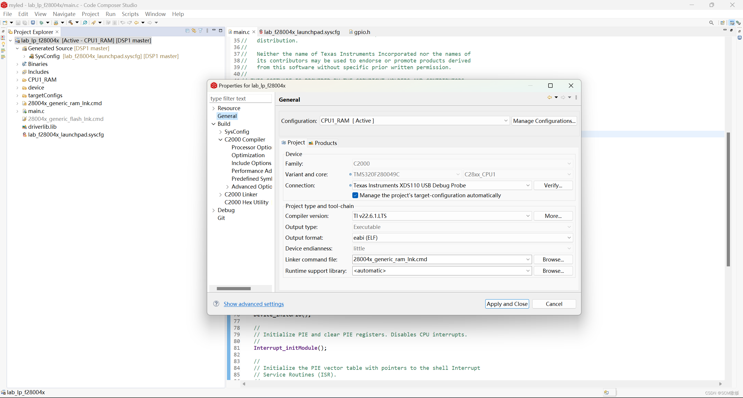
在General栏中的Connection中选择自己的Debug调试器,我的是XDS110 USB
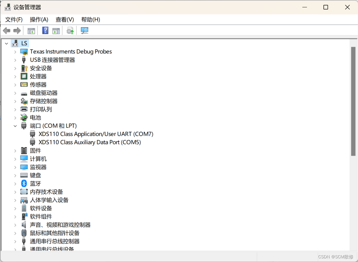
自己的调试器型号可以在设备管理器->端口中查看(注意要插上板子再看)
然后在上方菜单栏中点击Run->Debug就可以进入调试模式并检测到自己的DSP了,然后点击上方的红色停止间退出调试模式(如图)
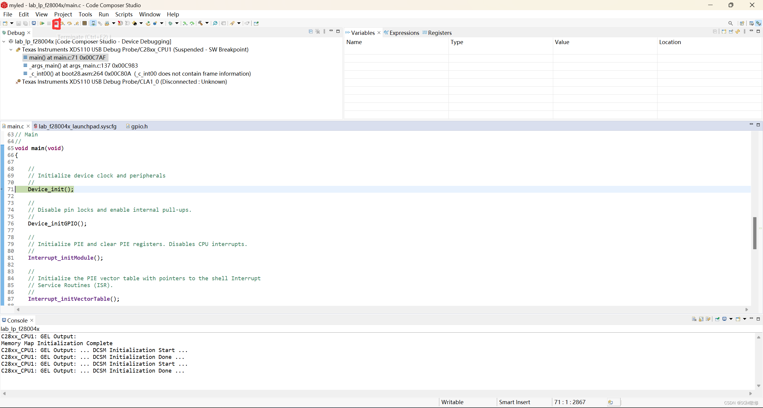
再点击Run->Load->lab_lp_f28004x(自己的工程名)即可成功烧录,就可以看到LED在闪烁了
3.代码分析(main.c详解)
main.c中总共包含了四个头文件
#include "driverlib.h"
#include "device.h"
#include "board.h"
#include "c2000ware_libraries.h"
3.1driverlib.h及库函数解析
driverlib.h中定义了我们全部的库函数,可以右键->Open Declaration查看具体内容
//#############################################################################
//
// FILE:   driverlib.h
//
// TITLE:  C28x Driverlib Header File
//
//#############################################################################
//
//
// $Copyright:
// Copyright (C) 2024 Texas Instruments Incorporated - http://www.ti.com/
//
// Redistribution and use in source and binary forms, with or without
// modification, are permitted provided that the following conditions
// are met:
//
//   Redistributions of source code must retain the above copyright
//   notice, this list of conditions and the following disclaimer.
//
//   Redistributions in binary form must reproduce the above copyright
//   notice, this list of conditions and the following disclaimer in the
//   documentation and/or other materials provided with the
//   distribution.
//
//   Neither the name of Texas Instruments Incorporated nor the names of
//   its contributors may be used to endorse or promote products derived
//   from this software without specific prior written permission.
//
// THIS SOFTWARE IS PROVIDED BY THE COPYRIGHT HOLDERS AND CONTRIBUTORS
// "AS IS" AND ANY EXPRESS OR IMPLIED WARRANTIES, INCLUDING, BUT NOT
// LIMITED TO, THE IMPLIED WARRANTIES OF MERCHANTABILITY AND FITNESS FOR
// A PARTICULAR PURPOSE ARE DISCLAIMED. IN NO EVENT SHALL THE COPYRIGHT
// OWNER OR CONTRIBUTORS BE LIABLE FOR ANY DIRECT, INDIRECT, INCIDENTAL,
// SPECIAL, EXEMPLARY, OR CONSEQUENTIAL DAMAGES (INCLUDING, BUT NOT
// LIMITED TO, PROCUREMENT OF SUBSTITUTE GOODS OR SERVICES; LOSS OF USE,
// DATA, OR PROFITS; OR BUSINESS INTERRUPTION) HOWEVER CAUSED AND ON ANY
// THEORY OF LIABILITY, WHETHER IN CONTRACT, STRICT LIABILITY, OR TORT
// (INCLUDING NEGLIGENCE OR OTHERWISE) ARISING IN ANY WAY OUT OF THE USE
// OF THIS SOFTWARE, EVEN IF ADVISED OF THE POSSIBILITY OF SUCH DAMAGE.
// $
//#############################################################################
#ifndef DRIVERLIB_H
#define DRIVERLIB_H

#include "inc/hw_memmap.h"

#include "adc.h"
#include "asysctl.h"
#include "can.h"
#include "cla.h"
#include "clb.h"
#include "clapromcrc.h"
#include "cmpss.h"
#include "cpu.h"
#include "cputimer.h"
#include "dac.h"
#include "dcc.h"
#include "dcsm.h"
#include "debug.h"
#include "dma.h"
#include "ecap.h"
#include "epwm.h"
#include "eqep.h"
#include "erad.h"
#include "flash.h"
#include "fsi.h"
#include "gpio.h"
#include "hrcap.h"
#include "hrpwm.h"
#include "i2c.h"
#include "interrupt.h"
#include "lin.h"
#include "memcfg.h"
#include "pga.h"
#include "pin_map.h"
#include "pin_map_legacy.h"
#include "pmbus.h"
#include "sci.h"
#include "sdfm.h"
#include "spi.h"
#include "sysctl.h"
#include "version.h"
#include "xbar.h"

#include "driver_inclusive_terminology_mapping.h"

#endif  // end of DRIVERLIB_H definition
我们本次使用的Led调用的是gpio.h中的部分函数,同样打开gpio.h查看库函数
//###########################################################################
//
// FILE:   gpio.h
//
// TITLE:  C28x GPIO driver.
//
//###########################################################################
// $Copyright:
// Copyright (C) 2024 Texas Instruments Incorporated - http://www.ti.com/
//
// Redistribution and use in source and binary forms, with or without
// modification, are permitted provided that the following conditions
// are met:
//
//   Redistributions of source code must retain the above copyright
//   notice, this list of conditions and the following disclaimer.
//
//   Redistributions in binary form must reproduce the above copyright
//   notice, this list of conditions and the following disclaimer in the
//   documentation and/or other materials provided with the
//   distribution.
//
//   Neither the name of Texas Instruments Incorporated nor the names of
//   its contributors may be used to endorse or promote products derived
//   from this software without specific prior written permission.
//
// THIS SOFTWARE IS PROVIDED BY THE COPYRIGHT HOLDERS AND CONTRIBUTORS
// "AS IS" AND ANY EXPRESS OR IMPLIED WARRANTIES, INCLUDING, BUT NOT
// LIMITED TO, THE IMPLIED WARRANTIES OF MERCHANTABILITY AND FITNESS FOR
// A PARTICULAR PURPOSE ARE DISCLAIMED. IN NO EVENT SHALL THE COPYRIGHT
// OWNER OR CONTRIBUTORS BE LIABLE FOR ANY DIRECT, INDIRECT, INCIDENTAL,
// SPECIAL, EXEMPLARY, OR CONSEQUENTIAL DAMAGES (INCLUDING, BUT NOT
// LIMITED TO, PROCUREMENT OF SUBSTITUTE GOODS OR SERVICES; LOSS OF USE,
// DATA, OR PROFITS; OR BUSINESS INTERRUPTION) HOWEVER CAUSED AND ON ANY
// THEORY OF LIABILITY, WHETHER IN CONTRACT, STRICT LIABILITY, OR TORT
// (INCLUDING NEGLIGENCE OR OTHERWISE) ARISING IN ANY WAY OUT OF THE USE
// OF THIS SOFTWARE, EVEN IF ADVISED OF THE POSSIBILITY OF SUCH DAMAGE.
// $
//###########################################################################

#ifndef GPIO_H
#define GPIO_H

//*****************************************************************************
//
// If building with a C++ compiler, make all of the definitions in this header
// have a C binding.
//
//*****************************************************************************
#ifdef __cplusplus
extern "C"
{
#endif

//*****************************************************************************
//
//! \addtogroup gpio_api GPIO
//! @{
//
//*****************************************************************************

#include <stdbool.h>
#include <stdint.h>
#include "inc/hw_gpio.h"
#include "inc/hw_memmap.h"
#include "inc/hw_types.h"
#include "inc/hw_xint.h"
#include "cpu.h"
#include "xbar.h"
#include "debug.h"

//*****************************************************************************
//
// Useful defines used within the driver functions to access gpio registers.
// Not intended for use by application code.
//
// Divide by 2 is for C28x which has word access
//
//*****************************************************************************
#define GPIO_CTRL_REGS_STEP     ((GPIO_O_GPBCTRL - GPIO_O_GPACTRL) / 2U)
#define GPIO_DATA_REGS_STEP     ((GPIO_O_GPBDAT - GPIO_O_GPADAT) / 2U)

#define GPIO_GPxCTRL_INDEX      (GPIO_O_GPACTRL / 2U)
#define GPIO_GPxQSEL_INDEX      (GPIO_O_GPAQSEL1 / 2U)
#define GPIO_GPxMUX_INDEX       (GPIO_O_GPAMUX1 / 2U)
#define GPIO_GPxDIR_INDEX       (GPIO_O_GPADIR / 2U)
#define GPIO_GPxAMSEL_INDEX     (GPIO_O_GPAAMSEL / 2U)
#define GPIO_GPxPUD_INDEX       (GPIO_O_GPAPUD / 2U)
#define GPIO_GPxINV_INDEX       (GPIO_O_GPAINV / 2U)
#define GPIO_GPxODR_INDEX       (GPIO_O_GPAODR / 2U)
#define GPIO_GPxGMUX_INDEX      (GPIO_O_GPAGMUX1 / 2U)
#define GPIO_GPxCSEL_INDEX      (GPIO_O_GPACSEL1 / 2U)
#define GPIO_GPxLOCK_INDEX      (GPIO_O_GPALOCK / 2U)
#define GPIO_GPxCR_INDEX        (GPIO_O_GPACR / 2U)

#define GPIO_GPxDAT_INDEX       (GPIO_O_GPADAT / 2U)
#define GPIO_GPxSET_INDEX       (GPIO_O_GPASET / 2U)
#define GPIO_GPxCLEAR_INDEX     (GPIO_O_GPACLEAR / 2U)
#define GPIO_GPxTOGGLE_INDEX    (GPIO_O_GPATOGGLE / 2U)

#define GPIO_MUX_TO_GMUX        (GPIO_O_GPAGMUX1 - GPIO_O_GPAMUX1)

#ifndef DOXYGEN_PDF_IGNORE
//*****************************************************************************
//
// Values that can be passed to GPIO_setPadConfig() as the pinType parameter
// and returned by GPIO_getPadConfig().
//
//*****************************************************************************
#define GPIO_PIN_TYPE_STD       0x0000U //!< Push-pull output or floating input
#define GPIO_PIN_TYPE_PULLUP    0x0001U //!< Pull-up enable for input
#define GPIO_PIN_TYPE_INVERT    0x0002U //!< Invert polarity on input
#define GPIO_PIN_TYPE_OD        0x0004U //!< Open-drain on output
#endif

//*****************************************************************************
//
//! Values that can be passed to GPIO_setDirectionMode() as the \e pinIO
//! parameter and returned from GPIO_getDirectionMode().
//
//*****************************************************************************
typedef enum
{
    GPIO_DIR_MODE_IN,                   //!< Pin is a GPIO input
    GPIO_DIR_MODE_OUT                   //!< Pin is a GPIO output
} GPIO_Direction;

//*****************************************************************************
//
//! Values that can be passed to GPIO_setInterruptType() as the \e intType
//! parameter and returned from GPIO_getInterruptType().
//
//*****************************************************************************
typedef enum
{
    GPIO_INT_TYPE_FALLING_EDGE = 0x00,   //!< Interrupt on falling edge
    GPIO_INT_TYPE_RISING_EDGE  = 0x04,   //!< Interrupt on rising edge
    GPIO_INT_TYPE_BOTH_EDGES   = 0x0C    //!< Interrupt on both edges
} GPIO_IntType;

//*****************************************************************************
//
//! Values that can be passed to GPIO_setQualificationMode() as the
//! \e qualification parameter and returned by GPIO_getQualificationMode().
//
//*****************************************************************************
typedef enum
{
    GPIO_QUAL_SYNC,                     //!< Synchronization to SYSCLK
    GPIO_QUAL_3SAMPLE,                  //!< Qualified with 3 samples
    GPIO_QUAL_6SAMPLE,                  //!< Qualified with 6 samples
    GPIO_QUAL_ASYNC                     //!< No synchronization
} GPIO_QualificationMode;

//*****************************************************************************
//
//! Values that can be passed to GPIO_setAnalogMode() as the \e mode parameter.
//
//*****************************************************************************
typedef enum
{
    GPIO_ANALOG_DISABLED,       //!< Pin is in digital mode
    GPIO_ANALOG_ENABLED         //!< Pin is in analog mode
} GPIO_AnalogMode;

//*****************************************************************************
//
//! Values that can be passed to GPIO_setControllerCore() as the \e core
//! parameter.
//
//*****************************************************************************
typedef enum
{
    GPIO_CORE_CPU1,             //!< CPU1 selected as controller core
    GPIO_CORE_CPU1_CLA1         //!< CPU1's CLA1 selected as controller core
} GPIO_CoreSelect;

//*****************************************************************************
//
//! Values that can be passed to GPIO_readPortData(), GPIO_setPortPins(),
//! GPIO_clearPortPins(), and GPIO_togglePortPins() as the \e port parameter.
//
//*****************************************************************************
typedef enum
{
    GPIO_PORT_A = 0,                    //!< GPIO port A
    GPIO_PORT_B = 1,                    //!< GPIO port B
    GPIO_PORT_H = 7                     //!< GPIO port H
} GPIO_Port;

//*****************************************************************************
//
//! Values that can be passed to GPIO_setInterruptPin(),
//! GPIO_setInterruptType(), GPIO_getInterruptType(), GPIO_enableInterrupt(),
//! GPIO_disableInterrupt(), as the \e extIntNum parameter.
//
//*****************************************************************************
typedef enum
{
    GPIO_INT_XINT1,                     //!< External Interrupt 1
    GPIO_INT_XINT2,                     //!< External Interrupt 2
    GPIO_INT_XINT3,                     //!< External Interrupt 3
    GPIO_INT_XINT4,                     //!< External Interrupt 4
    GPIO_INT_XINT5                      //!< External Interrupt 5
} GPIO_ExternalIntNum;

//*****************************************************************************
//
// Prototypes for the APIs.
//
//*****************************************************************************
//*****************************************************************************
//
//! \internal
//! Checks that a pin number is valid for a device.
//!
//! Note that this function reflects the highest possible GPIO number of a
//! device on its biggest package. Check the datasheet to see what the actual
//! range of valid pin numbers is for a specific package.
//!
//! \return None.
//
//*****************************************************************************
#ifdef DEBUG
static inline bool
GPIO_isPinValid(uint32_t pin)
{
    return((pin <= 59U) || ((pin >= 224U) && (pin <= 247U)));
}
#endif

//*****************************************************************************
//
//! Sets the interrupt type for the specified pin.
//!
//! \param extIntNum specifies the external interrupt.
//! \param intType specifies the type of interrupt trigger mechanism.
//!
//! This function sets up the various interrupt trigger mechanisms for the
//! specified pin on the selected GPIO port.
//!
//! The following defines can be used to specify the external interrupt for the
//! \e extIntNum parameter:
//!
//! - \b GPIO_INT_XINT1
//! - \b GPIO_INT_XINT2
//! - \b GPIO_INT_XINT3
//! - \b GPIO_INT_XINT4
//! - \b GPIO_INT_XINT5
//!
//! One of the following flags can be used to define the \e intType
//! parameter:
//!
//! - \b GPIO_INT_TYPE_FALLING_EDGE sets detection to edge and trigger to
//!   falling
//! - \b GPIO_INT_TYPE_RISING_EDGE sets detection to edge and trigger to rising
//! - \b GPIO_INT_TYPE_BOTH_EDGES sets detection to both edges
//!
//! \return None.
//
//*****************************************************************************
static inline void
GPIO_setInterruptType(GPIO_ExternalIntNum extIntNum, GPIO_IntType intType)
{
    //
    // Write the selected polarity to the appropriate register.
    //
    HWREGH(XINT_BASE + (uint16_t)extIntNum) =
        (HWREGH(XINT_BASE + (uint16_t)extIntNum) & ~XINT_1CR_POLARITY_M) |
        (uint16_t)intType;
}

//*****************************************************************************
//
//! Gets the interrupt type for a pin.
//!
//! \param extIntNum specifies the external interrupt.
//!
//! This function gets the interrupt type for a interrupt. The interrupt can be
//! configured as a falling-edge, rising-edge, or both-edges detected
//! interrupt.
//!
//! The following defines can be used to specify the external interrupt for the
//! \e extIntNum parameter:
//!
//! - \b GPIO_INT_XINT1
//! - \b GPIO_INT_XINT2
//! - \b GPIO_INT_XINT3
//! - \b GPIO_INT_XINT4
//! - \b GPIO_INT_XINT5
//!
//! \return Returns one of the flags described for GPIO_setInterruptType().
//
//*****************************************************************************
static inline GPIO_IntType
GPIO_getInterruptType(GPIO_ExternalIntNum extIntNum)
{
    //
    // Read the selected polarity from the appropriate register.
    //
    return((GPIO_IntType)((uint16_t)(HWREGH(XINT_BASE + (uint16_t)extIntNum) &
                                     XINT_1CR_POLARITY_M)));
}

//*****************************************************************************
//
//! Enables the specified external interrupt.
//!
//! \param extIntNum specifies the external interrupt.
//!
//! This function enables the indicated external interrupt sources.  Only the
//! sources that are enabled can be reflected to the processor interrupt.
//! Disabled sources have no effect on the processor.
//!
//! The following defines can be used to specify the external interrupt for the
//! \e extIntNum parameter:
//!
//! - \b GPIO_INT_XINT1
//! - \b GPIO_INT_XINT2
//! - \b GPIO_INT_XINT3
//! - \b GPIO_INT_XINT4
//! - \b GPIO_INT_XINT5
//!
//! \return None.
//
//*****************************************************************************
static inline void
GPIO_enableInterrupt(GPIO_ExternalIntNum extIntNum)
{
    //
    // Set the enable bit for the specified interrupt.
    //
    HWREGH(XINT_BASE + (uint16_t)extIntNum) |= XINT_1CR_ENABLE;
}

//*****************************************************************************
//
//! Disables the specified external interrupt.
//!
//! \param extIntNum specifies the external interrupt.
//!
//! This function disables the indicated external interrupt sources.  Only the
//! sources that are enabled can be reflected to the processor interrupt.
//! Disabled sources have no effect on the processor.
//!
//! The following defines can be used to specify the external interrupt for the
//! \e extIntNum parameter:
//!
//! - \b GPIO_INT_XINT1
//! - \b GPIO_INT_XINT2
//! - \b GPIO_INT_XINT3
//! - \b GPIO_INT_XINT4
//! - \b GPIO_INT_XINT5
//!
//! \return None.
//
//*****************************************************************************
static inline void
GPIO_disableInterrupt(GPIO_ExternalIntNum extIntNum)
{
    //
    // Clear the enable bit for the specified interrupt
    //
    HWREGH(XINT_BASE + (uint16_t)extIntNum) &= ~XINT_1CR_ENABLE;
}

//*****************************************************************************
//
//! Gets the value of the external interrupt counter.
//!
//! \param extIntNum specifies the external interrupt.
//!
//! The following defines can be used to specify the external interrupt for the
//! \e extIntNum parameter:
//!
//! - \b GPIO_INT_XINT1
//! - \b GPIO_INT_XINT2
//! - \b GPIO_INT_XINT3
//!
//! \b Note: The counter is clocked at the SYSCLKOUT rate.
//!
//! \return Returns external interrupt counter value.
//
//*****************************************************************************
static inline uint16_t
GPIO_getInterruptCounter(GPIO_ExternalIntNum extIntNum)
{
    ASSERT(extIntNum <= GPIO_INT_XINT3);

    //
    // Read the counter value from the appropriate register.
    //
    return((HWREGH(XINT_BASE + XINT_O_1CTR + (uint16_t)extIntNum)));
}

//*****************************************************************************
//
//! Reads the value present on the specified pin.
//!
//! \param pin is the identifying GPIO number of the pin.
//!
//! The value at the specified pin are read, as specified by \e pin. The value
//! is returned for both input and output pins.
//!
//! The pin is specified by its numerical value. For example, GPIO34 is
//! specified by passing 34 as \e pin.
//!
//! \return Returns the value in the data register for the specified pin.
//
//*****************************************************************************
static inline uint32_t
GPIO_readPin(uint32_t pin)
{
    volatile uint32_t *gpioDataReg;

    //
    // Check the arguments.
    //
    ASSERT(GPIO_isPinValid(pin));

    gpioDataReg = (uint32_t *)((uintptr_t)GPIODATA_BASE) +
                  ((pin / 32U) * GPIO_DATA_REGS_STEP);

    return((gpioDataReg[GPIO_GPxDAT_INDEX] >> (pin % 32U)) & (uint32_t)0x1U);
}


//*****************************************************************************
//
//! Writes a value to the specified pin.
//!
//! \param pin is the identifying GPIO number of the pin.
//! \param outVal is the value to write to the pin.
//!
//! Writes the corresponding bit values to the output pin specified by
//! \e pin.  Writing to a pin configured as an input pin has no effect.
//!
//! The pin is specified by its numerical value. For example, GPIO34 is
//! specified by passing 34 as \e pin.
//!
//! \return None.
//
//*****************************************************************************
static inline void
GPIO_writePin(uint32_t pin, uint32_t outVal)
{
    volatile uint32_t *gpioDataReg;
    uint32_t pinMask;

    //
    // Check the arguments.
    //
    ASSERT(GPIO_isPinValid(pin));

    gpioDataReg = (uint32_t *)((uintptr_t)GPIODATA_BASE) +
                  ((pin / 32U) * GPIO_DATA_REGS_STEP);

    pinMask = (uint32_t)1U << (pin % 32U);

    if(outVal == 0U)
    {
        gpioDataReg[GPIO_GPxCLEAR_INDEX] = pinMask;
    }
    else
    {
        gpioDataReg[GPIO_GPxSET_INDEX] = pinMask;
    }
}

//*****************************************************************************
//
//! Toggles the specified pin.
//!
//! \param pin is the identifying GPIO number of the pin.
//!
//! Writes the corresponding bit values to the output pin specified by
//! \e pin.  Writing to a pin configured as an input pin has no effect.
//!
//! The pin is specified by its numerical value. For example, GPIO34 is
//! specified by passing 34 as \e pin.
//!
//! \return None.
//
//*****************************************************************************
static inline void
GPIO_togglePin(uint32_t pin)
{
    volatile uint32_t *gpioDataReg;

    //
    // Check the arguments.
    //
    ASSERT(GPIO_isPinValid(pin));

    gpioDataReg = (uint32_t *)((uintptr_t)GPIODATA_BASE) +
                  ((pin / 32U) * GPIO_DATA_REGS_STEP);

    gpioDataReg[GPIO_GPxTOGGLE_INDEX] = (uint32_t)1U << (pin % 32U);
}

//*****************************************************************************
//
//! Reads the data on the specified port.
//!
//! \param port is the GPIO port being accessed in the form of \b GPIO_PORT_X
//! where X is the port letter.
//!
//! \return Returns the value available on pin for the specified port. Each
//! bit of the the return value represents a pin on the port, where bit 0
//! represents GPIO port pin 0, bit 1 represents GPIO port pin 1, and so on.
//
//*****************************************************************************
static inline uint32_t
GPIO_readPortData(GPIO_Port port)
{
    volatile uint32_t *gpioDataReg;

    //
    // Get the starting address of the port's registers and return DATA.
    //
    gpioDataReg = (uint32_t *)((uintptr_t)GPIODATA_BASE) +
                  ((uint32_t)port * GPIO_DATA_REGS_STEP);

    return(gpioDataReg[GPIO_GPxDAT_INDEX]);
}


//*****************************************************************************
//
//! Writes a value to the specified port.
//!
//! \param port is the GPIO port being accessed.
//! \param outVal is the value to write to the port.
//!
//! This function writes the value \e outVal to the port specified by the
//! \e port parameter which takes a value in the form of \b GPIO_PORT_X where X
//! is the port letter. For example, use \b GPIO_PORT_A to affect port A
//! (GPIOs 0-31).
//!
//! The \e outVal is a bit-packed value, where each bit represents a bit on a
//! GPIO port. Bit 0 represents GPIO port pin 0, bit 1 represents GPIO port
//! pin 1, and so on.
//!
//! \return None.
//
//*****************************************************************************
static inline void
GPIO_writePortData(GPIO_Port port, uint32_t outVal)
{
    volatile uint32_t *gpioDataReg;

    //
    // Get the starting address of the port's registers and write to DATA.
    //
    gpioDataReg = (uint32_t *)((uintptr_t)GPIODATA_BASE) +
                  ((uint32_t)port * GPIO_DATA_REGS_STEP);

    gpioDataReg[GPIO_GPxDAT_INDEX] = outVal;
}

//*****************************************************************************
//
//! Sets all of the specified pins on the specified port.
//!
//! \param port is the GPIO port being accessed.
//! \param pinMask is a mask of which of the 32 pins on the port are affected.
//!
//! This function sets all of the pins specified by the \e pinMask parameter on
//! the port specified by the \e port parameter which takes a value in the
//! form of \b GPIO_PORT_X where X is the port letter. For example, use
//! \b GPIO_PORT_A to affect port A (GPIOs 0-31).
//!
//! The \e pinMask is a bit-packed value, where each bit that is set identifies
//! the pin to be set. Bit 0 represents GPIO port pin 0, bit 1 represents GPIO
//! port pin 1, and so on.
//!
//! \return None.
//
//*****************************************************************************
static inline void
GPIO_setPortPins(GPIO_Port port, uint32_t pinMask)
{
    volatile uint32_t *gpioDataReg;

    //
    // Get the starting address of the port's registers and write to SET.
    //
    gpioDataReg = (uint32_t *)((uintptr_t)GPIODATA_BASE) +
                  ((uint32_t)port * GPIO_DATA_REGS_STEP);

    gpioDataReg[GPIO_GPxSET_INDEX] = pinMask;
}

//*****************************************************************************
//
//! Clears all of the specified pins on the specified port.
//!
//! \param port is the GPIO port being accessed.
//! \param pinMask is a mask of which of the 32 pins on the port are affected.
//!
//! This function clears all of the pins specified by the \e pinMask parameter
//! on the port specified by the \e port parameter which takes a value in the
//! form of \b GPIO_PORT_X where X is the port letter. For example, use
//! \b GPIO_PORT_A to affect port A (GPIOs 0-31).
//!
//! The \e pinMask is a bit-packed value, where each bit that is \b set
//! identifies the pin to be cleared. Bit 0 represents GPIO port pin 0, bit 1
//! represents GPIO port pin 1, and so on.
//!
//! \return None.
//
//*****************************************************************************
static inline void
GPIO_clearPortPins(GPIO_Port port, uint32_t pinMask)
{
    volatile uint32_t *gpioDataReg;

    //
    // Get the starting address of the port's registers and write to CLEAR.
    //
    gpioDataReg = (uint32_t *)((uintptr_t)GPIODATA_BASE) +
                  ((uint32_t)port * GPIO_DATA_REGS_STEP);

    gpioDataReg[GPIO_GPxCLEAR_INDEX] = pinMask;
}

//*****************************************************************************
//
//! Toggles all of the specified pins on the specified port.
//!
//! \param port is the GPIO port being accessed.
//! \param pinMask is a mask of which of the 32 pins on the port are affected.
//!
//! This function toggles all of the pins specified by the \e pinMask parameter
//! on the port specified by the \e port parameter which takes a value in the
//! form of \b GPIO_PORT_X where X is the port letter. For example, use
//! \b GPIO_PORT_A to affect port A (GPIOs 0-31).
//!
//! The \e pinMask is a bit-packed value, where each bit that is set identifies
//! the pin to be toggled. Bit 0 represents GPIO port pin 0, bit 1 represents
//! GPIO port pin 1, and so on.
//!
//! \return None.
//
//*****************************************************************************
static inline void
GPIO_togglePortPins(GPIO_Port port, uint32_t pinMask)
{
    volatile uint32_t *gpioDataReg;

    //
    // Get the starting address of the port's registers and write to TOGGLE.
    //
    gpioDataReg = (uint32_t *)((uintptr_t)GPIODATA_BASE) +
                  ((uint32_t)port * GPIO_DATA_REGS_STEP);

    gpioDataReg[GPIO_GPxTOGGLE_INDEX] = pinMask;
}

//*****************************************************************************
//
//! Locks the configuration of the specified pins on the specified port.
//!
//! \param port is the GPIO port being accessed.
//! \param pinMask is a mask of which of the 32 pins on the port are affected.
//!
//! This function locks the configuration registers of the pins specified by
//! the \e pinMask parameter on the port specified by the \e port parameter
//! which takes a value in the form of \b GPIO_PORT_X where X is the port
//! letter. For example, use \b GPIO_PORT_A to affect port A (GPIOs 0-31).
//!
//! The \e pinMask is a bit-packed value, where each bit that is set identifies
//! the pin to be locked. Bit 0 represents GPIO port pin 0, bit 1 represents
//! GPIO port pin 1, 0xFFFFFFFF represents all pins on that port, and so on.
//!
//! Note that this function is for locking the configuration of a pin such as
//! the pin muxing, direction, open drain mode, and other settings. It does not
//! affect the ability to change the value of the pin.
//!
//! \return None.
//
//*****************************************************************************
static inline void
GPIO_lockPortConfig(GPIO_Port port, uint32_t pinMask)
{
    volatile uint32_t *gpioDataReg;

    //
    // Get the starting address of the port's registers and write to the lock.
    //
    gpioDataReg = (uint32_t *)((uintptr_t)GPIOCTRL_BASE) +
                  ((uint32_t)port * GPIO_CTRL_REGS_STEP);

    EALLOW;
    gpioDataReg[GPIO_GPxLOCK_INDEX] |= pinMask;
    EDIS;
}

//*****************************************************************************
//
//! Unlocks the configuration of the specified pins on the specified port.
//!
//! \param port is the GPIO port being accessed.
//! \param pinMask is a mask of which of the 32 pins on the port are affected.
//!
//! This function unlocks the configuration registers of the pins specified by
//! the \e pinMask parameter on the port specified by the \e port parameter
//! which takes a value in the form of \b GPIO_PORT_X where X is the port
//! letter. For example, use \b GPIO_PORT_A to affect port A (GPIOs 0-31).
//!
//! The \e pinMask is a bit-packed value, where each bit that is set identifies
//! the pin to be unlocked. Bit 0 represents GPIO port pin 0, bit 1 represents
//! GPIO port pin 1, 0xFFFFFFFF represents all pins on that port, and so on.
//!
//! \return None.
//
//*****************************************************************************
static inline void
GPIO_unlockPortConfig(GPIO_Port port, uint32_t pinMask)
{
    volatile uint32_t *gpioDataReg;

    //
    // Get the starting address of the port's registers and write to the lock.
    //
    gpioDataReg = (uint32_t *)((uintptr_t)GPIOCTRL_BASE) +
                  ((uint32_t)port * GPIO_CTRL_REGS_STEP);

    EALLOW;
    gpioDataReg[GPIO_GPxLOCK_INDEX] &= ~pinMask;
    EDIS;
}

//*****************************************************************************
//
//! Commits the lock configuration of the specified pins on the specified port.
//!
//! \param port is the GPIO port being accessed.
//! \param pinMask is a mask of which of the 32 pins on the port are affected.
//!
//! This function commits the lock configuration registers of the pins
//! specified by the \e pinMask parameter on the port specified by the \e port
//! parameter which takes a value in the form of \b GPIO_PORT_X where X is the
//! port letter. For example, use \b GPIO_PORT_A to affect port A (GPIOs 0-31).
//!
//! The \e pinMask is a bit-packed value, where each bit that is set identifies
//! the pin to be locked. Bit 0 represents GPIO port pin 0, bit 1 represents
//! GPIO port pin 1, 0xFFFFFFFF represents all pins on that port, and so on.
//!
//! Note that once this function is called, GPIO_lockPortConfig() and
//! GPIO_unlockPortConfig() will no longer have any effect on the specified
//! pins.
//!
//! \return None.
//
//*****************************************************************************
static inline void
GPIO_commitPortConfig(GPIO_Port port, uint32_t pinMask)
{
    volatile uint32_t *gpioDataReg;

    //
    // Get the starting address of the port's registers and write to the lock.
    //
    gpioDataReg = (uint32_t *)((uintptr_t)GPIOCTRL_BASE) +
                  ((uint32_t)port * GPIO_CTRL_REGS_STEP);

    EALLOW;
    gpioDataReg[GPIO_GPxCR_INDEX] |= pinMask;
    EDIS;
}

//*****************************************************************************
//
//! Sets the direction and mode of the specified pin.
//!
//! \param pin is the identifying GPIO number of the pin.
//! \param pinIO is the pin direction mode.
//!
//! This function configures the specified pin on the selected GPIO port as
//! either input or output.
//!
//! The parameter \e pinIO is an enumerated data type that can be one of the
//! following values:
//!
//! - \b GPIO_DIR_MODE_IN
//! - \b GPIO_DIR_MODE_OUT
//!
//! where \b GPIO_DIR_MODE_IN specifies that the pin is programmed as an input
//! and \b GPIO_DIR_MODE_OUT specifies that the pin is programmed as an output.
//!
//! The pin is specified by its numerical value. For example, GPIO34 is
//! specified by passing 34 as \e pin.
//!
//! \return None.
//
//*****************************************************************************
extern void
GPIO_setDirectionMode(uint32_t pin, GPIO_Direction pinIO);

//*****************************************************************************
//
//! Gets the direction mode of a pin.
//!
//! \param pin is the identifying GPIO number of the pin.
//!
//! This function gets the direction mode for a specified pin.  The pin can be
//! configured as either an input or output The type of direction is returned
//! as an enumerated data type.
//!
//! \return Returns one of the enumerated data types described for
//! GPIO_setDirectionMode().
//
//*****************************************************************************
extern GPIO_Direction
GPIO_getDirectionMode(uint32_t pin);

//*****************************************************************************
//
//! Sets the pin for the specified external interrupt.
//!
//! \param pin is the identifying GPIO number of the pin.
//! \param extIntNum specifies the external interrupt.
//!
//! This function sets which pin triggers the selected external interrupt.
//!
//! The following defines can be used to specify the external interrupt for the
//! \e extIntNum parameter:
//!
//! - \b GPIO_INT_XINT1
//! - \b GPIO_INT_XINT2
//! - \b GPIO_INT_XINT3
//! - \b GPIO_INT_XINT4
//! - \b GPIO_INT_XINT5
//!
//! The pin is specified by its numerical value. For example, GPIO34 is
//! specified by passing 34 as \e pin.
//!
//! \sa XBAR_setInputPin()
//!
//! \return None.
//
//*****************************************************************************
extern void
GPIO_setInterruptPin(uint32_t pin, GPIO_ExternalIntNum extIntNum);

//*****************************************************************************
//
//! Sets the pad configuration for the specified pin.
//!
//! \param pin is the identifying GPIO number of the pin.
//! \param pinType specifies the pin type.
//!
//! This function sets the pin type for the specified pin. The parameter
//! \e pinType can be the following values:
//!
//! - \b GPIO_PIN_TYPE_STD specifies a push-pull output or a floating input
//! - \b GPIO_PIN_TYPE_PULLUP specifies the pull-up is enabled for an input
//! - \b GPIO_PIN_TYPE_OD specifies an open-drain output pin
//! - \b GPIO_PIN_TYPE_INVERT specifies inverted polarity on an input
//!
//! \b GPIO_PIN_TYPE_INVERT may be OR-ed with \b GPIO_PIN_TYPE_STD or
//! \b GPIO_PIN_TYPE_PULLUP.
//!
//! The pin is specified by its numerical value. For example, GPIO34 is
//! specified by passing 34 as \e pin.
//!
//! \return None.
//
//*****************************************************************************
extern void
GPIO_setPadConfig(uint32_t pin, uint32_t pinType);

//*****************************************************************************
//
//! Gets the pad configuration for a pin.
//!
//! \param pin is the identifying GPIO number of the pin.
//!
//! This function returns the pin type for the specified pin.  The value
//! returned corresponds to the values used in GPIO_setPadConfig().
//!
//! \return Returns a bit field of the values \b GPIO_PIN_TYPE_STD,
//! \b GPIO_PIN_TYPE_PULLUP, \b GPIO_PIN_TYPE_OD, and \b GPIO_PIN_TYPE_INVERT.
//
//*****************************************************************************
extern uint32_t
GPIO_getPadConfig(uint32_t pin);

//*****************************************************************************
//
//! Sets the qualification mode for the specified pin.
//!
//! \param pin is the identifying GPIO number of the pin.
//! \param qualification specifies the qualification mode of the pin.
//!
//! This function sets the qualification mode for the specified pin. The
//! parameter \e qualification can be one of the following values:
//! - \b GPIO_QUAL_SYNC
//! - \b GPIO_QUAL_3SAMPLE
//! - \b GPIO_QUAL_6SAMPLE
//! - \b GPIO_QUAL_ASYNC
//!
//! To set the qualification sampling period, use
//! GPIO_setQualificationPeriod().
//!
//! \return None.
//
//*****************************************************************************
extern void
GPIO_setQualificationMode(uint32_t pin, GPIO_QualificationMode qualification);

//*****************************************************************************
//
//! Gets the qualification type for the specified pin.
//!
//! \param pin is the identifying GPIO number of the pin.
//!
//! \return Returns the qualification mode in the form of one of the values
//! \b GPIO_QUAL_SYNC, \b GPIO_QUAL_3SAMPLE, \b GPIO_QUAL_6SAMPLE, or
//! \b GPIO_QUAL_ASYNC.
//
//*****************************************************************************
extern GPIO_QualificationMode
GPIO_getQualificationMode(uint32_t pin);

//*****************************************************************************
//
//! Sets the qualification period for a set of pins
//!
//! \param pin is the identifying GPIO number of the pin.
//! \param divider specifies the output drive strength.
//!
//! This function sets the qualification period for a set of \b 8 \b pins,
//! specified by the \e pin parameter. For instance, passing in 3 as the value
//! of \e pin will set the qualification period for GPIO0 through GPIO7, and a
//! value of 98 will set the qualification period for GPIO96 through GPIO103.
//! This is because the register field that configures the divider is shared.
//!
//! To think of this in terms of an equation, configuring \e pin as \b n will
//! configure GPIO (n & ~(7)) through GPIO ((n & ~(7)) + 7).
//!
//! \e divider is the value by which the frequency of SYSCLKOUT is divided. It
//! can be 1 or an even value between 2 and 510 inclusive.
//!
//! \return None.
//
//*****************************************************************************
extern void
GPIO_setQualificationPeriod(uint32_t pin, uint32_t divider);

//*****************************************************************************
//
//! Selects the controller core of a specified pin.
//!
//! \param pin is the identifying GPIO number of the pin.
//! \param core is the core that is controller of the specified pin.
//!
//! This function configures which core owns the specified pin's data registers
//! (DATA, SET, CLEAR, and TOGGLE). The \e core parameter is an enumerated data
//! type that specifies the core, such as \b GPIO_CORE_CPU1_CLA1 to make CPU1's
//! CLA1 controller of the pin.
//!
//! The pin is specified by its numerical value. For example, GPIO34 is
//! specified by passing 34 as \e pin.
//!
//! \return None.
//
//*****************************************************************************
extern void
GPIO_setControllerCore(uint32_t pin, GPIO_CoreSelect core);

//*****************************************************************************
//
//! Sets the analog mode of the specified pin.
//!
//! \param pin is the identifying GPIO number of the pin.
//! \param mode is the selected analog mode.
//!
//! This function configures the specified pin for either analog or digital
//! mode. Not all GPIO pins have the ability to be switched to analog mode,
//! so refer to the technical reference manual for details. This setting should
//! be thought of as another level of muxing.
//!
//! The parameter \e mode is an enumerated data type that can be one of the
//! following values:
//!
//! - \b GPIO_ANALOG_DISABLED - Pin is in digital mode
//! - \b GPIO_ANALOG_ENABLED - Pin is in analog mode
//!
//! The pin is specified by its numerical value. For example, GPIO34 is
//! specified by passing 34 as \e pin.
//!
//! \b Note: The pin parameter is applicable for both AIO and GPIO because
//! the GPAxMSEL.GPIOy register configures for both
//!
//! \return None.
//
//*****************************************************************************
extern void
GPIO_setAnalogMode(uint32_t pin, GPIO_AnalogMode mode);

//*****************************************************************************
//
//! Configures the alternate function of a GPIO pin.
//!
//! \param pinConfig is the pin configuration value, specified as only one
//! of the \b GPIO_#_???? values.
//!
//! This function configures the pin mux that selects the peripheral function
//! associated with a particular GPIO pin.  Only one peripheral function at a
//! time can be associated with a GPIO pin, and each peripheral function should
//! only be associated with a single GPIO pin at a time (despite the fact that
//! many of them can be associated with more than one GPIO pin).
//!
//! The available mappings are supplied in <tt>pin_map.h</tt>.
//!
//! \return None.
//
//*****************************************************************************
extern void
GPIO_setPinConfig(uint32_t pinConfig);

//*****************************************************************************
//
// Close the Doxygen group.
//! @}
//
//*****************************************************************************

//*****************************************************************************
//
// Mark the end of the C bindings section for C++ compilers.
//
//*****************************************************************************
#ifdef __cplusplus
}
#endif

#endif //  GPIO_H
代码中可以看到,上半部分以及头文件中是对DSP内部寄存器的定义,我们真正使用到的库函数是从GPIO_setInterruptType(GPIO_ExternalIntNum extIntNum, GPIO_IntType intType)开始的,注释中也有功能说明及参数解释,下文做个简要总结
1.GPIO_setInterruptType(GPIO_ExternalIntNum extIntNum, GPIO_IntType intType)
GPIO_setInterruptType(GPIO_ExternalIntNum extIntNum, GPIO_IntType intType)该函数用于设置GPIO的中断类型。
第一个参数extIntNum 指定外部中断通道,可以看到有五个外部中断通道可选择,下图为可选参数
typedef enum
{
    GPIO_INT_XINT1,                     //!< External Interrupt 1
    GPIO_INT_XINT2,                     //!< External Interrupt 2
    GPIO_INT_XINT3,                     //!< External Interrupt 3
    GPIO_INT_XINT4,                     //!< External Interrupt 4
    GPIO_INT_XINT5                      //!< External Interrupt 5
} GPIO_ExternalIntNum;
第二个参数intType 指定中断触发机制的类型,是我们常见的三种触发类型,上升沿触发,下降沿触发,双边沿触发,下图为可选参数
typedef enum
{
    GPIO_INT_TYPE_FALLING_EDGE = 0x00,   //!< Interrupt on falling edge
    GPIO_INT_TYPE_RISING_EDGE  = 0x04,   //!< Interrupt on rising edge
    GPIO_INT_TYPE_BOTH_EDGES   = 0x0C    //!< Interrupt on both edges
} GPIO_IntType;
2.GPIO_getInterruptType(GPIO_ExternalIntNum extIntNum)
GPIO_getInterruptType(GPIO_ExternalIntNum extIntNum)该函数用于读取某引脚外部中断类型,只有一个参数,与GPIO_setInterruptType的第一个参数相同,用于选择中断通道,即可返回中断类型
3.GPIO_enableInterrupt(GPIO_ExternalIntNum extIntNum)
GPIO_enableInterrupt(GPIO_ExternalIntNum extIntNum)该函数用于使能外部中断,参数同样是中断通道
4.GPIO_disableInterrupt(GPIO_ExternalIntNum extIntNum)
GPIO_disableInterrupt(GPIO_ExternalIntNum extIntNum)该函数用于失能外部中断,参数同样是中断通道
5.GPIO_getInterruptCounter(GPIO_ExternalIntNum extIntNum)
GPIO_getInterruptCounter(GPIO_ExternalIntNum extIntNum)该函数用于获取外部中断计数器的值,即用于检测触发外部中断次数,注意只有前三个外部中断通道可以使用此函数,参数选择中断通道
6.GPIO_readPin(uint32_t pin)
GPIO_readPin(uint32_t pin)该函数用于读取引脚电平,参数为GPIO的引脚,直接输入GPIO引脚即可,如LED4引脚为GPIO23,此时参数应填23
PS:此函数功能是读取每个引脚数据寄存器的值,故不仅可以在引脚被配置为输入时使用,也可以在引脚被配置为输出时使用
7.GPIO_writePin(uint32_t pin, uint32_t outVal)
GPIO_writePin(uint32_t pin, uint32_t outVal)该函数用于设置引脚电平,第一个参数为GPIO的引脚,直接输入GPIO引脚即可,如LED4引脚为GPIO23,此时参数应填23,第二个参数为设置的电平值,本例中也可以将参数设置为1与0之间切换,将while(1)中的内容换成如下代码即可
        //
        // Turn on LED
        //
        GPIO_writePin(myBoardLED0_GPIO, 0);

        //
        // Delay for a bit.
        //
        DEVICE_DELAY_US(500000);

        //
        // Turn off LED
        //
        GPIO_writePin(myBoardLED0_GPIO, 1);

        //
        // Delay for a bit.
        //
        DEVICE_DELAY_US(500000);
PS:此函数只在引脚被配置为输出时有效
8.GPIO_togglePin(uint32_t pin)
GPIO_togglePin(uint32_t pin)本函数用于翻转引脚电平,参数为引脚,本例中使用的即为此函数
--------------------------------------------------------------------------------------------------------------------
以下函数f280049c不使用(虚线分割)
9.GPIO_readPortData(GPIO_Port port)
GPIO_readPortData(GPIO_Port port)本函数用于读端口数据,参数为GPIO端口选择,下图为可选参数
typedef enum
{
    GPIO_PORT_A = 0,                    //!< GPIO port A
    GPIO_PORT_B = 1,                    //!< GPIO port B
    GPIO_PORT_H = 7                     //!< GPIO port H
} GPIO_Port;
只可选择A,B,H三个端口
10.GPIO_writePortData(GPIO_Port port, uint32_t outVal)
GPIO_writePortData(GPIO_Port port, uint32_t outVal)本函数用于写端口数据,第一个参数为GPIO端口选择,第二个为输出值
11.GPIO_setPortPins(GPIO_Port port, uint32_t pinMask)
GPIO_setPortPins(GPIO_Port port, uint32_t pinMask)本函数用于给GPIO端口配置引脚,第一个参数为端口,第二个为引脚
12.GPIO_clearPortPins(GPIO_Port port, uint32_t pinMask)
GPIO_clearPortPins(GPIO_Port port, uint32_t pinMask)本函数用于清除GPIO端口配置引脚,第一个参数为端口,第二个为引脚
13.GPIO_togglePortPins(GPIO_Port port, uint32_t pinMask)
GPIO_togglePortPins(GPIO_Port port, uint32_t pinMask)本函数用于翻转端口数据,第一个参数为端口,第二个为引脚
14.GPIO_lockPortConfig(GPIO_Port port, uint32_t pinMask)
GPIO_lockPortConfig(GPIO_Port port, uint32_t pinMask)本函数用于锁定指定端口上指定引脚的配置,第一个参数为端口,第二个为引脚
PS:锁定的是端口引脚,传输方向,输入输出模式等参数
15.GPIO_unlockPortConfig(GPIO_Port port, uint32_t pinMask)
GPIO_unlockPortConfig(GPIO_Port port, uint32_t pinMask)本函数用于解锁指定端口上指定引脚的配置,第一个参数为端口,第二个为引脚
PS:锁定的是端口引脚,传输方向,输入输出模式等参数
16.GPIO_commitPortConfig(GPIO_Port port, uint32_t pinMask)
GPIO_commitPortConfig(GPIO_Port port, uint32_t pinMask)提交端口引脚配置,第一个参数为端口,第二个为引脚
PS:一旦调用本函数,则GPIO_unlockPortConfig和GPIO_lockPortConfig将不再起作用
-----------------------------------------------------------------------------------------------------------------------------
17.GPIO_setDirectionMode(uint32_t pin, GPIO_Direction pinIO);
GPIO_setDirectionMode(uint32_t pin, GPIO_Direction pinIO);本函数用于设定某个引脚的数据传输方向,即输入/输出,用于在GPIO_init中初始化GPIO输入输出配置,第一个参数是引脚,第二个参数是方向
typedef enum
{
    GPIO_DIR_MODE_IN,                   //!< Pin is a GPIO input
    GPIO_DIR_MODE_OUT                   //!< Pin is a GPIO output
} GPIO_Direction;
第二个参数可选配置如上,有输入和输出两种方式选择
18.GPIO_getDirectionMode(uint32_t pin);
GPIO_getDirectionMode(uint32_t pin);本函数用于读取某个引脚的数据传输方向,即输入/输出,第一个参数是引脚,第二个参数是方向
19.GPIO_setInterruptPin(uint32_t pin, GPIO_ExternalIntNum extIntNum);
GPIO_setInterruptPin(uint32_t pin, GPIO_ExternalIntNum extIntNum);本函数用于设置中断引脚,即将指定IO口连接到中断触发通道,参数一是引脚,参数二为中断通道
20.GPIO_setPadConfig(uint32_t pin, uint32_t pinType);
GPIO_setPadConfig(uint32_t pin, uint32_t pinType);本函数用于配置GPIO输入输出模式,即开漏,推挽,上拉,下拉等
参数一选择引脚,参数二选择输入输出模式,参数二可选参数如下
#ifndef DOXYGEN_PDF_IGNORE
//*****************************************************************************
//
// Values that can be passed to GPIO_setPadConfig() as the pinType parameter
// and returned by GPIO_getPadConfig().
//
//*****************************************************************************
#define GPIO_PIN_TYPE_STD       0x0000U //!< Push-pull output or floating input
#define GPIO_PIN_TYPE_PULLUP    0x0001U //!< Pull-up enable for input
#define GPIO_PIN_TYPE_INVERT    0x0002U //!< Invert polarity on input
#define GPIO_PIN_TYPE_OD        0x0004U //!< Open-drain on output
#endif
21.GPIO_getPadConfig(uint32_t pin);
GPIO_getPadConfig(uint32_t pin);本函数用于获取GPIO输入输出模式,参数为选择引脚
22.GPIO_setQualificationMode(uint32_t pin, GPIO_QualificationMode qualification);
GPIO_setQualificationMode(uint32_t pin, GPIO_QualificationMode qualification);本函数用于设置指定引脚的鉴定模式,参数一选择引脚,参数二选择鉴定模式,可选参数如下
typedef enum
{
    GPIO_QUAL_SYNC,                     //!< Synchronization to SYSCLK
    GPIO_QUAL_3SAMPLE,                  //!< Qualified with 3 samples
    GPIO_QUAL_6SAMPLE,                  //!< Qualified with 6 samples
    GPIO_QUAL_ASYNC                     //!< No synchronization
} GPIO_QualificationMode;
23.GPIO_getQualificationMode(uint32_t pin);
GPIO_getQualificationMode(uint32_t pin);本函数用于获取指定引脚的鉴定模式,参数为选择引脚
24.GPIO_setQualificationPeriod(uint32_t pin, uint32_t divider);
GPIO_setQualificationPeriod(uint32_t pin, uint32_t divider);本函数用于设置一组引脚的鉴定期
25.GPIO_setControllerCore(uint32_t pin, GPIO_CoreSelect core);
GPIO_setControllerCore(uint32_t pin, GPIO_CoreSelect core);本函数用于选择控制指定引脚的CPU,用于GPIO_Init中初始化配置
参数一为引脚,参数二为CPU选择,可选参数如下
typedef enum
{
    GPIO_CORE_CPU1,             //!< CPU1 selected as controller core
    GPIO_CORE_CPU1_CLA1         //!< CPU1's CLA1 selected as controller core
} GPIO_CoreSelect;
可以选择CPU1或CPU1_CLA1作为控制核心
26.GPIO_setAnalogMode(uint32_t pin, GPIO_AnalogMode mode);
GPIO_setAnalogMode(uint32_t pin, GPIO_AnalogMode mode);本函数用于设置指定引脚的模拟模式,用于GPIO_Init中初始化配置
参数一为引脚,参数二为模式选择,可选参数如下
typedef enum
{
    GPIO_ANALOG_DISABLED,       //!< Pin is in digital mode
    GPIO_ANALOG_ENABLED         //!< Pin is in analog mode
} GPIO_AnalogMode;
使能则为模拟模式,使能则为数字模式
27.GPIO_setPinConfig(uint32_t pinConfig);
GPIO_setPinConfig(uint32_t pinConfig);本函数用于配置GPIO引脚的备用功能,多个连接到同一个多路选择器,由于同一时刻一个引脚只能有一个功能,故多路选择器用于选择功能,参数为备用引脚控制。
3.2 device.h
该头文件中主要是对一些寄存器的定义,我们不需要使用,不做详细解释,贴个代码
//#############################################################################
//
// FILE:   device.h
//
// TITLE:  Device setup for examples.
//
//#############################################################################
//
//
// $Copyright:
// Copyright (C) 2024 Texas Instruments Incorporated - http://www.ti.com/
//
// Redistribution and use in source and binary forms, with or without
// modification, are permitted provided that the following conditions
// are met:
//
//   Redistributions of source code must retain the above copyright
//   notice, this list of conditions and the following disclaimer.
//
//   Redistributions in binary form must reproduce the above copyright
//   notice, this list of conditions and the following disclaimer in the
//   documentation and/or other materials provided with the
//   distribution.
//
//   Neither the name of Texas Instruments Incorporated nor the names of
//   its contributors may be used to endorse or promote products derived
//   from this software without specific prior written permission.
//
// THIS SOFTWARE IS PROVIDED BY THE COPYRIGHT HOLDERS AND CONTRIBUTORS
// "AS IS" AND ANY EXPRESS OR IMPLIED WARRANTIES, INCLUDING, BUT NOT
// LIMITED TO, THE IMPLIED WARRANTIES OF MERCHANTABILITY AND FITNESS FOR
// A PARTICULAR PURPOSE ARE DISCLAIMED. IN NO EVENT SHALL THE COPYRIGHT
// OWNER OR CONTRIBUTORS BE LIABLE FOR ANY DIRECT, INDIRECT, INCIDENTAL,
// SPECIAL, EXEMPLARY, OR CONSEQUENTIAL DAMAGES (INCLUDING, BUT NOT
// LIMITED TO, PROCUREMENT OF SUBSTITUTE GOODS OR SERVICES; LOSS OF USE,
// DATA, OR PROFITS; OR BUSINESS INTERRUPTION) HOWEVER CAUSED AND ON ANY
// THEORY OF LIABILITY, WHETHER IN CONTRACT, STRICT LIABILITY, OR TORT
// (INCLUDING NEGLIGENCE OR OTHERWISE) ARISING IN ANY WAY OUT OF THE USE
// OF THIS SOFTWARE, EVEN IF ADVISED OF THE POSSIBILITY OF SUCH DAMAGE.
// $
//#############################################################################

#ifndef __DEVICE_H__
#define __DEVICE_H__

#ifdef __cplusplus
extern "C"
{
#endif

//
// Included Files
//
#include "driverlib.h"

//
// Check for invalid compile flags
//
#if defined(__TMS320C28XX_FPU64__)
#error "Invalid FPU Configuration"
#endif
#if defined(__TMS320C28XX_TMU1__)
#error "Invalid TMU Configuration"
#endif
#if defined(__TMS320C28XX_IDIV__)
#error "Invalid IDIV Configuration"
#endif

//*****************************************************************************
//
// Defines for pin numbers and other GPIO configuration
//
//*****************************************************************************
#ifdef _LAUNCHXL_F280049C
//
// LaunchPad
//

//
// LEDs
//
#define DEVICE_GPIO_PIN_LED1        23U  // GPIO number for LD4
#define DEVICE_GPIO_PIN_LED2        34U  // GPIO number for LD5
#define DEVICE_GPIO_CFG_LED1        GPIO_23_GPIO23  // "pinConfig" for LD4
#define DEVICE_GPIO_CFG_LED2        GPIO_34_GPIO34  // "pinConfig" for LD5

//
// CANA
//
#define DEVICE_GPIO_PIN_CANTXA      32U  // GPIO number for CANTXA
#define DEVICE_GPIO_PIN_CANRXA      33U  // GPIO number for CANRXA
#define DEVICE_GPIO_CFG_CANRXA      GPIO_33_CANA_RX  // "pinConfig" for CANA RX
#define DEVICE_GPIO_CFG_CANTXA      GPIO_32_CANA_TX  // "pinConfig" for CANA TX

//
// CAN External Loopback
//
#define DEVICE_GPIO_CFG_CANRXB      GPIO_10_CANB_RX  // "pinConfig" for CANB RX
#define DEVICE_GPIO_CFG_CANTXB      GPIO_8_CANB_TX   // "pinConfig" for CANB TX


//
// LINA
//
#define DEVICE_GPIO_CFG_LINTXA      GPIO_37_LINA_TX  // "pinConfig" for LINA TX
#define DEVICE_GPIO_CFG_LINRXA      GPIO_35_LINA_RX  // "pinConfig" for LINA RX

//
// FSI
//
#define DEVICE_GPIO_PIN_FSI_RXCLK   33U  // GPIO number for FSI RXCLK
#define DEVICE_GPIO_PIN_FSI_RX0     12U  // GPIO number for FSI RX0
#define DEVICE_GPIO_PIN_FSI_RX1      2U  // GPIO number for FSI RX1
#define DEVICE_GPIO_CFG_FSI_TXCLK   GPIO_7_FSITXA_CLK  // "pinConfig" for FSI TXCLK
#define DEVICE_GPIO_CFG_FSI_TX0     GPIO_6_FSITXA_D0  // "pinConfig" for FSI TX0
#define DEVICE_GPIO_CFG_FSI_TX1     GPIO_25_FSITXA_D1  // "pinConfig" for FSI TX1
#define DEVICE_GPIO_CFG_FSI_RXCLK   GPIO_33_FSIRXA_CLK  // "pinConfig" for FSI RXCLK
#define DEVICE_GPIO_CFG_FSI_RX0     GPIO_12_FSIRXA_D0  // "pinConfig" for FSI RX0
#define DEVICE_GPIO_CFG_FSI_RX1     GPIO_2_FSIRXA_D1  // "pinConfig" for FSI RX1

//
// SPI
//
#define DEVICE_GPIO_PIN_SPICLKA     56U  // GPIO number for SPI CLKA
#define DEVICE_GPIO_PIN_SPISIMOA    16U  // GPIO number for SPI SIMOA
#define DEVICE_GPIO_PIN_SPISOMIA    17U  // GPIO number for SPI SOMIA
#define DEVICE_GPIO_PIN_SPISTEA     57U  // GPIO number for SPI STEA
#define DEVICE_GPIO_CFG_SPICLKA     GPIO_56_SPIA_CLK   // "pinConfig" for SPI CLKA
#define DEVICE_GPIO_CFG_SPISIMOA    GPIO_16_SPIA_SIMO  // "pinConfig" for SPI SIMOA
#define DEVICE_GPIO_CFG_SPISOMIA    GPIO_17_SPIA_SOMI  // "pinConfig" for SPI SOMIA
#define DEVICE_GPIO_CFG_SPISTEA     GPIO_57_SPIA_STE   // "pinConfig" for SPI STEA
#define DEVICE_GPIO_PIN_SPICLKB     22U  // GPIO number for SPI CLKB
#define DEVICE_GPIO_PIN_SPISIMOB    24U  // GPIO number for SPI SIMOB
#define DEVICE_GPIO_PIN_SPISOMIB    31U  // GPIO number for SPI SOMIB
#define DEVICE_GPIO_PIN_SPISTEB     27U  // GPIO number for SPI STEB
#define DEVICE_GPIO_CFG_SPICLKB     GPIO_22_SPIB_CLK   // "pinConfig" for SPI CLKB
#define DEVICE_GPIO_CFG_SPISIMOB    GPIO_24_SPIB_SIMO  // "pinConfig" for SPI SIMOB
#define DEVICE_GPIO_CFG_SPISOMIB    GPIO_31_SPIB_SOMI  // "pinConfig" for SPI SOMIB
#define DEVICE_GPIO_CFG_SPISTEB     GPIO_27_SPIB_STE   // "pinConfig" for SPI STEB

//
// I2C
//
#define DEVICE_GPIO_PIN_SDAA        35U  // GPIO number for I2C SDAA
#define DEVICE_GPIO_PIN_SCLA        37U  // GPIO number for I2C SCLA
#define DEVICE_GPIO_CFG_SDAA        GPIO_35_I2CA_SDA  // "pinConfig" for I2C SDAA
#define DEVICE_GPIO_CFG_SCLA        GPIO_37_I2CA_SCL  // "pinConfig" for I2C SCLA

//
// eQEP
//
#define DEVICE_GPIO_PIN_EQEP1A      35U  // GPIO number for EQEP 1A
#define DEVICE_GPIO_PIN_EQEP1B      37U  // GPIO number for EQEP 1B
#define DEVICE_GPIO_PIN_EQEP1I      59U  // GPIO number for EQEP 1I
#define DEVICE_GPIO_CFG_EQEP1A      GPIO_35_EQEP1_A  // "pinConfig" for EQEP 1A
#define DEVICE_GPIO_CFG_EQEP1B      GPIO_37_EQEP1_B  // "pinConfig" for EQEP 1B
#define DEVICE_GPIO_CFG_EQEP1I      GPIO_59_EQEP1_INDEX  // "pinConfig" for EQEP 1I

//
// EPWM
//
#define DEVICE_PERIPHERAL_BASE_EPWM EPWM6_BASE  // Base peripheral EPWM 6
#define DEVICE_PERIPHERAL_INT_EPWM  INT_EPWM6   // Base peripheral EPWM 6 interrupt
#define DEVICE_GPIO_PIN_EPWMxA      10U  // GPIO number for EPWM6A
#define DEVICE_GPIO_PIN_EPWMxB      11U  // GPIO number for EPWM6B
#define DEVICE_GPIO_PIN_IOINDEX     8U   // GPIO number for IO Index
#define DEVICE_GPIO_CFG_EPWMxA      GPIO_10_EPWM6_A  // "pinConfig" for EPWM6A
#define DEVICE_GPIO_CFG_EPWMxB      GPIO_11_EPWM6_B  // "pinConfig" for EPWM6B
#define DEVICE_GPIO_CFG_IOINDEX     GPIO_8_GPIO8    // "pinConfig" for IO Index

#else
//
// ControlCARD
//

//
// LEDs
//
#define DEVICE_GPIO_PIN_LED1        31U  // GPIO number for LD2
#define DEVICE_GPIO_PIN_LED2        34U  // GPIO number for LD3
#define DEVICE_GPIO_CFG_LED1        GPIO_31_GPIO31  // "pinConfig" for LD2
#define DEVICE_GPIO_CFG_LED2        GPIO_34_GPIO34  // "pinConfig" for LD3

//
// CANA
//
#define DEVICE_GPIO_PIN_CANTXA      31U  // GPIO number for CANTXA
#define DEVICE_GPIO_PIN_CANRXA      30U  // GPIO number for CANRXA

//
// CAN External Loopback
//
#define DEVICE_GPIO_CFG_CANRXA      GPIO_30_CANA_RX  // "pinConfig" for CANA RX
#define DEVICE_GPIO_CFG_CANTXA      GPIO_31_CANA_TX  // "pinConfig" for CANA TX
#define DEVICE_GPIO_CFG_CANRXB      GPIO_10_CANB_RX  // "pinConfig" for CANB RX
#define DEVICE_GPIO_CFG_CANTXB      GPIO_8_CANB_TX   // "pinConfig" for CANB TX

//
// LINA
//
#define DEVICE_GPIO_CFG_LINTXA      GPIO_58_LINA_TX  // "pinConfig" for LINA TX
#define DEVICE_GPIO_CFG_LINRXA      GPIO_59_LINA_RX  // "pinConfig" for LINA RX

//
// FSI
//
#define DEVICE_GPIO_PIN_FSI_RXCLK   13U  // GPIO number for FSI RXCLK
#define DEVICE_GPIO_PIN_FSI_RX0     12U  // GPIO number for FSI RX0
#define DEVICE_GPIO_PIN_FSI_RX1     11U  // GPIO number for FSI RX1
#define DEVICE_GPIO_CFG_FSI_TXCLK   GPIO_27_FSITXA_CLK  // "pinConfig" for FSI TXCLK
#define DEVICE_GPIO_CFG_FSI_TX0     GPIO_26_FSITXA_D0  // "pinConfig" for FSI TX0
#define DEVICE_GPIO_CFG_FSI_TX1     GPIO_25_FSITXA_D1  // "pinConfig" for FSI TX1
#define DEVICE_GPIO_CFG_FSI_RXCLK   GPIO_13_FSIRXA_CLK  // "pinConfig" for FSI RXCLK
#define DEVICE_GPIO_CFG_FSI_RX0     GPIO_12_FSIRXA_D0  // "pinConfig" for FSI RX0
#define DEVICE_GPIO_CFG_FSI_RX1     GPIO_11_FSIRXA_D1  // "pinConfig" for FSI RX1

//
// SPI
//
#define DEVICE_GPIO_PIN_SPICLKA     9U  // GPIO number for SPI CLKA
#define DEVICE_GPIO_PIN_SPISIMOA    8U  // GPIO number for SPI SIMOA
#define DEVICE_GPIO_PIN_SPISOMIA    10U  // GPIO number for SPI SOMIA
#define DEVICE_GPIO_PIN_SPISTEA     11U  // GPIO number for SPI STEA
#define DEVICE_GPIO_CFG_SPICLKA     GPIO_9_SPIA_CLK   // "pinConfig" for SPI CLKA
#define DEVICE_GPIO_CFG_SPISIMOA    GPIO_8_SPIA_SIMO  // "pinConfig" for SPI SIMOA
#define DEVICE_GPIO_CFG_SPISOMIA    GPIO_10_SPIA_SOMI // "pinConfig" for SPI SOMIA
#define DEVICE_GPIO_CFG_SPISTEA     GPIO_11_SPIA_STE   // "pinConfig" for SPI STEA
#define DEVICE_GPIO_PIN_SPICLKB     26U  // GPIO number for SPI CLKB
#define DEVICE_GPIO_PIN_SPISIMOB    24U  // GPIO number for SPI SIMOB
#define DEVICE_GPIO_PIN_SPISOMIB    25U  // GPIO number for SPI SOMIB
#define DEVICE_GPIO_PIN_SPISTEB     27U  // GPIO number for SPI STEB
#define DEVICE_GPIO_CFG_SPICLKB     GPIO_26_SPIB_CLK   // "pinConfig" for SPI CLKB
#define DEVICE_GPIO_CFG_SPISIMOB    GPIO_24_SPIB_SIMO  // "pinConfig" for SPI SIMOB
#define DEVICE_GPIO_CFG_SPISOMIB    GPIO_25_SPIB_SOMI  // "pinConfig" for SPI SOMIB
#define DEVICE_GPIO_CFG_SPISTEB     GPIO_27_SPIB_STE   // "pinConfig" for SPI STEB

//
// I2C
//
#define DEVICE_GPIO_PIN_SDAA        32U  // GPIO number for I2C SDAA
#define DEVICE_GPIO_PIN_SCLA        33U  // GPIO number for I2C SCLA
#define DEVICE_GPIO_CFG_SDAA        GPIO_32_I2CA_SDA  // "pinConfig" for I2C SDAA
#define DEVICE_GPIO_CFG_SCLA        GPIO_33_I2CA_SCL  // "pinConfig" for I2C SCLA

//
// eQEP
//
#define DEVICE_GPIO_PIN_EQEP1A      6U  // GPIO number for EQEP 1A
#define DEVICE_GPIO_PIN_EQEP1B      7U  // GPIO number for EQEP 1B
#define DEVICE_GPIO_PIN_EQEP1I      9U  // GPIO number for EQEP 1I
#define DEVICE_GPIO_CFG_EQEP1A      GPIO_6_EQEP1_A  // "pinConfig" for EQEP 1A
#define DEVICE_GPIO_CFG_EQEP1B      GPIO_7_EQEP1_B  // "pinConfig" for EQEP 1B
#define DEVICE_GPIO_CFG_EQEP1I      GPIO_9_EQEP1_INDEX  // "pinConfig" for EQEP 1I

//
// EPWM
//
#define DEVICE_PERIPHERAL_BASE_EPWM EPWM1_BASE  // Base peripheral EPWM 1
#define DEVICE_PERIPHERAL_INT_EPWM  INT_EPWM1   // Base peripheral EPWM 1 interrupt
#define DEVICE_GPIO_PIN_EPWMxA      0U  // GPIO number for EPWM1A
#define DEVICE_GPIO_PIN_EPWMxB      1U  // GPIO number for EPWM1B
#define DEVICE_GPIO_PIN_IOINDEX     2U  // GPIO number for IO Index
#define DEVICE_GPIO_CFG_EPWMxA      GPIO_0_EPWM1_A  // "pinConfig" for EPWM1A
#define DEVICE_GPIO_CFG_EPWMxB      GPIO_1_EPWM1_B  // "pinConfig" for EPWM1B
#define DEVICE_GPIO_CFG_IOINDEX     GPIO_2_GPIO2   // "pinConfig" for IO Index
#endif

#define DEVICE_GPIO_CFG_EPWM1A      GPIO_0_EPWM1_A  // "pinConfig" for EPWM1A
#define DEVICE_GPIO_PIN_EPWM1A      0U              // GPIO number for EPWM1A
//
// SCI for USB-to-UART adapter on FTDI chip
//
#define DEVICE_GPIO_PIN_SCIRXDA     28U             // GPIO number for SCI RX
#define DEVICE_GPIO_PIN_SCITXDA     29U             // GPIO number for SCI TX
#define DEVICE_GPIO_CFG_SCIRXDA     GPIO_28_SCIA_RX // "pinConfig" for SCI RX
#define DEVICE_GPIO_CFG_SCITXDA     GPIO_29_SCIA_TX // "pinConfig" for SCI TX

//*****************************************************************************
//
// Defines related to clock configuration
//
//*****************************************************************************
//
// 20MHz XTAL on controlCARD and Launchpad. For use with SysCtl_getClock().
//
#define DEVICE_OSCSRC_FREQ          20000000U

//
// Define to pass to SysCtl_setClock(). Will configure the clock as follows:
// PLLSYSCLK = 20MHz (XTAL_OSC) * 10 (IMULT) * 1 (FMULT) / 2 (PLLCLK_BY_2)
//
#define DEVICE_SETCLOCK_CFG         (SYSCTL_OSCSRC_XTAL | SYSCTL_IMULT(10) |  \
                                     SYSCTL_FMULT_NONE | SYSCTL_SYSDIV(2) |   \
                                     SYSCTL_PLL_ENABLE)

//
// 100MHz SYSCLK frequency based on the above DEVICE_SETCLOCK_CFG. Update the
// code below if a different clock configuration is used!
//
#define DEVICE_SYSCLK_FREQ          ((DEVICE_OSCSRC_FREQ * 10 * 1) / 2)

//
// 25MHz LSPCLK frequency based on the above DEVICE_SYSCLK_FREQ and a default
// low speed peripheral clock divider of 4. Update the code below if a
// different LSPCLK divider is used!
//
#define DEVICE_LSPCLK_FREQ          (DEVICE_SYSCLK_FREQ / 4)

//*****************************************************************************
//
// Macro to call SysCtl_delay() to achieve a delay in microseconds. The macro
// will convert the desired delay in microseconds to the count value expected
// by the function. \b x is the number of microseconds to delay.
//
//*****************************************************************************
#define DEVICE_DELAY_US(x) SysCtl_delay(((((long double)(x)) / (1000000.0L /  \
                              (long double)DEVICE_SYSCLK_FREQ)) - 9.0L) / 5.0L)

//*****************************************************************************
//  Defines for setting FSI clock speeds in normal FSI mode (SPI_MODE == 0)
//*****************************************************************************
//
//  TXCLKIN = INPUT_CLOCK / PRESCALE_VAL
//  TXCLK (in FSI mode) = TXCLKIN / 2
//  TXCLK (in SPI mode) = TXCLKIN
//
//  Below assumes INPUT_CLOCK == 200 MHz (PLLRAWCLK, SEL_PLLCLK == 1)
//
#define FSI_PRESCALE_50MHZ          2U
#define FSI_PRESCALE_25MHZ          4U
#define FSI_PRESCALE_10MHZ          10U
#define FSI_PRESCALE_5MHZ           20U

//*****************************************************************************
//
// Defines, Globals, and Header Includes related to Flash Support
//
//*****************************************************************************
#ifdef _FLASH
#include <stddef.h>

#ifndef CMDTOOL
extern uint16_t RamfuncsLoadStart;
extern uint16_t RamfuncsLoadEnd;
extern uint16_t RamfuncsLoadSize;
extern uint16_t RamfuncsRunStart;
extern uint16_t RamfuncsRunEnd;
extern uint16_t RamfuncsRunSize;
#endif

#endif

#define DEVICE_FLASH_WAITSTATES 4


extern uint32_t Example_PassCount;
extern uint32_t Example_Fail;

//*****************************************************************************
//
// Function Prototypes
//
//*****************************************************************************
//*****************************************************************************
//*****************************************************************************
//
//! \addtogroup device_api
//! @{
//
//***
//*****************************************************************************
//
//! @brief Function to initialize the device. Primarily initializes system control to a
//! known state by disabling the watchdog, setting up the SYSCLKOUT frequency,
//! and enabling the clocks to the peripherals.
//! The function also configures the GPIO pins 22 and 23 in digital mode.
//! To configure these pins as analog pins, use the function GPIO_setAnalogMode
//!
//! \return None
//
//*****************************************************************************
extern void Device_init(void);

//*****************************************************************************
//
//!
//! @brief Function to verify the XTAL frequency
//! \param freq is the XTAL frequency in MHz
//! \return The function return true if the the actual XTAL frequency matches with the
//! input value
//
//*****************************************************************************
extern bool Device_verifyXTAL(float freq);

//*****************************************************************************
//!
//!
//! @brief Function to turn on all peripherals, enabling reads and writes to the
//! peripherals' registers.
//!
//! Note that to reduce power, unused peripherals should be disabled.
//!
//! \return None
//
//*****************************************************************************
extern void Device_enableAllPeripherals(void);

//*****************************************************************************
//!
//!
//! @brief Function to disable pin locks and enable pullups on GPIOs.
//!
//! \return None
//
//*****************************************************************************
extern void Device_initGPIO(void);

//*****************************************************************************
//!
//! @brief Error handling function to be called when an ASSERT is violated
//!
//! \param *filename File name in which the error has occurred
//! \param line Line number within the file
//! \return None
//
//*****************************************************************************
extern void __error__(const char *filename, uint32_t line);

//*****************************************************************************
//
// Close the Doxygen group.
//! @}
//
//*****************************************************************************

#ifdef __cplusplus
}
#endif

#endif // __DEVICE_H__
3.3 board.h
/*
 * Copyright (c) 2020 Texas Instruments Incorporated - http://www.ti.com
 * All rights reserved.
 *
 * Redistribution and use in source and binary forms, with or without
 * modification, are permitted provided that the following conditions
 * are met:
 *
 * *  Redistributions of source code must retain the above copyright
 *    notice, this list of conditions and the following disclaimer.
 *
 * *  Redistributions in binary form must reproduce the above copyright
 *    notice, this list of conditions and the following disclaimer in the
 *    documentation and/or other materials provided with the distribution.
 *
 * *  Neither the name of Texas Instruments Incorporated nor the names of
 *    its contributors may be used to endorse or promote products derived
 *    from this software without specific prior written permission.
 *
 * THIS SOFTWARE IS PROVIDED BY THE COPYRIGHT HOLDERS AND CONTRIBUTORS "AS IS"
 * AND ANY EXPRESS OR IMPLIED WARRANTIES, INCLUDING, BUT NOT LIMITED TO,
 * THE IMPLIED WARRANTIES OF MERCHANTABILITY AND FITNESS FOR A PARTICULAR
 * PURPOSE ARE DISCLAIMED. IN NO EVENT SHALL THE COPYRIGHT OWNER OR
 * CONTRIBUTORS BE LIABLE FOR ANY DIRECT, INDIRECT, INCIDENTAL, SPECIAL,
 * EXEMPLARY, OR CONSEQUENTIAL DAMAGES (INCLUDING, BUT NOT LIMITED TO,
 * PROCUREMENT OF SUBSTITUTE GOODS OR SERVICES; LOSS OF USE, DATA, OR PROFITS;
 * OR BUSINESS INTERRUPTION) HOWEVER CAUSED AND ON ANY THEORY OF LIABILITY,
 * WHETHER IN CONTRACT, STRICT LIABILITY, OR TORT (INCLUDING NEGLIGENCE OR
 * OTHERWISE) ARISING IN ANY WAY OUT OF THE USE OF THIS SOFTWARE,
 * EVEN IF ADVISED OF THE POSSIBILITY OF SUCH DAMAGE.
 *
 */

#ifndef BOARD_H
#define BOARD_H

//*****************************************************************************
//
// If building with a C++ compiler, make all of the definitions in this header
// have a C binding.
//
//*****************************************************************************
#ifdef __cplusplus
extern "C"
{
#endif

//
// Included Files
//

#include "driverlib.h"
#include "device.h"

//*****************************************************************************
//
// PinMux Configurations
//
//*****************************************************************************
//
// GPIO23 - GPIO Settings
//
#define LED4_GPIO_PIN_CONFIG GPIO_23_GPIO23

//*****************************************************************************
//
// GPIO Configurations
//
//*****************************************************************************
#define LED4 23
void LED4_init();

//*****************************************************************************
//
// Board Configurations
//
//*****************************************************************************
void	Board_init();
void	GPIO_init();
void	PinMux_init();

//*****************************************************************************
//
// Mark the end of the C bindings section for C++ compilers.
//
//*****************************************************************************
#ifdef __cplusplus
}
#endif

#endif  // end of BOARD_H definition
本头文件是根据.syscfg中的配置自动生成的初始化头文件,是将我们之前头文件的配置转换为代码,包含引脚定义和初始化函数,初始化函数使用的正是3.1中介绍的库函数
可以看到#define中将LED4配置到了GPIO23,正是我们代码中选择的
接下来分析初始化函数
/*
 * Copyright (c) 2020 Texas Instruments Incorporated - http://www.ti.com
 * All rights reserved.
 *
 * Redistribution and use in source and binary forms, with or without
 * modification, are permitted provided that the following conditions
 * are met:
 *
 * *  Redistributions of source code must retain the above copyright
 *    notice, this list of conditions and the following disclaimer.
 *
 * *  Redistributions in binary form must reproduce the above copyright
 *    notice, this list of conditions and the following disclaimer in the
 *    documentation and/or other materials provided with the distribution.
 *
 * *  Neither the name of Texas Instruments Incorporated nor the names of
 *    its contributors may be used to endorse or promote products derived
 *    from this software without specific prior written permission.
 *
 * THIS SOFTWARE IS PROVIDED BY THE COPYRIGHT HOLDERS AND CONTRIBUTORS "AS IS"
 * AND ANY EXPRESS OR IMPLIED WARRANTIES, INCLUDING, BUT NOT LIMITED TO,
 * THE IMPLIED WARRANTIES OF MERCHANTABILITY AND FITNESS FOR A PARTICULAR
 * PURPOSE ARE DISCLAIMED. IN NO EVENT SHALL THE COPYRIGHT OWNER OR
 * CONTRIBUTORS BE LIABLE FOR ANY DIRECT, INDIRECT, INCIDENTAL, SPECIAL,
 * EXEMPLARY, OR CONSEQUENTIAL DAMAGES (INCLUDING, BUT NOT LIMITED TO,
 * PROCUREMENT OF SUBSTITUTE GOODS OR SERVICES; LOSS OF USE, DATA, OR PROFITS;
 * OR BUSINESS INTERRUPTION) HOWEVER CAUSED AND ON ANY THEORY OF LIABILITY,
 * WHETHER IN CONTRACT, STRICT LIABILITY, OR TORT (INCLUDING NEGLIGENCE OR
 * OTHERWISE) ARISING IN ANY WAY OUT OF THE USE OF THIS SOFTWARE,
 * EVEN IF ADVISED OF THE POSSIBILITY OF SUCH DAMAGE.
 *
 */

#include "board.h"

//*****************************************************************************
//
// Board Configurations
// Initializes the rest of the modules.
// Call this function in your application if you wish to do all module
// initialization.
// If you wish to not use some of the initializations, instead of the
// Board_init use the individual Module_inits
//
//*****************************************************************************
void Board_init()
{
	EALLOW;

	PinMux_init();
	GPIO_init();

	EDIS;
}

//*****************************************************************************
//
// PINMUX Configurations
//
//*****************************************************************************
void PinMux_init()
{
	//
	// PinMux for modules assigned to CPU1
	//

	// GPIO23_VSW -> LED4 Pinmux
	GPIO_setPinConfig(GPIO_23_GPIO23);

}

//*****************************************************************************
//
// GPIO Configurations
//
//*****************************************************************************
void GPIO_init(){
	LED4_init();
}

void LED4_init(){
	GPIO_writePin(LED4, 1);
	GPIO_setPadConfig(LED4, GPIO_PIN_TYPE_STD);
	GPIO_setQualificationMode(LED4, GPIO_QUAL_SYNC);
	GPIO_setDirectionMode(LED4, GPIO_DIR_MODE_OUT);
	GPIO_setControllerCore(LED4, GPIO_CORE_CPU1);
}
3.3.1 LED_init
可以看到该文件中从上到下依次调用,从最下面的LED4_init开始分析:
void LED4_init(){
	GPIO_writePin(LED4, 1);
	GPIO_setPadConfig(LED4, GPIO_PIN_TYPE_STD);
	GPIO_setQualificationMode(LED4, GPIO_QUAL_SYNC);
	GPIO_setDirectionMode(LED4, GPIO_DIR_MODE_OUT);
	GPIO_setControllerCore(LED4, GPIO_CORE_CPU1);
}
1.设置初始电平,将LED4默认电平设为1(初始化熄灭LED)
2.设置工作模式,配置为推挽输出
3.设置鉴定模式,与时钟上升沿同步
4.设置IO口方向,设置为输出模式
5.设置控制IO口CPU,设置为CPU1
以上即为IO口初始化步骤,可作为模板
3.3.2 GPIO_init
void GPIO_init(){
	LED4_init();
}
可以看到,GPIO_Init只是调用了LED4_Init,故功能不变
3.3.3 PinMux_init
void PinMux_init()
{
	//
	// PinMux for modules assigned to CPU1
	//

	// GPIO23_VSW -> LED4 Pinmux
	GPIO_setPinConfig(GPIO_23_GPIO23);

}
本函数设置了GPIO_Mux的复用功能,即选择GPIO23的功能为LED
3.3.4 Board_init
void Board_init()
{
	EALLOW;

	PinMux_init();
	GPIO_init();

	EDIS;
}
可以看到,该函数就是调用之前的两个初始化函数进行配置,故若是需要初始化,仅需调用Board_init即可配置全部初始化参数
3.4 c2000ware_libraries.h
/*
 * Copyright (c) 2021 Texas Instruments Incorporated - http://www.ti.com
 * All rights reserved.
 *
 * Redistribution and use in source and binary forms, with or without
 * modification, are permitted provided that the following conditions
 * are met:
 *
 * *  Redistributions of source code must retain the above copyright
 *    notice, this list of conditions and the following disclaimer.
 *
 * *  Redistributions in binary form must reproduce the above copyright
 *    notice, this list of conditions and the following disclaimer in the
 *    documentation and/or other materials provided with the distribution.
 *
 * *  Neither the name of Texas Instruments Incorporated nor the names of
 *    its contributors may be used to endorse or promote products derived
 *    from this software without specific prior written permission.
 *
 * THIS SOFTWARE IS PROVIDED BY THE COPYRIGHT HOLDERS AND CONTRIBUTORS "AS IS"
 * AND ANY EXPRESS OR IMPLIED WARRANTIES, INCLUDING, BUT NOT LIMITED TO,
 * THE IMPLIED WARRANTIES OF MERCHANTABILITY AND FITNESS FOR A PARTICULAR
 * PURPOSE ARE DISCLAIMED. IN NO EVENT SHALL THE COPYRIGHT OWNER OR
 * CONTRIBUTORS BE LIABLE FOR ANY DIRECT, INDIRECT, INCIDENTAL, SPECIAL,
 * EXEMPLARY, OR CONSEQUENTIAL DAMAGES (INCLUDING, BUT NOT LIMITED TO,
 * PROCUREMENT OF SUBSTITUTE GOODS OR SERVICES; LOSS OF USE, DATA, OR PROFITS;
 * OR BUSINESS INTERRUPTION) HOWEVER CAUSED AND ON ANY THEORY OF LIABILITY,
 * WHETHER IN CONTRACT, STRICT LIABILITY, OR TORT (INCLUDING NEGLIGENCE OR
 * OTHERWISE) ARISING IN ANY WAY OUT OF THE USE OF THIS SOFTWARE,
 * EVEN IF ADVISED OF THE POSSIBILITY OF SUCH DAMAGE.
 *
 */

#ifndef C2000WARE_LIBRARIES_H
#define C2000WARE_LIBRARIES_H

//*****************************************************************************
//
// If building with a C++ compiler, make all of the definitions in this header
// have a C binding.
//
//*****************************************************************************
#ifdef __cplusplus
extern "C"
{
#endif

#include "board.h"


void C2000Ware_libraries_init();

//*****************************************************************************
//
// Mark the end of the C bindings section for C++ compilers.
//
//*****************************************************************************
#ifdef __cplusplus
}
#endif

#endif
可以看到,本文件中仅有一初始化函数,该函数如下
/*
 * Copyright (c) 2021 Texas Instruments Incorporated - http://www.ti.com
 * All rights reserved.
 *
 * Redistribution and use in source and binary forms, with or without
 * modification, are permitted provided that the following conditions
 * are met:
 *
 * *  Redistributions of source code must retain the above copyright
 *    notice, this list of conditions and the following disclaimer.
 *
 * *  Redistributions in binary form must reproduce the above copyright
 *    notice, this list of conditions and the following disclaimer in the
 *    documentation and/or other materials provided with the distribution.
 *
 * *  Neither the name of Texas Instruments Incorporated nor the names of
 *    its contributors may be used to endorse or promote products derived
 *    from this software without specific prior written permission.
 *
 * THIS SOFTWARE IS PROVIDED BY THE COPYRIGHT HOLDERS AND CONTRIBUTORS "AS IS"
 * AND ANY EXPRESS OR IMPLIED WARRANTIES, INCLUDING, BUT NOT LIMITED TO,
 * THE IMPLIED WARRANTIES OF MERCHANTABILITY AND FITNESS FOR A PARTICULAR
 * PURPOSE ARE DISCLAIMED. IN NO EVENT SHALL THE COPYRIGHT OWNER OR
 * CONTRIBUTORS BE LIABLE FOR ANY DIRECT, INDIRECT, INCIDENTAL, SPECIAL,
 * EXEMPLARY, OR CONSEQUENTIAL DAMAGES (INCLUDING, BUT NOT LIMITED TO,
 * PROCUREMENT OF SUBSTITUTE GOODS OR SERVICES; LOSS OF USE, DATA, OR PROFITS;
 * OR BUSINESS INTERRUPTION) HOWEVER CAUSED AND ON ANY THEORY OF LIABILITY,
 * WHETHER IN CONTRACT, STRICT LIABILITY, OR TORT (INCLUDING NEGLIGENCE OR
 * OTHERWISE) ARISING IN ANY WAY OUT OF THE USE OF THIS SOFTWARE,
 * EVEN IF ADVISED OF THE POSSIBILITY OF SUCH DAMAGE.
 *
 */

#include "c2000ware_libraries.h"


void C2000Ware_libraries_init()
{
}
函数内部什么也没有,故该函数在本工程中无作用
3.5 void main
void main(void)
{

    //
    // Initialize device clock and peripherals
    //
    Device_init();

    //
    // Disable pin locks and enable internal pull-ups.
    //
    Device_initGPIO();

    //
    // Initialize PIE and clear PIE registers. Disables CPU interrupts.
    //
    Interrupt_initModule();

    //
    // Initialize the PIE vector table with pointers to the shell Interrupt
    // Service Routines (ISR).
    //
    Interrupt_initVectorTable();

    //
    // PinMux and Peripheral Initialization
    //
    Board_init();

    //
    // C2000Ware Library initialization
    //
    C2000Ware_libraries_init();

    //
    // Enable Global Interrupt (INTM) and real time interrupt (DBGM)
    //
    EINT;
    ERTM;

    //
    // Loop Forever
    //
    for(;;)
    {
        //
        // toggle on LED
        //
        GPIO_togglePin(LED4);

        //
        // Delay for a bit.
        //
        DEVICE_DELAY_US(500000);
    }
}
可以看到,main函数中大循环之前有六个初始化函数和两个初始化参数,接下来分别解析
3.5.1 Device_init
//*****************************************************************************
//
// Function to initialize the device. Primarily initializes system control to a
// known state by disabling the watchdog, setting up the SYSCLKOUT frequency,
// and enabling the clocks to the peripherals.
// The function also configures the GPIO pins 22 and 23 in digital mode.
// To configure these pins as analog pins, use the function GPIO_setAnalogMode
//
// Note : In case XTAL is used as the PLL source, it is recommended to invoke
// the Device_verifyXTAL() before configuring PLL
//
//*****************************************************************************
void Device_init(void)
{
    //
    // Disable the watchdog
    //
    SysCtl_disableWatchdog();
#ifdef CMDTOOL
    CMD_init();
#endif

#ifdef _FLASH
#ifndef CMDTOOL
    //
    // Copy time critical code and flash setup code to RAM. This includes the
    // following functions: InitFlash();
    //
    // The RamfuncsLoadStart, RamfuncsLoadSize, and RamfuncsRunStart symbols
    // are created by the linker. Refer to the device .cmd file.
    //
    memcpy(&RamfuncsRunStart, &RamfuncsLoadStart, (size_t)&RamfuncsLoadSize);
#endif
    //
    // Call Flash Initialization to setup flash waitstates. This function must
    // reside in RAM.
    //
    Flash_initModule(FLASH0CTRL_BASE, FLASH0ECC_BASE, DEVICE_FLASH_WAITSTATES);
#endif

    //
    // Set up PLL control and clock dividers
    //
    SysCtl_setClock(DEVICE_SETCLOCK_CFG);

    //
    // Make sure the LSPCLK divider is set to the default (divide by 4)
    //
    SysCtl_setLowSpeedClock(SYSCTL_LSPCLK_PRESCALE_4);

    //
    // These asserts will check that the #defines for the clock rates in
    // device.h match the actual rates that have been configured. If they do
    // not match, check that the calculations of DEVICE_SYSCLK_FREQ and
    // DEVICE_LSPCLK_FREQ are accurate. Some examples will not perform as
    // expected if these are not correct.
    //
    ASSERT(SysCtl_getClock(DEVICE_OSCSRC_FREQ) == DEVICE_SYSCLK_FREQ);
    ASSERT(SysCtl_getLowSpeedClock(DEVICE_OSCSRC_FREQ) == DEVICE_LSPCLK_FREQ);

#ifndef _FLASH
    //
    // Call Device_cal function when run using debugger
    // This function is called as part of the Boot code. The function is called
    // in the Device_init function since during debug time resets, the boot code
    // will not be executed and the gel script will reinitialize all the
    // registers and the calibrated values will be lost.
    // Sysctl_deviceCal is a wrapper function for Device_Cal
    //
    SysCtl_deviceCal();
#endif

    //
    // Turn on all peripherals
    //
    Device_enableAllPeripherals();

    //
    //Disable DC DC in Analog block
    //
    ASysCtl_disableDCDC();

    //
    //Configure GPIO in Push Pull,Output Mode
    //
    GPIO_setPadConfig(22U, GPIO_PIN_TYPE_STD);
    GPIO_setPadConfig(23U, GPIO_PIN_TYPE_STD);
    GPIO_setDirectionMode(22U, GPIO_DIR_MODE_OUT);
    GPIO_setDirectionMode(23U, GPIO_DIR_MODE_OUT);

    //
    // Configure GPIO22 and GPIO23 as digital pins
    //
    GPIO_setAnalogMode(22U, GPIO_ANALOG_DISABLED);
    GPIO_setAnalogMode(23U, GPIO_ANALOG_DISABLED);
}
该函数主要用于初始化系统时钟,RAM,ROM,Flash和使能外设以及配置GPIO口
3.5.2 Device_initGPIO
//*****************************************************************************
//
// Function to disable pin locks and enable pullups on GPIOs.
//
//*****************************************************************************
void Device_initGPIO(void)
{
    //
    // Disable pin locks.
    //
    GPIO_unlockPortConfig(GPIO_PORT_A, 0xFFFFFFFF);
    GPIO_unlockPortConfig(GPIO_PORT_B, 0xFFFFFFFF);
    GPIO_unlockPortConfig(GPIO_PORT_H, 0xFFFFFFFF);
}
该函数主要用于失能引脚锁定,并初始化端口为上拉模式
3.5.3 Interrupt_initModule
由于源文件无法打开,故只解释作用。该函数用于初始化中断配置,关闭全部中断,清除PIE所有中断使能位和标志位
3.5.4 Interrupt_initVectorTable
由于源文件无法打开,故只解释作用。该函数用于加载中断向量表
3.5.5 Board_init
本函数在前文3.3中有过详细解释,此处不再赘述
3.5.6 C2000Ware_libraries_init
本函数在前文3.3中有过详细解释,此处不再赘述
3.5.7 EINT ERTM
这两个参数被定义在CPU.h中,EINT的作用为使能全部中断,ERTM作用为使能Debug中断
3.5.8 大循环
for(;;)
    {
        //
        // toggle on LED
        //
        GPIO_togglePin(LED4);

        //
        // Delay for a bit.
        //
        DEVICE_DELAY_US(500000);
    }
也可以用while(1)代替for(;;),这是程序中循环执行的一部分,只包含两个函数,第一个函数前文介绍过,是翻转GPIO电平,第二个函数是系统定义的延时函数,定义在device.h中
//*****************************************************************************
//
// Macro to call SysCtl_delay() to achieve a delay in microseconds. The macro
// will convert the desired delay in microseconds to the count value expected
// by the function. \b x is the number of microseconds to delay.
//
//*****************************************************************************
#define DEVICE_DELAY_US(x) SysCtl_delay(((((long double)(x)) / (1000000.0L /  \
                              (long double)DEVICE_SYSCLK_FREQ)) - 9.0L) / 5.0L)
该函数使用滴答定时器配置,函数输入参数为多少,就延时多少微秒


 669
669

 被折叠的 条评论
为什么被折叠?
被折叠的 条评论
为什么被折叠?
 到【灌水乐园】发言


