


OSG的几何绘制
osg 绘制使用的OpenGL的绘制过程
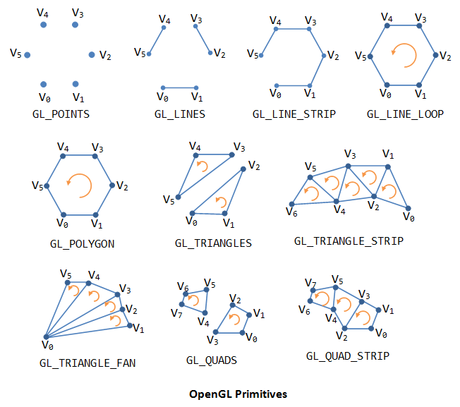
1. OSG绘制简单线
使用简单线绘制,使用OpenGL的绘制的线的能力过程
		// create Geometry object to store all the vertices and lines primitive.
		osg::Geometry* linesGeom = new osg::Geometry();
		//创建定点数据
		osg::Vec3Array* vertices = new osg::Vec3Array(8);
		(*vertices)[0].set(-1.13704, -2.15188e-09, 0.40373);
		(*vertices)[1].set(-0.856897, -2.15188e-09, 0.531441);
		(*vertices)[2].set(-0.889855, -2.15188e-09, 0.444927);
		(*vertices)[3].set(-0.568518, -2.15188e-09, 0.40373);
		(*vertices)[4].set(-1.00933, -2.15188e-09, 0.370773);
		(*vertices)[5].set(-0.716827, -2.15188e-09, 0.292498);
		(*vertices)[6].set(-1.07936, 9.18133e-09, 0.317217);
		(*vertices)[7].set(-0.700348, 9.18133e-09, 0.362533);


		// 设置到定点数组
		linesGeom->setVertexArray(vertices);

		// set the colors as before, plus using the above
		osg::Vec4Array* colors = new osg::Vec4Array;
		colors->push_back(osg::Vec4(1.0f, 1.0f, 0.0f, 1.0f));
		linesGeom->setColorArray(colors, osg::Array::BIND_OVERALL);

		//设置线宽
		osg::LineWidth* linew = new osg::LineWidth(4);
		linesGeom->getOrCreateStateSet()->setAttributeAndModes(linew);

		// 对应上图绘制线的参数
		linesGeom->addPrimitiveSet(new osg::DrawArrays(osg::PrimitiveSet::LINE_LOOP, 0, 8));

		// add the points geometry to the geode.
		geode->addDrawable(linesGeom);
2. osg 绘制简单面
		osg::Geometry* linesGeom = new osg::Geometry();
		//创建定点数据
		osg::Vec3Array* vertices = new osg::Vec3Array(8);
		(*vertices)[0].set(-1.13704, -2.15188e-09, 0.40373);
		(*vertices)[1].set(-0.856897, -2.15188e-09, 0.531441);
		(*vertices)[2].set(-0.889855, -2.15188e-09, 0.444927);
		(*vertices)[3].set(-0.568518, -2.15188e-09, 0.40373);
		(*vertices)[4].set(-1.00933, -2.15188e-09, 0.370773);
		(*vertices)[5].set(-0.716827, -2.15188e-09, 0.292498);
		(*vertices)[6].set(-1.07936, 9.18133e-09, 0.317217);
		(*vertices)[7].set(-0.700348, 9.18133e-09, 0.362533);


		// 设置到定点数组
		linesGeom->setVertexArray(vertices);

		// set the colors as before, plus using the above
		osg::Vec4Array* colors = new osg::Vec4Array;
		colors->push_back(osg::Vec4(1.0f, 0.0f, 0.5f, 0.5f));
		linesGeom->setColorArray(colors, osg::Array::BIND_OVERALL);


		// This time we simply use primitive, and hardwire the number of coords to use
		// since we know up front,
		linesGeom->addPrimitiveSet(new osg::DrawArrays(osg::PrimitiveSet::POLYGON, 0, 8));

		// add the points geometry to the geode.
		geode->addDrawable(linesGeom);
说明不规则多边形绘会出现一些问题,osg中解决两种解决办法
- 自己三角化多边形,网上可以搜索一些算法
- 使用osg::Tessellator
- 关键代码
		osg::ref_ptr<osgUtil::Tessellator> tscx = new osgUtil::Tessellator();
		tscx->setTessellationNormal(osg::Vec3(0.0, -1.0, 0));//面的法线向量
		tscx->setTessellationType(osgUtil::Tessellator::TESS_TYPE_GEOMETRY);
		tscx->setBoundaryOnly(false);
		tscx->setWindingType(osgUtil::Tessellator::TESS_WINDING_ODD); // the commonest tessellation is default, ODD. GE2 allows intersections of constraints to be found.
		tscx->retessellatePolygons(*(linesGeom)); // this should insert extra vertices where constraints overlap
前后对比
| 使用前 | 使用后 |
|---|---|
3. 使用纹理绘制多边形
主要能解决绘制带符号样式的面,不仅仅是简单颜色填充的面。
用到了OpenGL纹理填充的知识
参照
	osg::Geometry* linesGeom = new osg::Geometry();
		//创建定点数据
		osg::Vec3Array* vertices = new osg::Vec3Array(8);
		(*vertices)[0].set(-1.13704, -2.15188e-09, 0.40373);
		(*vertices)[1].set(-0.856897, -2.15188e-09, 0.531441);
		(*vertices)[2].set(-0.889855, -2.15188e-09, 0.444927);
		(*vertices)[3].set(-0.568518, -2.15188e-09, 0.40373);
		(*vertices)[4].set(-1.00933, -2.15188e-09, 0.370773);
		(*vertices)[5].set(-0.716827, -2.15188e-09, 0.292498);
		(*vertices)[6].set(-1.07936, 9.18133e-09, 0.317217);
		(*vertices)[7].set(-0.700348, 9.18133e-09, 0.362533);

		// 设置到定点数组
		linesGeom->setVertexArray(vertices);

		// set the colors as before, plus using the above
		osg::Vec4Array* colors = new osg::Vec4Array;
		colors->push_back(osg::Vec4(1.0f, 0.0f, 0.5f, 0.5f));
		linesGeom->setColorArray(colors, osg::Array::BIND_OVERALL);
		//
		osg::Vec3Array* normals = new osg::Vec3Array;
		normals->push_back(osg::Vec3(0.0f, -1.0f, 0.0f));
		linesGeom->setNormalArray(normals, osg::Array::BIND_OVERALL);
		//设置线宽

		// This time we simply use primitive, and hardwire the number of coords to use
		// since we know up front,
		linesGeom->addPrimitiveSet(new osg::DrawArrays(osg::PrimitiveSet::POLYGON, 0, 8));
		//贴图纹理
		osg::Texture2D* texture = new osg::Texture2D;
		texture->setWrap(osg::Texture2D::WRAP_S, osg::Texture2D::WrapMode::REPEAT);//贴图填充的方式
		texture->setWrap(osg::Texture2D::WRAP_T, osg::Texture2D::WrapMode::REPEAT);//贴图填充的方式
		texture->setDataVariance(osg::Object::DYNAMIC); // protect from being optimized away as static state.
		texture->setImage(osgDB::readRefImageFile("a-duijiangji_select.png"));

		osg::StateSet* stateset = linesGeom->getOrCreateStateSet();
		stateset->setTextureAttributeAndModes(0, texture, osg::StateAttribute::ON);
		//
		stateset->setMode(GL_BLEND, osg::StateAttribute::ON);//开启透明
		stateset->setMode(GL_DEPTH_TEST, osg::StateAttribute::OFF);//关闭深度测试
		osg::BlendFunc * aphlafunc = new osg::BlendFunc(GL_SRC_ALPHA, GL_ONE_MINUS_SRC_ALPHA);
		stateset->setAttribute(aphlafunc, osg::StateAttribute::ON);
		osg::Program* program = new osg::Program;
		program->setName("microshader");
		//shader

		 const char *microshaderVertSource = {
			"// microshader - colors a fragment based on its position\n"
			"varying vec2 m_tex;\n"
			"void main(void)\n"
			"{\n"
			 "    m_tex = vec2(gl_Vertex.x*20.0,gl_Vertex.z*20.0);\n"//面纹理的主要方法
			"    gl_Position = gl_ModelViewProjectionMatrix * gl_Vertex;\n"
			"}\n"
		};

		 const char *microshaderFragSource = {
			"varying vec2 m_tex;\n"
			"uniform sampler2D baseTexture;                                          \n"
			"void main(void)\n"
			"{\n"
			"    gl_FragColor = texture2D( baseTexture, m_tex );\n"
			"}\n"
		};

		program->addShader(new osg::Shader(osg::Shader::VERTEX, microshaderVertSource));
		program->addShader(new osg::Shader(osg::Shader::FRAGMENT, microshaderFragSource));
		stateset->setAttributeAndModes(program, osg::StateAttribute::ON);
		// add the points geometry to the geode.
		geode->addDrawable(linesGeom);
		//
		osg::ref_ptr<osgUtil::Tessellator> tscx = new osgUtil::Tessellator();
		tscx->setTessellationNormal(osg::Vec3(0.0, -1.0, 0));//面的法线向量
		tscx->setTessellationType(osgUtil::Tessellator::TESS_TYPE_GEOMETRY);
		tscx->setBoundaryOnly(false);
		tscx->setWindingType(osgUtil::Tessellator::TESS_WINDING_ODD); // the commonest tessellation is default, ODD. GE2 allows intersections of constraints to be found.
		tscx->retessellatePolygons(*(linesGeom)); // this should insert extra vertices where constraints overlap
绘制效果
4. 实际案例分析
现在有一下需求,在椎体上绘制的,并投影到地面的效果,如下图
分析需要一下技术点:
- osg的OverlayNode的类,
- 椎体的定点和纹理坐标的对应生成
- overlayNode的关键代码
 osgSim::OverlayNode* overlayNode = new osgSim::OverlayNode(technique);
        /*每一帧都更新overlay的纹理*/
        overlayNode->setContinuousUpdate(true);
        /*设置将渲染成纹理的节点*/
        overlayNode->setOverlaySubgraph(movingModel);
        /*设置映射的高度,设成比地面低一点即可*/
        overlayNode->setOverlayBaseHeight(baseHeight-0.01);
        overlayNode->addChild(baseModel);//地面节点
- 椎体以及纹理关键代码
osg::Node* CreateZhuiti(const osg::Vec3& center, float radius, float angle)
{
	float r2 = std::sin(osg::DegreesToRadians(angle))*radius;
	float z = std::cos(osg::DegreesToRadians(angle))*radius;
	int size = 50;
	osg::Vec3Array* vertices = new osg::Vec3Array();
	osg::Vec2Array* coords = new osg::Vec2Array();
	double step = osg::PI * 2 / size;
	for (int i = 0; i < size; i++)
	{
		float x = std::sin(i*step)*r2;
		float y = std::cos(i*step)*r2;
		vertices->push_back(osg::Vec3(x, y, z) + center);
		vertices->push_back(center);
		//纹理坐标
		coords->push_back(osg::Vec2( i*1.0 / size, 1));
		coords->push_back(osg::Vec2( i*1.0 / size, 0));
	}
	vertices->push_back((*vertices)[0]);
	coords->push_back(osg::Vec2(1, 1));
	//
	osg::Geometry* linesGeom = new osg::Geometry();

	// 设置到定点数组
	linesGeom->setVertexArray(vertices);
	linesGeom->setTexCoordArray(0, coords);

	// set the colors as before, plus using the above
	osg::Vec4Array* colors = new osg::Vec4Array;
	colors->push_back(osg::Vec4(1.0f, 1.0f, 1.f, 1.f));
	linesGeom->setColorArray(colors, osg::Array::BIND_OVERALL);
	//
	osg::Texture2D* texture = new osg::Texture2D;
	texture->setDataVariance(osg::Object::DYNAMIC); // protect from being optimized away as static state.
	texture->setImage(osgDB::readRefImageFile("image12.jpg"));

	osg::StateSet* stateset = linesGeom->getOrCreateStateSet();
	stateset->setTextureAttributeAndModes(0, texture, osg::StateAttribute::ON);
	//
	stateset->setMode(GL_BLEND, osg::StateAttribute::ON);//开启透明
														 // since we know up front,
	linesGeom->addPrimitiveSet(new osg::DrawArrays(osg::PrimitiveSet::LINE_STRIP, 0, vertices->size()));

	// add the points geometry to the geode.
	osg::Geode* geode = new osg::Geode;
	geode->addDrawable(linesGeom);
	return geode;
}
最终效果


 被折叠的 条评论
为什么被折叠?
被折叠的 条评论
为什么被折叠?
 到【灌水乐园】发言


