


文章目录
知识框图:
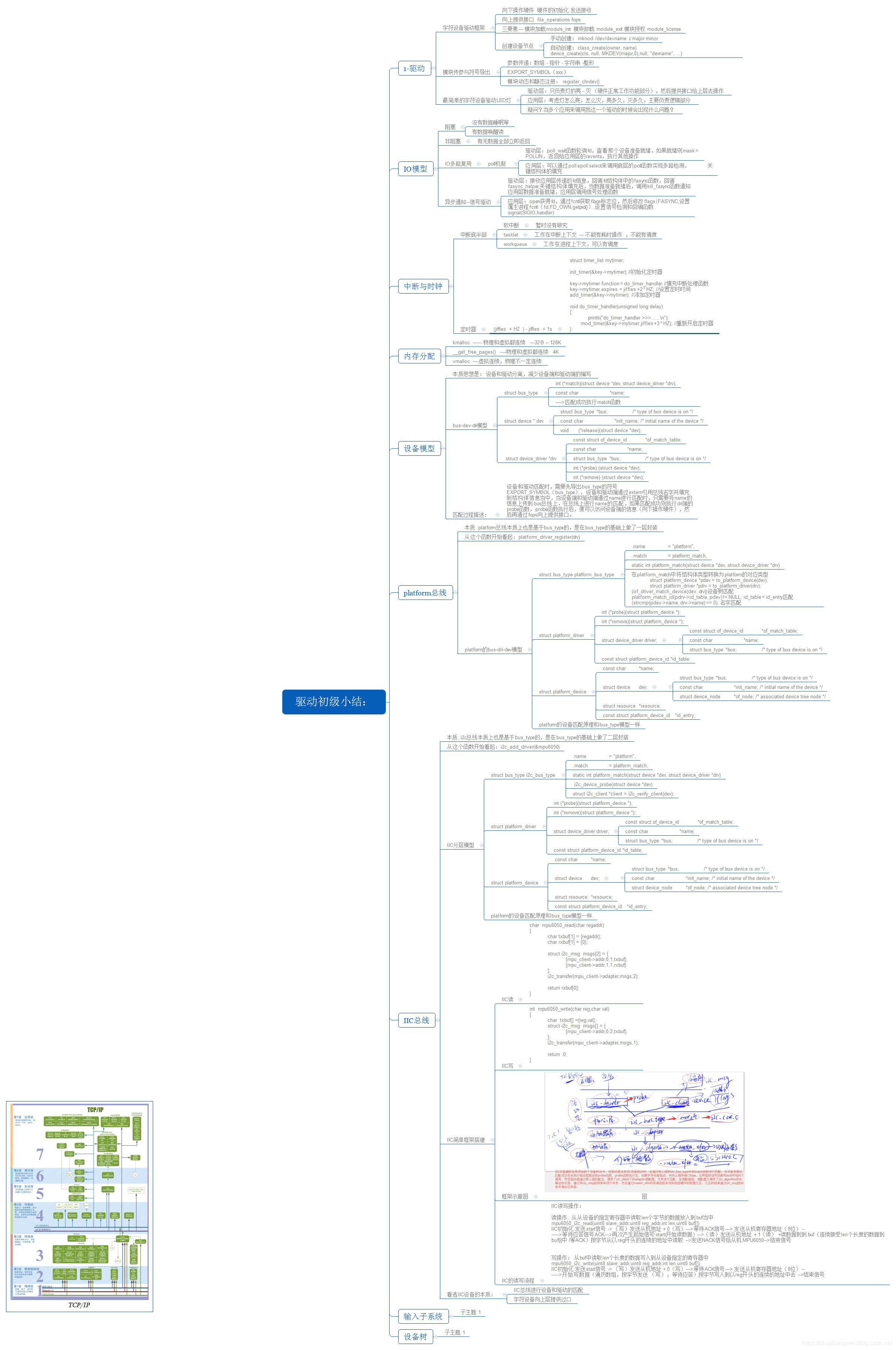
驱动
字符设备驱动框架
-
向下操作硬件
硬件的初始化 发送接收 -
向上提供接口
file_operations fops -
三要素
模块加载module_init
模块卸载 module_exit
模块授权 module_license -
创建设备节点
手动创建:mknod /dev/devname c major minor
自动创建:class_create(owner, name) device_create(cls, null, MKDEV(major,0),null, "devname", ...)
模块传参与符号导出
- 参数传递:数组 - 指针 - 字符串 -整形
- EXPORT_SYMBOL(xxx)
- 模块动态和静态注册: register_chrdev()
最简单的字符设备驱动LED灯
- 驱动层:只负责灯的亮 - 灭 (硬件正常工作功能部分),然后提供接口给上层去操作
- 应用层:考虑灯怎么亮,怎么灭,亮多久,灭多久,主要负责逻辑部分
- 疑问?当多个应用来调用我这一个驱动的时候会出现什么问题?
IO模型
https://blog.csdn.net/Set_Mode/article/details/94356904
阻塞
没有数据睡眠等
有数据唤醒读
非阻塞
有无数据全部立即返回
IO多路复用
poll机制
- 驱动层:poll_wait函数轮询fd,查看那个设备准备就绪,如果就绪则mask = POLLIN,返回给应用层的revents,执行其他操作
- 应用层:可以通过poll epoll select来调用底层的poll函数实现多路检测, 关键结构体的填充
异步通知–信号驱动
- 驱动层:接收应用层传递的fd信息,回调fd结构体中的fasync函数,回调fasync_helper,关键结构体填充后,当数据准备就绪后,调用kill_fasync函数通知应用层数据准备就绪,应用层调用信号处理函数
- 应用层:open获得fd,通过fcntl获取flags标志位,然后修改flags | FASYNC,设置属主进程fcntl(fd,FD_OWN,getpid()),设置信号检测和回调函数 signal(SIGIO,handler)
中断与时钟
中断底半部
- 软中断
暂时没有研究 - tasklet
工作在中断上下文 — 不能有耗时操作 ,不能有调度 - workqueue
工作在进程上下文,可以有调度
定时器
   (jiffies  + HZ  ) - jiffies  = 1s

    struct timer_list mytimer;

    init_timer(&key->mytimer); //初始化定时器

    key->mytimer.function = do_timer_handler; //填充中断处理函数
    key->mytimer.expires  = jiffies +2 * HZ;  //设置定时时间
    add_timer(&key->mytimer);  //添加定时器

    void do_timer_handler(unsigned long delay)
    {
    	printk("do_timer_handler >>>......\n");
    	mod_timer(&key->mytimer,jiffies +3 * HZ);  //重新开启定时器
    }
内存分配
- kmalloc ------ 物理和虚拟都连续 —32B – 128K
- __get_free_pages() ----物理和虚拟都连续 4K
- vmalloc ----虚拟连续,物理不一定连续
设备模型
本质思想
是设备和驱动分离,减少设备端和驱动端的编写
bus-dev-dri模型
| 类型 | 说明 |
|---|---|
| struct bus_type | int (*match)(struct device *dev, struct device_driver *drv) const char *name; ---->匹配成功执行match函数 |
| struct device * dev | truct bus_type bus; / type of bus device is on */ const char init_name; / initial name of the device */ void (*release)(struct device *dev); |
| struct device_driver *drv | const struct of_device_id *of_match_table; const char *name; struct bus_type bus; / type of bus device is on */ int (*probe) (struct device *dev); int (*remove) (struct device *dev); |
匹配过程描述:
设备和驱动匹配时,需要先导出bus_type的符号EXPORT_SYMBOL(bus_type),设备和驱动端通过extern引用总线名字并填充到结构体信息当中,当设备端和驱动端通过name进行匹配时,只需要将name的信息上传到bus总线上,在总线上进行name的匹配,如果匹配成功则执行dri端的probe函数,probe函数执行后,便可以访问设备端的信息(向下操作硬件),然后再通过fops向上提供接口。
platform总线
- 本质 :platform总线本质上也是基于bus_type的,是在bus_type的基础上做了一层封装
- 从这个函数开始看起:platform_driver_register(drv)
- platform的bus-dri-dev模型
| 类型 | 说明 |
|---|---|
| struct bus_type platform_bus_type | .name = “platform”, .match = platform_match, static int platform_match(struct device *dev, struct device_driver *drv) 在platform_match中将结构体类型转换为platform的对应类型 struct platform_device *pdev = to_platform_device(dev); struct platform_driver *pdrv = to_platform_driver(drv); (of_driver_match_device(dev, drv))设备树匹配 platform_match_id(pdrv->id_table, pdev) != NULL; id_table = id_entry匹配 (strcmp(pdev->name, drv->name) == 0); 名字匹配 |
| struct platform_driver | int (*probe)(struct platform_device *); int (*remove)(struct platform_device *); struct device_driver driver; const struct of_device_id *of_match_table; const char *name; struct bus_type bus; / type of bus device is on */ const struct platform_device_id *id_table; |
| struct platform_device | const char *name; struct device dev; struct bus_type bus;/ type of bus device is on */ const char init_name; / initial name of the device */ struct device_node of_node; / associated device tree node */ struct resource *resource;const struct platform_device_id *id_entry; |
- platform的设备匹配原理和bus_type模型一样
IIC总线
从这个函数开始看起:i2c_add_driver(&mpu6050)
IIC分层模型
| 类型 | 说明 |
|---|---|
| struct bus_type i2c_bus_type | .name = “platform”, .match = platform_match, static int platform_match(struct device *dev, struct device_driver *drv) i2c_device_probe(struct device *dev) struct i2c_client *client = i2c_verify_client(dev); |
| struct platform_driver | int (*probe)(struct platform_device *); int (*remove)(struct platform_device *); struct device_driver driver; const struct of_device_id *of_match_table; const char *name; struct bus_type bus; / type of bus device is on */ const struct platform_device_id *id_table; 本质 :i2c总线本质上也是基于bus_type的,是在bus_type的基础上做了二层封装 |
| struct platform_device | const char *name; struct device dev; struct bus_type bus; / type of bus device is on */ const char init_name; / initial name of the device */ struct device_node of_node; / associated device tree node */ struct resource *resource; const struct platform_device_id *id_entry; |
- platform的设备匹配原理和bus_type模型一样
IIC简单框架搭建
-
IIC读
char mpu6050_read(char regaddr) { char txbuf[1] = {regaddr}; char rxbuf[1] = {0}; struct i2c_msg msgs[2] = { {mpu_client->addr,0,1,txbuf}, {mpu_client->addr,1,1,rxbuf} }; i2c_transfer(mpu_client->adapter,msgs,2); return rxbuf[0]; } -
IIC写
int mpu6050_write(char reg,char val) { char txbuf[] ={reg,val}; struct i2c_msg msgs[] = { {mpu_client->addr,0,2,txbuf}, }; i2c_transfer(mpu_client->adapter,msgs,1); return 0; } -
框架示意图

-
IIC的读写流程
IIC读写操作:
读操作: 从从设备的指定寄存器中读取len个字节的数据放入到buf当中
mpu6050_i2c_read(uint8 slave_addr,uint8 reg_addr,int len,uint8 buf[])
IIC初始化 发送start信号 -> (写)发送从机地址 + 0(写)—>等待ACK信号—> 发送从机寄存器地址(8位)–
----->等待应答信号ACK—>再次产生起始信号start(开始读数据) —>(读)发送从机地址 + 1(读) +读数据到到buf(连续接受len个长度的数据到buf[i]中 /等ACK)按字节从以reg开头的连续的地址中读取 -->发送NACK信号给从机MPU6050–>结束信号写操作: 从buf中读取len个长度的数据写入到从设备指定的寄存器中
mpu6050_i2c_write(uint8 slave_addr,uint8 reg_addr,int len,uint8 buf[])
IIC初始化 发送start信号 -> (写)发送从机地址 + 0(写)—>等待ACK信号—> 发送从机寄存器地址(8位)–
----->开始写数据(遍历数组,按字节发送 (写),等待应答)按字节写入到以reg开头的连续的地址中去 -->结束信号
看透IIC设备的本质:
IIC总线进行设备和驱动的匹配 字符设备向上层提供过口
输入子系统
https://blog.csdn.net/Set_Mode/article/details/93374846
https://blog.csdn.net/Set_Mode/article/details/93748334


 1603
1603

 被折叠的 条评论
为什么被折叠?
被折叠的 条评论
为什么被折叠?
 到【灌水乐园】发言


