


(一)配置有线部分
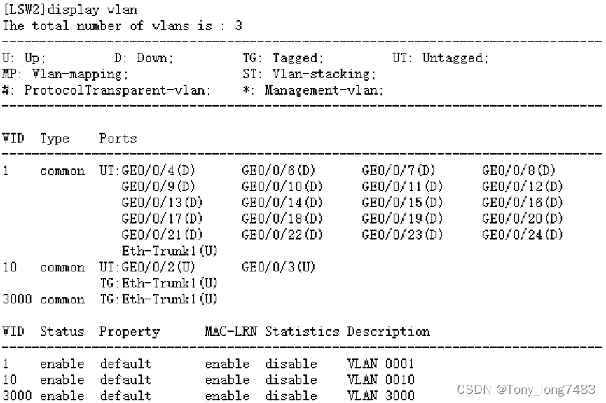
1.配置LSW2
(1)创建相关vlan
[LSW2]vlan batch 10 3000
(2)配置连接LSW1的Eth-Trunk1,透传VLAN 10 3000
[LSW2]int Eth-Trunk 1
[LSW2-Eth-Trunk1]port link-type trunk
[LSW2-Eth-Trunk1]port trunk allow-pass vlan 10 3000
[LSW2-Eth-Trunk1]mode lacp
[LSW2]int g0/0/1
[LSW2-GigabitEthernet0/0/1]eth-trunk 1
[LSW2-GigabitEthernet0/0/1]int g0/0/5
[LSW2-GigabitEthernet0/0/5]eth-trunk 1
(3)配置连接用户的接口,使用户加入VLAN,并将接口配置成边缘端口
[LSW2]int g0/0/2
[LSW2-GigabitEthernet0/0/2]port link-type access
[LSW2-GigabitEthernet0/0/2]port default vlan 10
[LSW2-GigabitEthernet0/0/2]stp edged-port enable
[LSW2-GigabitEthernet0/0/2]int g0/0/3
[LSW2-GigabitEthernet0/0/3]port link-type access
[LSW2-GigabitEthernet0/0/3]port default vlan 10
[LSW2-GigabitEthernet0/0/3]stp edged-port enable
(4)配置BPDU保护功能,加强网络的稳定性
[LSW2]stp bpdu-protection
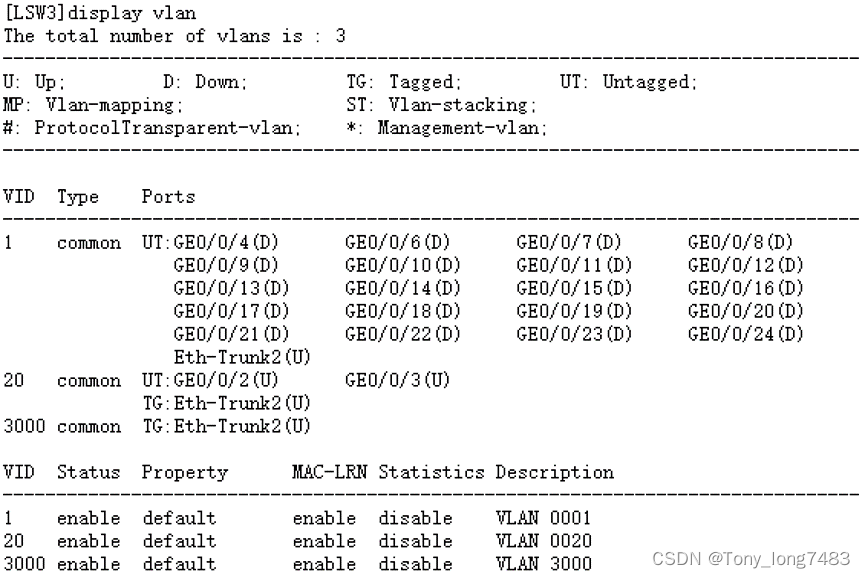
2.配置LSW3,类似LSW2
[LSW3]vlan batch 20 3000
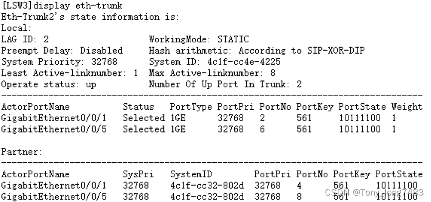
[LSW3]int Eth-Trunk 2
[LSW3-Eth-Trunk2]port link-type trunk
[LSW3-Eth-Trunk2]port trunk allow-pass vlan 20 3000
[LSW3-Eth-Trunk2]mode lacp
[LSW3-Eth-Trunk2]quit
[LSW3]int g0/0/1
[LSW3-GigabitEthernet0/0/1]eth-trunk 2
[LSW3-GigabitEthernet0/0/1]int g0/0/5
[LSW3-GigabitEthernet0/0/5]eth-trunk 2
[LSW3-GigabitEthernet0/0/5]quit
[LSW3]int g0/0/2
[LSW3-GigabitEthernet0/0/2]port link-type access
[LSW3-GigabitEthernet0/0/2]port default vlan 20
[LSW3-GigabitEthernet0/0/2]stp edged-port enable
[LSW3-GigabitEthernet0/0/2]int g0/0/3
[LSW3-GigabitEthernet0/0/3]port link-type access
[LSW3-GigabitEthernet0/0/3]port default vlan 20
[LSW3-GigabitEthernet0/0/3]stp edged-port enable
[LSW3]stp bpdu-protection
3. 配置LSW1
(1)创建相应vlan
[LSW1]vlan batch 10 20 1000 3000
(2)配置与LSW2相连参数
[LSW1]int Eth-Trunk 1
[LSW1-Eth-Trunk1]port link-type trunk
[LSW1-Eth-Trunk1]port trunk allow-pass vlan 10 1000 3000
[LSW1-Eth-Trunk1]mode lacp
[LSW1]int g0/0/2
[LSW1-GigabitEthernet0/0/2]eth-trunk 1
[LSW1-GigabitEthernet0/0/2]int g0/0/6
[LSW1-GigabitEthernet0/0/6]eth-trunk 1
[LSW1]int Vlanif 10
[LSW1-Vlanif10]ip add 192.168.1.1 24
(3)配置与LSW3相连参数
[LSW1]int Eth-Trunk 2
[LSW1-Eth-Trunk2]port link-type trunk
[LSW1-Eth-Trunk2]port trunk allow-pass vlan 20 1000 3000
[LSW1-Eth-Trunk2]mode lacp
[LSW1-Eth-Trunk2]quit
[LSW1]int g0/0/3
[LSW1-GigabitEthernet0/0/3]eth-trunk 2
[LSW1-GigabitEthernet0/0/3]int g0/0/7
[LSW1-GigabitEthernet0/0/7]eth-trunk 2
[LSW1]int Vlanif 20
[LSW1-Vlanif20]ip add 192.168.2.1 24
(4)配置与防火墙相连接口,使园区网络与Internet互通
[LSW1]int g0/0/1
[LSW1-GigabitEthernet0/0/1]port link-type access
[LSW1-GigabitEthernet0/0/1]port default vlan 1000
[LSW1-GigabitEthernet0/0/1]quit
[LSW1]int Vlanif 1000
[LSW1-Vlanif1000]ip add 10.1.1.1 24
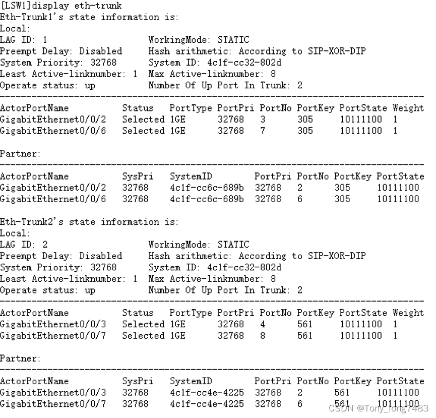
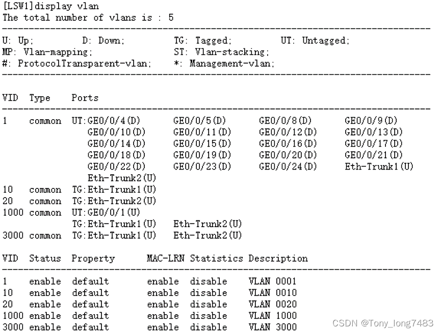
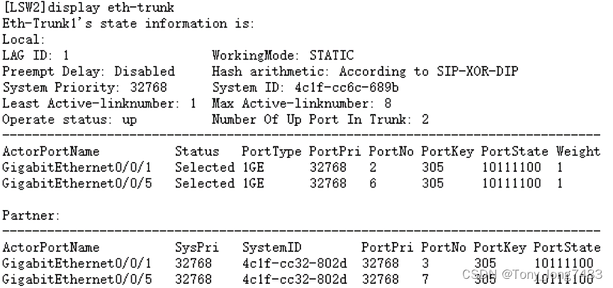
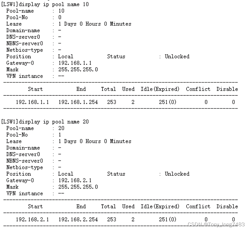
(5)查看配置结果
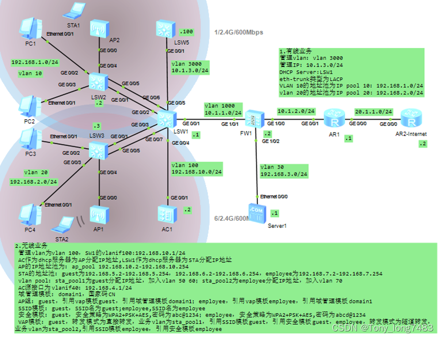
- 配置DHCP:在LSW1上配置DHCP Server,使用户都能获取到正确的IP地址
(1)创建全局地址池,配置出口网关、租期(采用缺省值1天,不需配置)并配置PC3分配固定的IP地址192.168.2.200
[LSW1]dhcp enable
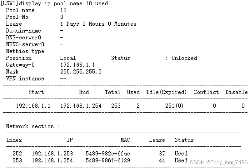
[LSW1]ip pool 10
[LSW1-ip-pool-10]network 192.168.1.0 mask 24
[LSW1-ip-pool-10]gateway-list 192.168.1.1
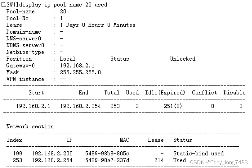
[LSW1-ip-pool-10]ip pool 20
[LSW1-ip-pool-20]network 192.168.2.0 mask 24
[LSW1-ip-pool-20]gateway-list 192.168.2.1
[LSW1-ip-pool-20]static-bind ip-address 192.168.2.200 mac-address 5489-98B8-805C
(2)配置用户从全局地址池获取IP地址
[LSW1]int Vlanif 10
[LSW1-Vlanif10]dhcp select global
[LSW1-Vlanif10]int Vlanif 20
[LSW1-Vlanif20]dhcp select global
(3)查看全局地址池的配置和使用信息
(4)配置完动态分配地址之后,刚开电脑获取地址的时间比较长,这是因为对于开启了生成树协议的交换机,每当有电脑接入之后导致生成树重新收敛,所以需要的时间比较长;通过关闭接口的生成树协议或者把连接终端的交换机接口配置为边缘端口即可解决
[LSW2]int g0/0/2
[LSW2-GigabitEthernet0/0/2]stp edged-port enable
[LSW2-GigabitEthernet0/0/2]int g0/0/3
[LSW2-GigabitEthernet0/0/3]stp edged-port enable
[LSW3]int g0/0/2
[LSW3-GigabitEthernet0/0/2]stp disable
[LSW3-GigabitEthernet0/0/2]int g0/0/3
[LSW3-GigabitEthernet0/0/3]stp disable
5. 配置LSW1路由,使内部网络数据可以发送出去
[LSW1]ip route-static 0.0.0.0 0.0.0.0 10.1.1.2
6. 配置AR1
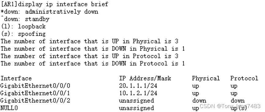
(1)配置IP地址
[AR1]int g0/0/1
[AR1-GigabitEthernet0/0/1]ip add 10.1.2.1 24
[AR1-GigabitEthernet0/0/1]int g0/0/2
[AR1-GigabitEthernet0/0/2]ip add 20.1.1.1 24
(2)配置允许上网的acl,将所有允许访问Internet的用户网段写入该acl
[AR1]acl 2000
[AR1-acl-basic-2000]rule permit source 192.168.1.0 0.0.0.255
[AR1-acl-basic-2000]rule permit source 192.168.2.0 0.0.0.255
[AR1-acl-basic-2000]rule permit source 10.1.1.0 0.0.0.255
[AR1-acl-basic-2000]rule permit source 10.1.2.0 0.0.0.255
(3)在连接Internet的接口配置NAT转换实现内网用户访问Internet
[AR1]int g0/0/0
[AR1-GigabitEthernet0/0/0]nat outbound 2000
(4)配置到内网的明细路由和到公网的静态缺省路由
[AR1]ip route-static 192.168.1.0 24 10.1.2.2
[AR1]ip route-static 192.168.2.0 24 10.1.2.2
[AR1]ip route-static 10.1.1.0 24 10.1.2.2
[AR1]ip route-static 0.0.0.0 0.0.0.0 20.1.1.2
(5)配置DNS地址解析功能,DNS服务器地址为运营商给的
[AR1]dns resolve
[AR1]dns server 8.8.8.8
[AR1]dns proxy enable
7.配置DHCP Snooping和IPSG:配置了DHCP功能之后,用户主机可以自动获取地址。但是为了防止员工在内网私自接一个小路由器并开启DHCP自动分配地址的功能,导致内网合法用户获取到了私接的小路由器分配的地址而不能正常上网,还需要配置DHCP Snooping功能
(1)在LSW2和LSW3上开启DHCP Snooping功能
[LSW2]dhcp enable
[LSW2]dhcp snooping enable
[LSW3]dhcp enable
[LSW3]dhcp snooping enable
(2)在连接DHCP服务器的接口上使能DHCP Snooping功能,并将此接口配置为信任接口
[LSW2]int Eth-Trunk 1
[LSW2-Eth-Trunk1]dhcp snooping enable
[LSW2-Eth-Trunk1]dhcp snooping trusted
[LSW3]int Eth-Trunk 2
[LSW3-Eth-Trunk2]dhcp snooping enable
[LSW3-Eth-Trunk2]dhcp snooping trusted
(3)在连接终端的接口上使能DHCP Snooping功能
[LSW2]int g0/0/2
[LSW2-GigabitEthernet0/0/2]dhcp snooping enable
[LSW2-GigabitEthernet0/0/2]int g0/0/3
[LSW2-GigabitEthernet0/0/3]dhcp snooping enable
[LSW3]int g0/0/2
[LSW3-GigabitEthernet0/0/2]dhcp snooping enable
[LSW3-GigabitEthernet0/0/2]int g0/0/3
[LSW3-GigabitEthernet0/0/3]dhcp snooping enable
(4)在LSW2和LSW3上开启IP报文检查功能:为了防止用户私自更改IP地址后攻击网络,在接入交换机开启DHCP Snooping功能后,还需要开启IP报文检查功能,这样LSW收到报文后会将报文与动态绑定表的表项进行匹配,放行匹配的报文,丢弃不匹配的报文。如果不想对整个VLAN收到的报文进行检查,可以只在连接某个终端的接口上开启IP报文检查功能。
[LSW2]vlan 10
[LSW2-vlan10]ip source check user-bind enable
[LSW3]vlan 20
[LSW3-vlan20]ip source check user-bind enable
8. 配置AR2-Internet
[AR2]int g0/0/0
[AR2-GigabitEthernet0/0/0]ip add 20.1.1.2 24
9.防火墙FW1的配置
(1)配置基本的IP地址
[FW1]int g1/0/1
[FW1-GigabitEthernet1/0/1]ip add 10.1.1.2 24
[FW1-GigabitEthernet1/0/1]int g1/0/0
[FW1-GigabitEthernet1/0/0]ip add 10.1.2.2 24
(2)在接口上开启ping功能后,并将接口加入相关区域,PC可以ping通与防火墙相连的接口
[FW1-GigabitEthernet1/0/0]service-manage enable
[FW1-GigabitEthernet1/0/0]service-manage ping permit
[FW1-GigabitEthernet1/0/0]int g1/0/1
[FW1-GigabitEthernet1/0/1]service-manage enable
[FW1-GigabitEthernet1/0/1]service-manage ping permit
[FW1]firewall zone trust
[FW1-zone-trust]add interface g1/0/1
[FW1-zone-trust]firewall zone untrust
[FW1-zone-untrust]add interface g1/0/0
(3)配置trust和untrust之间的转发策略,使PC3无法访问互联网,其余主机可以访问互联网(配置顺序很重要)
[FW1]security-policy
[FW1-policy-security]rule name deny_internet
[FW1-policy-security-rule-deny_internet]source-zone trust
[FW1-policy-security-rule-deny_internet]source-address 192.168.2.200 32
[FW1-policy-security-rule-deny_internet]destination-zone untrust
[FW1-policy-security-rule-deny_internet]destination-address any
[FW1-policy-security-rule-deny_internet]action deny
[FW1-policy-security]rule name permit_internet
[FW1-policy-security-rule-permit_internet]source-zone trust
[FW1-policy-security-rule-permit_internet]source-address 192.168.1.0 24
[FW1-policy-security-rule-permit_internet]source-address 192.168.2.0 24
[FW1-policy-security-rule-permit_internet]source-address 10.1.1.0 24
[FW1-policy-security-rule-permit_internet]destination-zone untrust
[FW1-policy-security-rule-permit_internet]destination-address any
[FW1-policy-security-rule-permit_internet]action permit
(4)配置防火墙路由
[FW1]ip route-static 192.168.1.0 24 10.1.1.1
[FW1]ip route-static 192.168.2.0 24 10.1.1.1
[FW1]ip route-static 0.0.0.0 0.0.0.0 10.1.2.1
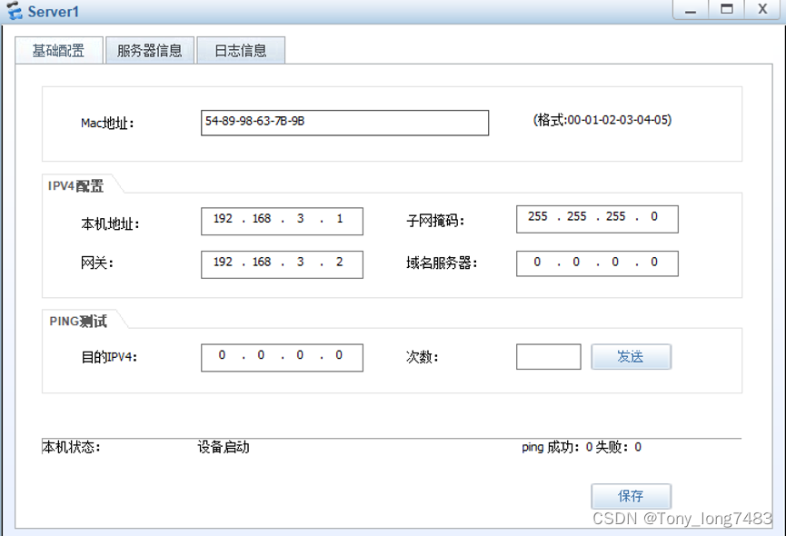
(二)配置服务器
1.配置服务器IP地址
2.配置防火墙IP地址及其区域
[FW1]int g1/0/2
[FW1-GigabitEthernet1/0/2]ip add 192.168.3.2 24
[FW1]firewall zone dmz
[FW1-zone-dmz]add interface g1/0/2
3.配置防火墙策略
(1)配置外网访问DMZ区域
[FW1]security-policy
[FW1-policy-security]rule name untrust_dmz
[FW1-policy-security-rule-untrust_dmz]source-zone untrust
[FW1-policy-security-rule-untrust_dmz]destination-zone dmz
[FW1-policy-security-rule-untrust_dmz]destination-address 192.168.3.0 24
[FW1-policy-security-rule-untrust_dmz]service http
[FW1-policy-security-rule-untrust_dmz]service icmp
[FW1-policy-security-rule-untrust_dmz]action permit
(2)配置内网访问DMZ区域
[FW1-policy-security]rule name trust_dmz
[FW1-policy-security-rule-trust_dmz]source-zone trust
[FW1-policy-security-rule-trust_dmz]source-address 192.168.1.0 24
[FW1-policy-security-rule-trust_dmz]source-address 192.168.2.0 24
[FW1-policy-security-rule-trust_dmz]source-address 10.1.1.0 24
[FW1-policy-security-rule-trust_dmz]destination-zone dmz
[FW1-policy-security-rule-trust_dmz]destination-address 192.168.3.0 24
[FW1-policy-security-rule-trust_dmz]action permit
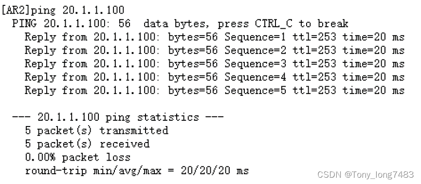
(3)配置NAT Server
[FW1]nat server server1 protocol tcp global 10.1.2.100 www inside 192.168.3.1 www
[FW1]nat server server2 protocol icmp global 10.1.2.100 inside 192.168.3.1 //配置协议icmp,方便用ping测试
[AR1-GigabitEthernet0/0/0]nat server global 20.1.1.100 inside 10.1.2.100
4.配置外网访问server时的路由
[AR1]ip route-static 192.168.3.0 24 10.1.2.2
5.测试
(三)配置无线部分
-
配置网络互通
(1)配置相关vlan
[LSW2]vlan batch 50 60 70 100
[LSW2]int g0/0/4
[LSW2-GigabitEthernet0/0/4]port link-type trunk
[LSW2-GigabitEthernet0/0/4]port trunk allow-pass vlan 50 60 70 100
[LSW2-GigabitEthernet0/0/4]port trunk pvid vlan 100
[LSW2-GigabitEthernet0/0/4]port-isolate enable
[LSW2]int Eth-Trunk 1
[LSW2-Eth-Trunk1]port link-type trunk
[LSW2-Eth-Trunk1]port trunk allow-pass vlan 50 60 70 100
[LSW3]vlan batch 50 60 70 100
[LSW3]int g0/0/4
[LSW3-GigabitEthernet0/0/4]port link-type trunk
[LSW3-GigabitEthernet0/0/4]port trunk allow-pass vlan 50 60 70 100
[LSW3-GigabitEthernet0/0/4]port trunk pvid vlan 100
[LSW3-GigabitEthernet0/0/4]port-isolate enable
[LSW3]int Eth-Trunk 2
[LSW3-Eth-Trunk2]port link-type trunk
[LSW3-Eth-Trunk2]port trunk allow-pass vlan 50 60 70 100
[LSW1]vlan batch 50 60 70 100
[LSW1]int Eth-Trunk 1
[LSW1-Eth-Trunk1]port link-type trunk
[LSW1-Eth-Trunk1]port trunk allow-pass vlan 50 60 70 100
[LSW1]int Eth-Trunk 2
[LSW1-Eth-Trunk2]port link-type trunk
[LSW1-Eth-Trunk2]port trunk allow-pass vlan 50 60 70 100
[LSW1-GigabitEthernet0/0/4]port link-type trunk
[LSW1-GigabitEthernet0/0/4]port trunk allow-pass vlan 70 100
[AC1]vlan batch 50 60 70 100
[AC1]int g0/0/1
[AC1-GigabitEthernet0/0/1]port link-type trunk
[AC1-GigabitEthernet0/0/1]port trunk allow-pass vlan 70 100
(2)配置IP地址
[LSW1]int Vlanif 100
[LSW1-Vlanif100]ip add 192.168.10.1 24
[LSW1-Vlanif100]int Vlanif 50
[LSW1-Vlanif50]ip add 192.168.5.1 24
[LSW1-Vlanif50]int Vlanif 60
[LSW1-Vlanif60]ip add 192.168.6.1 24
[LSW1-Vlanif60]int Vlanif 70
[LSW1-Vlanif70]ip add 192.168.7.1 24
[AC1]int Vlanif 100
[AC1-Vlanif100]ip add 192.168.10.2 24
(3)配置路由
[FW1]ip route-static 192.168.5.0 24 10.1.1.1
[FW1]ip route-static 192.168.6.0 24 10.1.1.1
[FW1]ip route-static 192.168.7.0 24 10.1.1.1
[FW1]ip route-static 192.168.10.0 24 10.1.1.1
[AC1]ip route-static 192.168.5.0 24 192.168.10.1
[AC1]ip route-static 192.168.6.0 24 192.168.10…1
[AC1]ip route-static 192.168.7.0 24 192.168.10.1
(4)配置NAT
[AR1-GigabitEthernet0/0/0]undo nat outbound 2000
[AR1]acl 2000
[AR1-acl-basic-2000]rule permit source 192.168.5.0 0.0.0.255
[AR1-acl-basic-2000]rule permit source 192.168.6.0 0.0.0.255
[AR1-acl-basic-2000]rule permit source 192.168.7.0 0.0.0.255
[AR1-acl-basic-2000]rule permit source 192.168.10.0 0.0.0.255
[AR1]int g0/0/0
[AR1-GigabitEthernet0/0/0]nat outbound 2000
(5)配置防火墙策略
[FW1-policy-security]rule name permit_internet
[FW1-policy-security-rule-permit_internet]source-address 192.168.5.0 mask 255.255.255.0
[FW1-policy-security-rule-permit_internet]source-address 192.168.6.0 mask 255.255.255.0
[FW1-policy-security-rule-permit_internet]source-address 192.168.7.0 mask 255.255.255.0
[FW1-policy-security-rule-permit_internet]source-address 192.168.10.0 mask 255.255.255.0
[FW1-policy-security]rule name trust_dmz
[FW1-policy-security-rule-trust_dmz]source-address 192.168.5.0 mask 255.255.255.0
[FW1-policy-security-rule-trust_dmz]source-address 192.168.6.0 mask 255.255.255.0
[FW1-policy-security-rule-trust_dmz]source-address 192.168.7.0 mask 255.255.255.0
[FW1-policy-security-rule-trust_dmz]source-address 192.168.10.0 mask 255.255.255.0 -
配置DHCP服务,为AP和STA分配IP地址
(1)配置AC为AP分配IP地址
[AC1]dhcp enable
[AC1]ip pool ap_pool
[AC1-ip-pool-ap_pool]network 192.168.10.0 mask 24
[AC1-ip-pool-ap_pool]gateway-list 192.168.10.1
[LSW1]dhcp enable
[LSW1]int Vlanif 100
[LSW1-Vlanif100]dhcp select relay
[LSW1-Vlanif100]dhcp relay server-ip 192.168.10.2
(2)配置SW1作为DHCP服务器为STA分配IP地址
[LSW1]ip pool guest1
[LSW1-ip-pool-guest1]network 192.168.5.0 mask 24
[LSW1-ip-pool-guest1]gateway-list 192.168.5.1
[LSW1]ip pool guest2
[LSW1-ip-pool-guest2]network 192.168.6.0 mask 24
[LSW1-ip-pool-guest2]gateway-list 192.168.6.1
[LSW1]ip pool employee
[LSW1-ip-pool-employee]network 192.168.7.0 mask 24
[LSW1-ip-pool-employee] gateway-list 192.168.7.1
[LSW1]int Vlanif 50
[LSW1-Vlanif50]dhcp select global
[LSW1-Vlanif50]int Vlanif 60
[LSW1-Vlanif60]dhcp select global
[LSW1-Vlanif60]int Vlanif 70
[LSW1-Vlanif70]dhcp select global
(3)配置VLAN pool,用于作为业务VLAN
[AC1]vlan pool sta_pool1
[AC1-vlan-pool-sta_pool1]vlan 50 60
[AC1-vlan-pool-sta_pool1]assignment hash
[AC1]vlan pool sta_pool2
[AC1-vlan-pool-sta_pool2]vlan 70
[AC1-vlan-pool-sta_pool2]assignment hash -
配置AP上线
(1)创建AP组
[AC1]wlan
[AC1-wlan-view]ap-group name guest
[AC1-wlan-ap-group-guest]quit
[AC1-wlan-view]ap-group name employee
(2)创建域管理模板
[AC1-wlan-view]regulatory-domain-profile name domain1
[AC1-wlan-regulate-domain-domain1]country-code cn
[AC1-wlan-view]ap-group name guest
[AC1-wlan-ap-group-guest]regulatory-domain-profile domain1
[AC1-wlan-view]ap-group name employee
[AC1-wlan-ap-group-employee]regulatory-domain-profile domain1
(3)配置AC源接口
[AC1]capwap source interface Vlanif 100
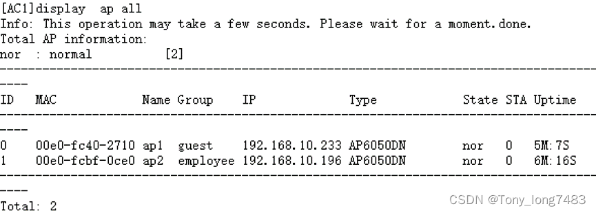
(4)在AC上离线导入AP
[AC1]wlan
[AC1-wlan-view]ap auth-mode mac-auth
[AC1-wlan-view]ap-id 0 ap-mac 00e0-fc40-2710
[AC1-wlan-ap-0]ap-name ap1
[AC1-wlan-ap-0]ap-group guest
[AC1-wlan-view]ap-id 1 ap-mac 00e0-fcbf-0ce0
[AC1-wlan-ap-1]ap-name ap2
[AC1-wlan-ap-1]ap-group employee
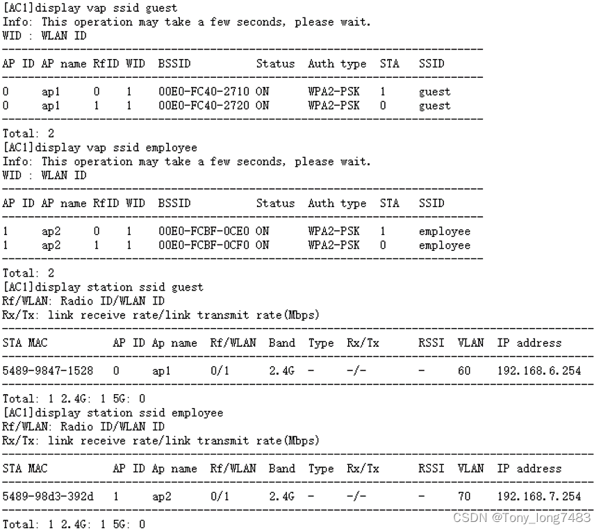
-
配置WLAN业务参数
(1)创建安全模板
[AC1]wlan
[AC1-wlan-view]security-profile name guest
[AC1-wlan-sec-prof-guest]security wpa2 psk pass-phrase abc@1234 aes
[AC1-wlan-view]security-profile name employee
[AC1-wlan-sec-prof-employee]security wpa2 psk pass-phrase abcd@1234 aes
(2)创建SSID模板
[AC1-wlan-view]ssid-profile name guest
[AC1-wlan-ssid-prof-guest]ssid guest
[AC1-wlan-view]ssid-profile name employee
[AC1-wlan-ssid-prof-employee]ssid employee
(3)创建VAP模板
[AC1-wlan-view]vap-profile name guest
[AC1-wlan-vap-prof-guest]forward-mode direct-forward
[AC1-wlan-vap-prof-guest]service-vlan vlan-pool sta_pool1
[AC1-wlan-vap-prof-guest]security-profile guest
[AC1-wlan-vap-prof-guest]ssid-profile guest
[AC1-wlan-view]vap-profile name employee
[AC1-wlan-vap-prof-employee]forward-mode tunnel
[AC1-wlan-vap-prof-employee]service-vlan vlan-pool sta_pool2
[AC1-wlan-vap-prof-employee]security-profile employee
[AC1-wlan-vap-prof-employee]ssid-profile employee
(4)配置AP组引用VAP模板,AP上射频使用VAP模板的配置
[AC1-wlan-view]ap-group name guest
[AC1-wlan-ap-group-guest]vap-profile guest wlan 1 radio 0
[AC1-wlan-ap-group-guest]vap-profile guest wlan 1 radio 1
[AC1-wlan-view]ap-group name employee
[AC1-wlan-ap-group-employee]vap-profile employee wlan 1 radio 0
[AC1-wlan-ap-group-employee]vap-profile employee wlan 1 radio 1 -
配置AP射频的信道和功率
[AC1-wlan-view]ap-id 0
[AC1-wlan-ap-0]radio 0
[AC1-wlan-radio-0/0]channel 20mhz 6
[AC1-wlan-radio-0/0]eirp 127
[AC1-wlan-radio-0/0]radio 1
[AC1-wlan-radio-0/1]channel 20mhz 149
[AC1-wlan-radio-0/1]eirp 127
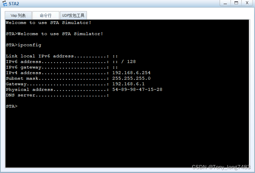
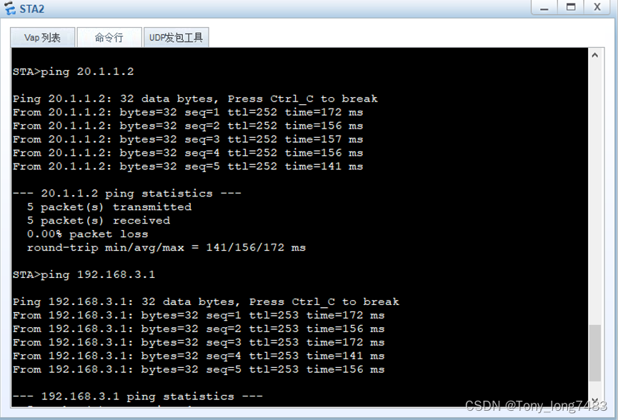
6.验证配置:sta连接AP

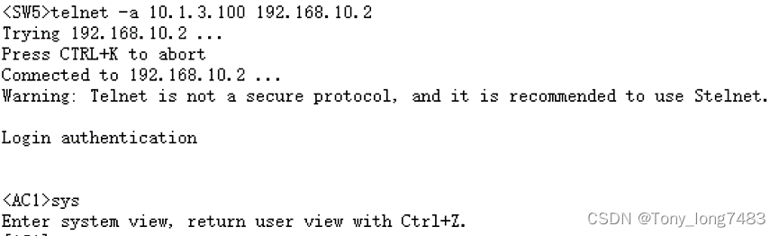
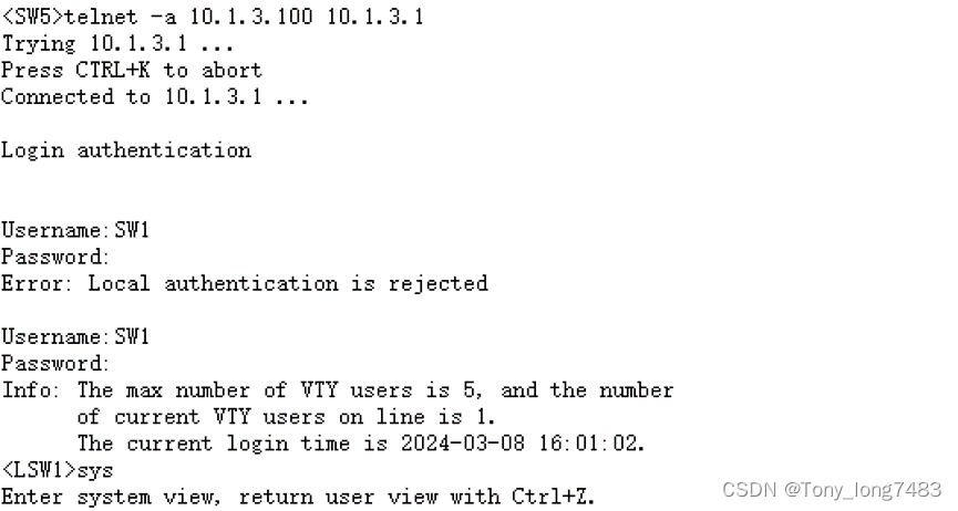
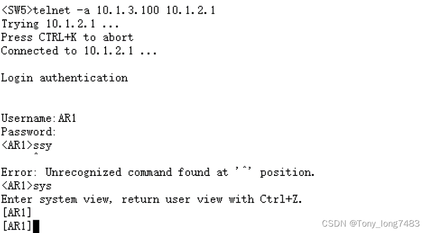
(四)设备Telnet配置:SW5为管理端,用以Telnet其他设备
1.配置相关IP地址
[LSW2]int Vlanif 3000
[LSW2-Vlanif3000]ip add 10.1.3.2 24
[LSW3]int Vlanif 3000
[LSW3-Vlanif3000]ip add 10.1.3.3 24
[LSW1]int g0/0/5
[LSW1-GigabitEthernet0/0/5]port link-type access
[LSW1-GigabitEthernet0/0/5]port default vlan 3000 [LSW1]int Vlanif 3000
[LSW1-Vlanif3000]ip add 10.1.3.1 24
[SW5]int g0/0/1
[SW5-GigabitEthernet0/0/1]port link-type trunk
[SW5-GigabitEthernet0/0/1]port trunk allow-pass vlan 3000
[SW5-GigabitEthernet0/0/1]port trunk pvid vlan 3000
[SW5]vlan 3000
[SW5]int Vlanif 3000
[SW5-Vlanif3000]ip add 10.1.3.100 24
2.配置相关路由
[AC1]ip route-static 10.1.3.0 24 192.168.10.1
[FW1]ip route-static 10.1.3.0 24 10.1.1.1
[AR1]ip route-static 10.1.3.0 24 10.1.2.2
[SW5]ip route-static 0.0.0.0 0.0.0.0 10.1.3.1
3.配置防火墙放行相关流量
[FW1]security-policy
[FW1-policy-security]rule name telnet_AR1
[FW1-policy-security-rule-telnet_AR1]source-zone trust
[FW1-policy-security-rule-telnet_AR1]source-address 10.1.3.100 0.0.0.0
[FW1-policy-security-rule-telnet_AR1]destination-zone untrust
[FW1-policy-security-rule-telnet_AR1]destination-address 10.1.2.0 0.0.0.255
[FW1-policy-security-rule-telnet_AR1]source-zone untrust
[FW1-policy-security-rule-telnet_AR1]source-address 10.1.2.0 24
[FW1-policy-security-rule-telnet_AR1]destination-zone trust
[FW1-policy-security-rule-telnet_AR1]destination-address 10.1.3.100 32
[FW1-policy-security-rule-telnet_AR1]service telnet
[FW1-policy-security-rule-telnet_AR1]action permit
[FW1-policy-security]rule name telnet_FW1
[FW1-policy-security-rule-telnet_FW1]source-zone trust
[FW1-policy-security-rule-telnet_FW1]source-address 10.1.3.100 0.0.0.0
[FW1-policy-security-rule-telnet_FW1]destination-zone local
[FW1-policy-security-rule-telnet_FW1]source-zone local
[FW1-policy-security-rule-telnet_FW1]destination-zone trust
[FW1-policy-security-rule-telnet_FW1]destination-address 10.1.3.100 32
[FW1-policy-security-rule-telnet_FW1]service telnet
[FW1-policy-security-rule-telnet_FW1]action permit
[FW1-policy-security]rule name telnet_dmz
[FW1-policy-security-rule-telnet_dmz]source-zone trust
[FW1-policy-security-rule-telnet_dmz]source-address 10.1.3.100 0.0.0.0
[FW1-policy-security-rule-telnet_dmz]destination-zone dmz
[FW1-policy-security-rule-telnet_dmz]source-zone dmz
[FW1-policy-security-rule-telnet_dmz]destination-zone trust
[FW1-policy-security-rule-telnet_dmz]destination-address 10.1.3.100 32
[FW1-policy-security-rule-telnet_dmz]service telnet
[FW1-policy-security-rule-telnet_dmz]action permit
4.创建相关账号
[AC1]telnet server enable
[AC1]aaa
[AC1-aaa]local-user ac1 password irreversible-cipher abc@1234
[AC1-aaa]local-user ac1 privilege level 3
[AC1-aaa]local-user ac1 service-type telnet
[AC1]user-interface vty 0 4
[AC1-ui-vty0-4]authentication-mode aaa
[AC1-ui-vty0-4]user privilege level 3
[LSW1]aaa
[LSW1-aaa]local-user SW1 password cipher abc@1234
[LSW1-aaa]local-user SW1 service-type telnet
[LSW1-aaa]local-user SW1 privilege level 3
[LSW1-ui-vty4]user-interface vty 0 4
[LSW1-ui-vty0-4]authentication-mode aaa
[LSW1-ui-vty0-4]user privilege level 3
[FW1]telnet server enable
[FW1]int g1/0/1
[FW1-GigabitEthernet1/0/1]service-manage enable
[FW1-GigabitEthernet1/0/1]service-manage telnet permit
[FW1]aaa
[FW1-aaa]manager-user FW1
[FW1-aaa-manager-user-FW1]password cipher abc@1234
[FW1-aaa-manager-user-FW1]service-type telnet
[FW1-aaa-manager-user-FW1]level 3
[FW1]user-interface vty 0 4
[FW1-ui-vty0-4]authentication-mode aaa
[FW1-ui-vty0-4]protocol inbound telnet
[FW1-ui-vty0-4]user privilege level 3
[AR1]aaa
[AR1-aaa]local-user AR1 password cipher abc@1234 privilege level 3
[AR1-aaa]local-user AR1 service-type telnet
[AR1]user-interface vty 0 4
[AR1-ui-vty0-4]authentication-mode aaa
[AR1-ui-vty0-4]user privilege level 3
[AR1-ui-vty0-4]authentication-mode aaa
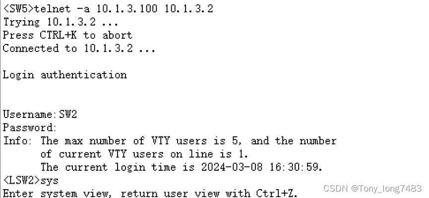
[LSW2]telnet server enable
[LSW2]aaa
[LSW2-aaa]local-user SW2 password cipher abc@1234 privilege level 3
[LSW2-aaa]local-user SW2 service-type telnet
[LSW2]user-interface vty 0 4
[LSW2-ui-vty0-4]authentication-mode aaa
[LSW2-ui-vty0-4]user privilege level 3
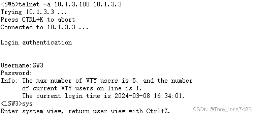
[LSW3]telnet server enable
[LSW3]aaa
[LSW3-aaa]local-user SW3 password cipher abc@1234 privilege level 3
[LSW3-aaa]local-user SW3 service-type telnet
[LSW3]user-interface vty 0 4
[LSW3-ui-vty0-4]authentication-mode aaa
[LSW3-ui-vty0-4]u
[LSW3-ui-vty0-4]user privilege level 3
5.测试


 9321
9321


 被折叠的 条评论
为什么被折叠?
被折叠的 条评论
为什么被折叠?
 到【灌水乐园】发言


