


(The article is a note about BLE connecting in Bluetooth Core spec V4.2)
BLE Connecting
LE Generic Packet Structure (Vol 1 Part A Section 3.2.2)
The general structure of the link layer air interface packet closely reflects the architectural layers found in the LE system. The LE packet structure is designed for optimal use in normal operation. It is shown in Figure 3.5.
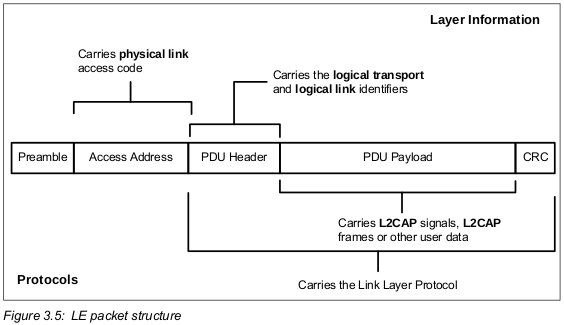
The preamble is octet and the Access Address is 4 octets. The PDU range is from 2 to 257 octets. The CRC is 3 octets.
All LE packets include the Access Address. This is used to identify communications on a physical link, and to exclude or ignore packets on different physical links that are using the same PHY channels in physical proximity. The Access Address determines whether the packet is directed to the advertising physical link or the an active physical link to a device. All LE advertising physical links use a fixed Access Address. LE active physical links use a randomly generated 32-bit value as their Access Address. This provides an high number of active devices that can be addressed in an LE piconet.
For advertising channel PDUs, the PDU header contains the type of advertisement payload, the device address type for addresses contained in the advertisement and advertising channel PDU payload length. Most advertising channel PDU payloads contain the advertiser’s address and advertising data. One advertising channel PDU payload only contains the advertiser’s device address and the initiator’s device address in which the advertisement is directed. Advertising channel PDUs with scan requests payloads contain the scanner’s device address and the advertiser’s device address. Advertising channel PDUs with scan responses contain advertiser’s device address and the scan response data. Advertising channel PDUs with connection request payloads contain the initiator’s device address, advertiser’s device address and connection setup parameters.
Access Address (Vol 6 Part B Section 2.1.2)
To mitigate the unwanted effects of the collision, each transmission on a physical channels starts with an Access Address that is used as a correlation code by devices tuned to the physical channel. This Access Address is a property of the physical channel. The Access Address is present at the start of every transmitted packet.
The Link Layer used one physical channel at a given time.
Whenever the Link Layer is synchronized to the timing, frequency and Access Address of a physical channel it is said to be ‘connected’ to this channel (whether or not it is actively involved in communications over the channel).
The Access Address for all advertising channel packets shall be 1000 1110 1000 1001 1011 1110 1101 0110b (0x8E89BED6).
The Access Address in data channel packets shall be different for each Link Layer connection between any two devices with certain restrictions as defined below. The Access Address shall be a random 32-bit value, generated by the device in the Initiating State and sent in a connection request as defined in Section 2.3.3.1. The initiator shall ensure that the Access Address meets the requirements.
Initiating PDUs (Vol 6 Part B Section 2.3.3)
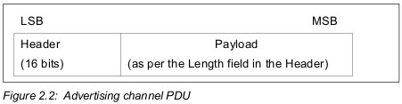
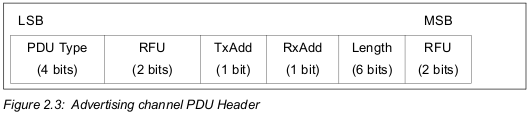
The advertising channel PDU has a 16-bit header and a variable size payload. Its format is as shown in Figure 2.2. The 16 bit Header field of the advertising channel PDU is as shown in Figure 2.3.
CONNECT_REQ advertising channel PDU Type is called the initiating PDU which is sent by the Link Layer in the Initiating State and received by the Link Layer in the Advertising State.
The CONNECT_REQ PDU has the Payload as shown in Figure 2.10. TxAdd in the advertising channel PDU header indicates whether the initiator’s device address in the InitA field is public (TxAdd = 0) or random (TxAdd = 1). The RxAdd in the advertising channel PDU header indicates whether the advertiser’s device address in the AdvA field is public (RxAdd = 0) or random (RxAdd = 1).
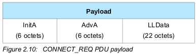
The Payload field consists of InitA, AdvA and LLData fields. The InitA field shall contain the Initiator’s public or random device address as indicated by TxAdd. The AdvA field shall contain the advertiser’s public or random device address as indicated by RxAdd.
The format of the LLData field is shown in Figure 2.11.
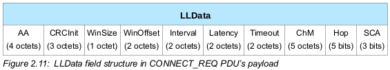
The LLData consists of 10 fields:
- The AA field shall contain the Link Layer connection’s Access Address determined by the Link Layer following the rules specified in Section 2.1.2.
- …
LE Physical Channels (Vol 1 Part A Section 3.3)
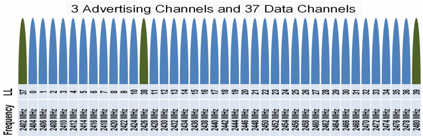
The lowest architectural layer in the Bluetooth system is the physical channel. Two LE physical channels are defined.
The LE piconet channel is used for communication between connected devices and is associated with a specific piconet. There are 37 LE piconet channels.
The LE advertisement broadcast channel is used for broadcasting advertisements to LE devices. These advertisements can be used to discover, connect or send user data to scanner or initiator devices. The LE advertisement broadcast channel is a set of 3 fixed PHY channels spread evenly across the LE frequency spectrum.
In LE the access address, hop index, and channel map are used to identify a physical channel.
LE Physical Links (Vol 1 Part A Section 3.4)
A physical link represents a baseband connection between Bluetooth devices. A physical link is always associated with exactly one physical channel (although a physical channel may support more than one physical link). Within the Bluetooth system a physical link is a virtual concept that has no direct representation within the structure of a transmitted packet.
The LE piconet physical channels support an LE active physical link. The physical link is point-to-point link between the master and slave. It’s always present when the slave is in a connection with the master.
The LE advertising physical channels support an LE advertising physical link. The physical link is a broadcast between the advertiser device and one or more scanner or initiator devices. It is always present when the advertiser is broadcasting advertisement events.
For LE, there is no subsequent part of the packet that directly identifies the physical link. Instead the physical link may be identified by association with the logical transport, as each logical transport is only received on one physical link.
LE Logical Transport (Vol 1 Part A Section 3.5)
Logical Transport has a number of characteristics, including flow control, acknowledgement/repeat mechanisms, sequence numbering and scheduling behavior. Logical transports are able to carry different types of logical links (depending on the type of the logical transport). In the case of some of the Bluetooth logical links these are multiplexed onto the same logical transport. Logical transports may be carried by active physical links on either the basic or the adapted piconet physical channel.
Logical transport identification and real-time (link control) signaling are carried in the packet header, and for some logical links identification is carried in the payload header.
The LE asynchronous connection (LE ACL) logical transport is used to carry LL and L2CAP control signaling and best effort asynchronous user data. The default LE ACL is automatically created between the master and the slave when a device joins a piconet (connects to the LE piconet physical channel). This default LE ACL is assigned an access channel number by the piconet master. This access address is also used to identify the active physical link when required.
Connecting Procedure (Vol 1 Part A Section 4.2.2.5)
The procedure for forming connections is asymmetrical and requires that one Bluetooth device carries out the advertising procedure while the other Bluetooth device carries out the scanning procedure. The advertising procedure can be targeted, so that only one device will respond to the advertising. The scanning device can also target an advertising device by first discovering that the advertising device is present in a connectable manner, and in the given area, and then scanning only connectable advertising events from that device using the device filter. After receiving connectable advertising events from the targeted advertising device, it can initiate a connection by sending the connection request to the targeted advertising device over the advertising broadcast physical channel.
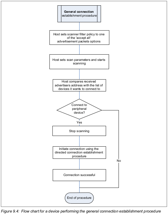
General Connection Establishment Procedure (Vol 3 Part C Section 9.3.6)
The general connection establishment procedure allows the Host to establish a connection with a set of known peer devices in the directed connectable mode or the undirected connectable mode.
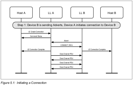
Initiating a connection (Vol 6 Part D Section 5.1)
A device can initiate a connection to an advertiser. This example shows a successful initiation, resulting in both devices able to send application data (see Figure 5.1).
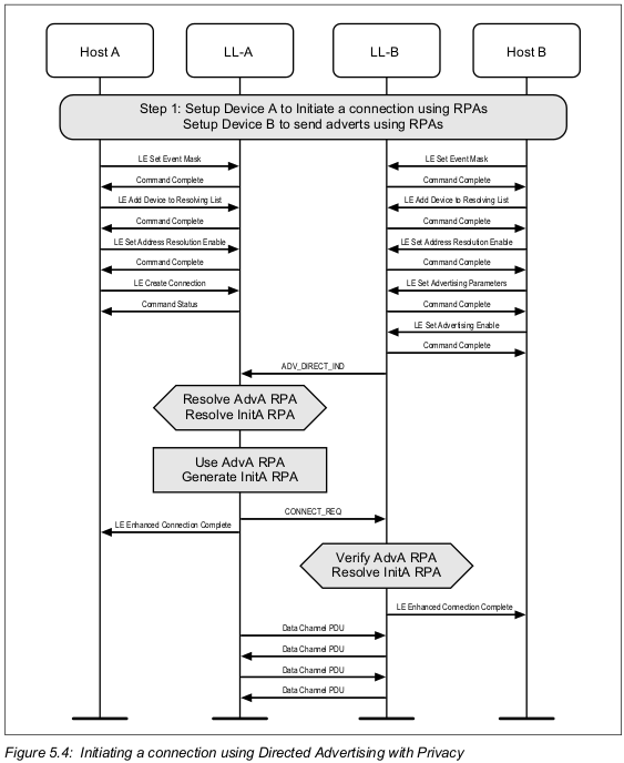
Initiating a Connection using Directed Advertising with Privacy (Vol 6 Part D Section 5.4)
A device can initiate a connection to an advertiser who is using Directed Advertising. Privacy may be used during connection initiation to make it more difficult to track either device during connection setup as well as target a single initiator. The example shows a successful initiation, resulting in both devices able to send application data (see Figure 5.4).
Connection State (Vol 6 Part B Section 4.5)
The Link Layer enters the Connection State when an initiator sends a CONNECT_REQ PDU to an advertiser or an advertiser receives a CONNECT_REQ PDU from an initiator.
After entering the Connection State, the connection is considered to be created. The connection is not considered to be established at this point. A connection is only considered to be established once a data channel packet has been received from the peer device. The only difference between a connection that is created and a connection that is established is the Link Layer connection supervision timeout value that is used (see Section 4.5.2).
When two devices are in a connection, the two devices act in different roles. A Link Layer in the Master Role is called a master. A Link Layer in the Slave Role is called a slave. The master controls the timing of a connection event. A connection event is a point of synchronization between the master and the slave. There shall be only one connection between two LE device addresses. An initiator shall not send a connection request to an advertiser it is already connected to.
If an advertiser receives a connection request from an initiator it is already connected to, it shall ignore that request.
Connected Mode (Vol 1 Part A Section 4.2.2.6)
After a successful connection procedure, the devices are physically connected to each other within a piconet. This means that there is a piconet physical channel to which they are both connected, there is a physical link between the devices, and there are default LE-C and LE-U logical links.
Additional logical links are created using the Link Manager that exchanges LL Protocol messages with the remote Bluetooth device to negotiate the creation and settings for these links.


 823
823

 被折叠的 条评论
为什么被折叠?
被折叠的 条评论
为什么被折叠?
 到【灌水乐园】发言


